Int NISSAN TEANA 2008 Service Manual
[x] Cancel search | Manufacturer: NISSAN, Model Year: 2008, Model line: TEANA, Model: NISSAN TEANA 2008Pages: 5121, PDF Size: 69.03 MB
Page 875 of 5121
BCS-58
< ECU DIAGNOSIS >
BCM (BODY CONTROL MODULE)
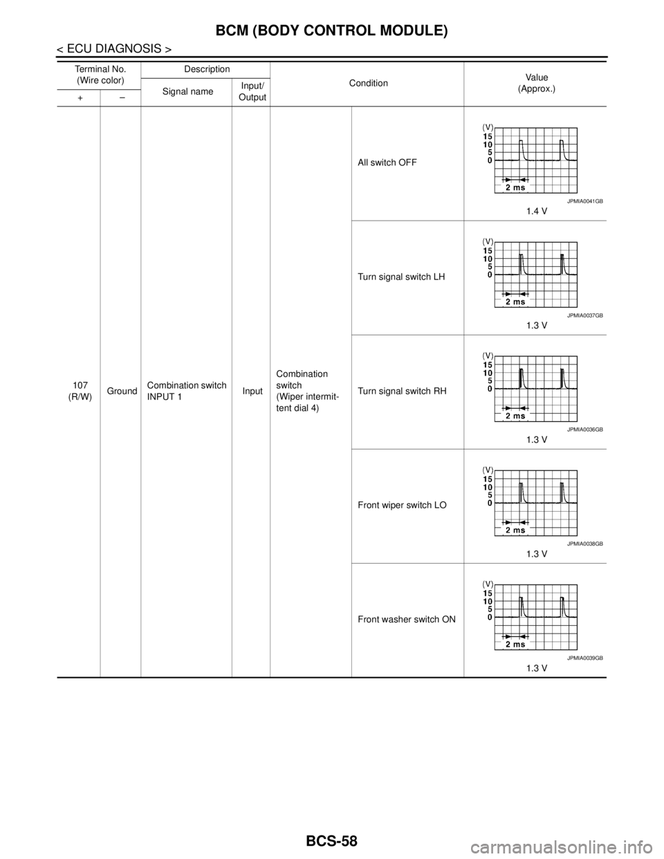
107
(R/W)GroundCombination switch
INPUT 1InputCombination
switch
(Wiper intermit-
tent dial 4)All switch OFF
1.4 V
Turn signal switch LH
1.3 V
Turn signal switch RH
1.3 V
Front wiper switch LO
1.3 V
Front washer switch ON
1.3 V Te r m i n a l N o .
(Wire color)Description
ConditionVa l u e
(Approx.)
Signal nameInput/
Output +–
JPMIA0041GB
JPMIA0037GB
JPMIA0036GB
JPMIA0038GB
JPMIA0039GB
Page 876 of 5121
BCS
BCM (BODY CONTROL MODULE)
BCS-59
< ECU DIAGNOSIS >
C
D
E
F
G
H
I
J
K
L B A
O
P N
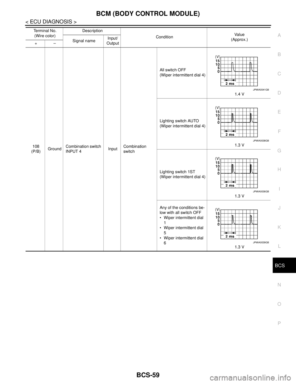
108
(P/B)GroundCombination switch
INPUT 4InputCombination
switchAll switch OFF
(Wiper intermittent dial 4)
1.4 V
Lighting switch AUTO
(Wiper intermittent dial 4)
1.3 V
Lighting switch 1ST
(Wiper intermittent dial 4)
1.3 V
Any of the conditions be-
low with all switch OFF
Wiper intermittent dial
1
Wiper intermittent dial
5
Wiper intermittent dial
6
1.3 V Te r m i n a l N o .
(Wire color)Description
ConditionVa l u e
(Approx.)
Signal nameInput/
Output +–
JPMIA0041GB
JPMIA0038GB
JPMIA0036GB
JPMIA0039GB
Page 877 of 5121
BCS-60
< ECU DIAGNOSIS >
BCM (BODY CONTROL MODULE)
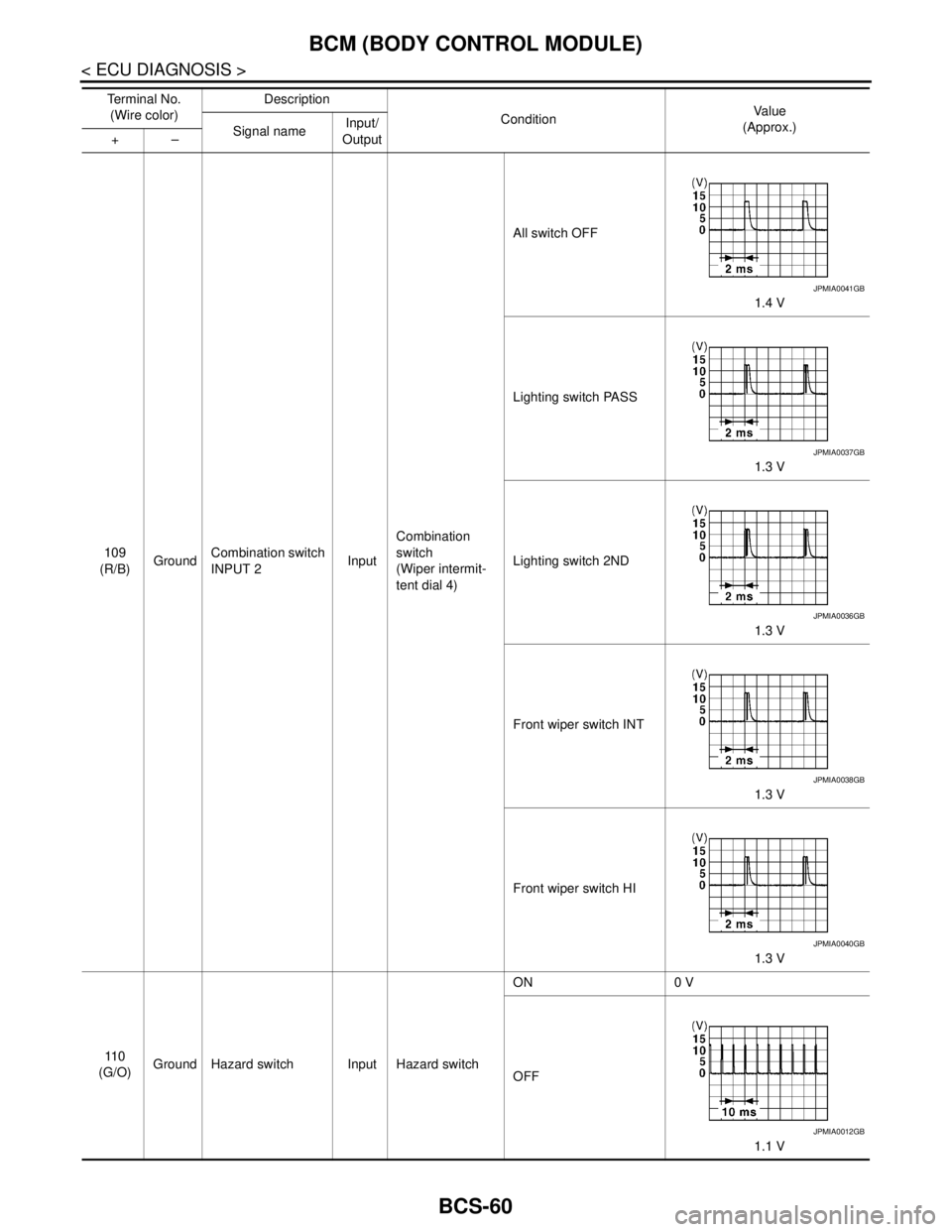
109
(R/B)GroundCombination switch
INPUT 2InputCombination
switch
(Wiper intermit-
tent dial 4)All switch OFF
1.4 V
Lighting switch PASS
1.3 V
Lighting switch 2ND
1.3 V
Front wiper switch INT
1.3 V
Front wiper switch HI
1.3 V
11 0
(G/O)Ground Hazard switch Input Hazard switchON 0 V
OFF
1.1 V Te r m i n a l N o .
(Wire color)Description
ConditionVa l u e
(Approx.)
Signal nameInput/
Output +–
JPMIA0041GB
JPMIA0037GB
JPMIA0036GB
JPMIA0038GB
JPMIA0040GB
JPMIA0012GB
Page 878 of 5121
BCS
BCM (BODY CONTROL MODULE)
BCS-61
< ECU DIAGNOSIS >
C
D
E
F
G
H
I
J
K
L B A
O
P N
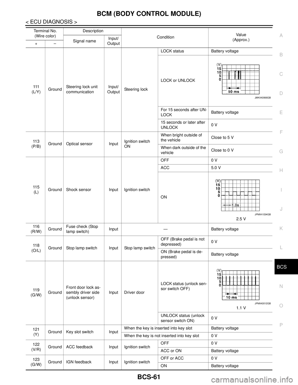
111
(L/Y)GroundSteering lock unit
communicationInput/
OutputSteering lockLOCK status Battery voltage
LOCK or UNLOCK
For 15 seconds after UN-
LOCKBattery voltage
15 seconds or later after
UNLOCK0 V
11 3
(P/B)Ground Optical sensor InputIgnition switch
ONWhen bright outside of
the vehicleClose to 5 V
When dark outside of the
vehicleClose to 0 V
11 5
(L)Ground Shock sensor Input Ignition switchOFF 0 V
ACC 5.0 V
ON
2.5 V
11 6
(R/W)GroundFuse check (Stop
lamp switch)Input — Battery voltage
11 8
(O/L)Ground Stop lamp switch Input Stop lamp switchOFF (Brake pedal is not
depressed)0 V
ON (Brake pedal is de-
pressed)Battery voltage
11 9
(G/W)GroundFront door lock as-
sembly driver side
(unlock sensor)Input Driver doorLOCK status (unlock sen-
sor switch OFF)
1.1 V
UNLOCK status (unlock
sensor switch ON)0 V
121
(Y)Ground Key slot switch InputWhen the key is inserted into key slot Battery voltage
When the key is not inserted into key slot 0 V
122
(V/R)Ground ACC feedback Input Ignition switchOFF 0 V
ACC or ON Battery voltage
123
(G/W)Ground IGN feedback Input Ignition switchOFF or ACC 0 V
ON Battery voltage Te r m i n a l N o .
(Wire color)Description
ConditionVa l u e
(Approx.)
Signal nameInput/
Output +–
JMKIA0066GB
JPMIA1034GB
JPMIA0012GB
Page 880 of 5121
BCS
BCM (BODY CONTROL MODULE)
BCS-63
< ECU DIAGNOSIS >
C
D
E
F
G
H
I
J
K
L B A
O
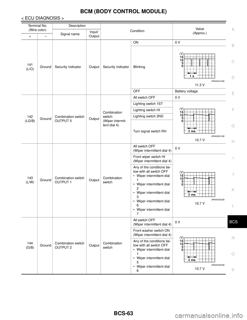
P N141
(L/O)Ground Security indicator Output Security indicatorON 0 V
Blinking
11.3 V
OFF Battery voltage
142
(LG/B)GroundCombination switch
OUTPUT 5OutputCombination
switch
(Wiper intermit-
tent dial 4)All switch OFF 0 V
Lighting switch 1ST
10.7 V Lighting switch HI
Lighting switch 2ND
Turn signal switch RH
143
(L/W)GroundCombination switch
OUTPUT 1OutputCombination
switchAll switch OFF
(Wiper intermittent dial 4)0 V
Front wiper switch HI
(Wiper intermittent dial 4)
10.7 V Any of the conditions be-
low with all switch OFF
Wiper intermittent dial
1
Wiper intermittent dial
2
Wiper intermittent dial
3
Wiper intermittent dial
6
Wiper intermittent dial
7
144
(G/B)GroundCombination switch
OUTPUT 2OutputCombination
switchAll switch OFF
(Wiper intermittent dial 4)0 V
Front washer switch ON
(Wiper intermittent dial 4)
10.7 V Any of the conditions be-
low with all switch OFF
Wiper intermittent dial
1
Wiper intermittent dial
5
Wiper intermittent dial
6 Te r m i n a l N o .
(Wire color)Description
ConditionVa l u e
(Approx.)
Signal nameInput/
Output +–
JPMIA0014GB
JPMIA0031GB
JPMIA0032GB
JPMIA0033GB
Page 881 of 5121
BCS-64
< ECU DIAGNOSIS >
BCM (BODY CONTROL MODULE)
NOTE:
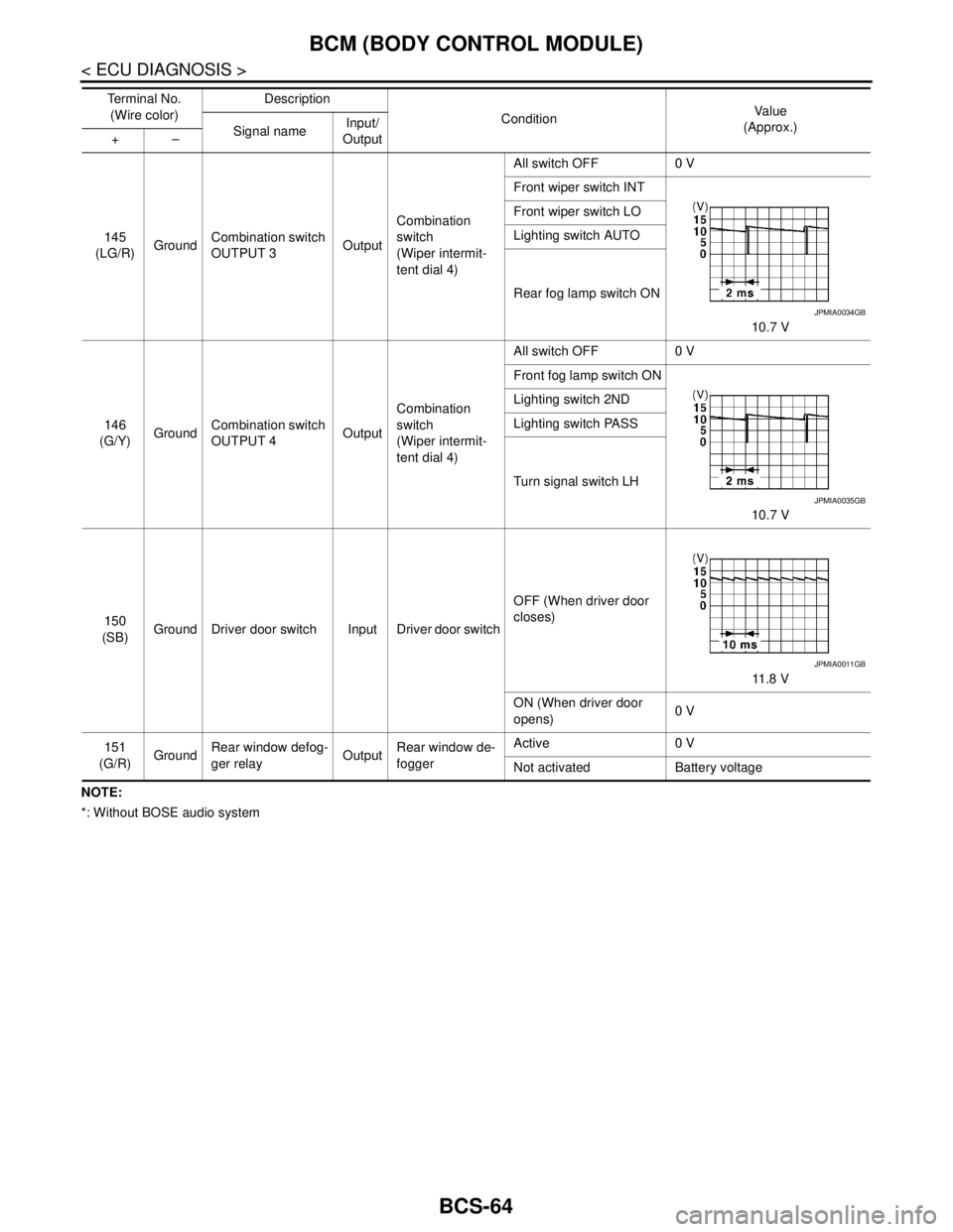
*: Without BOSE audio system145
(LG/R)GroundCombination switch
OUTPUT 3OutputCombination
switch
(Wiper intermit-
tent dial 4)All switch OFF 0 V
Front wiper switch INT
10.7 V Front wiper switch LO
Lighting switch AUTO
Rear fog lamp switch ON
146
(G/Y)GroundCombination switch
OUTPUT 4OutputCombination
switch
(Wiper intermit-
tent dial 4)All switch OFF 0 V
Front fog lamp switch ON
10.7 V Lighting switch 2ND
Lighting switch PASS
Turn signal switch LH
150
(SB)Ground Driver door switch Input Driver door switchOFF (When driver door
closes)
11 . 8 V
ON (When driver door
opens)0 V
151
(G/R)GroundRear window defog-
ger relayOutputRear window de-
foggerActive 0 V
Not activated Battery voltage Te r m i n a l N o .
(Wire color)Description
ConditionVa l u e
(Approx.)
Signal nameInput/
Output +–
JPMIA0034GB
JPMIA0035GB
JPMIA0011GB
Page 889 of 5121
BCS-72
< ECU DIAGNOSIS >
BCM (BODY CONTROL MODULE)
Display contents of CONSULT Fail-safe Cancellation
B2013: ID DISCORD BCM-S/L Inhibit engine cranking Erase DTC
B2014: CHAIN OF S/L-BCM Inhibit engine cranking Erase DTC
B2190: NATS ANTENNA AMP Inhibit engine cranking Erase DTC
B2191: DIFFERENCE OF KEY Inhibit engine cranking Erase DTC
B2192: ID DISCORD BCM-ECM Inhibit engine cranking Erase DTC
B2193: CHAIN OF BCM-ECM Inhibit engine cranking Erase DTC
B2557: VEHICLE SPEED Inhibit steering lockWhen normal vehicle speed signals have been received from ABS
actuator and electric unit (control unit) for 500 ms
B2560: STARTER CONT RELAY Inhibit engine cranking500 ms after the following CAN signal communication status has
become consistent
Starter control relay signal
Starter relay status signal
B2601: SHIFT POSITION Inhibit steering lock500 ms after the following signal reception status becomes consis-
tent
Selector lever P position switch signal
P range signal (CAN)
B2602: SHIFT POSITION Inhibit steering lock5 seconds after the following BCM recognition conditions are ful-
filled
Ignition switch is in the ON position
Selector lever P position switch signal: Except P position (battery
voltage)
Vehicle speed: 4 km/h (2.5 MPH) or more
B2603: SHIFT POSI STATUS Inhibit steering lock500 ms after the following BCM recognition conditions are fulfilled
Ignition switch is in the ON position
Selector lever P position switch signal: Except P position (battery
voltage)
Selector lever P/N position signal: Except P and N positions (0 V)
B2604: PNP SW Inhibit steering lock500 ms after any of the following BCM recognition conditions is ful-
filled
Status 1
- Ignition switch is in the ON position
- Selector lever P/N position signal: P and N position (battery volt-
age)
- P range signal or N range signal (CAN): ON
Status 2
- Ignition switch is in the ON position
- Selector lever P/N position signal: Except P and N positions (0 V)
- P range signal and N range signal (CAN): OFF
B2605: PNP SW Inhibit steering lock500 ms after any of the following BCM recognition conditions is ful-
filled
Ignition switch is in the ON position
- Power position: IGN
- Selector lever P/N position signal: Except P and N positions (0 V)
- Interlock/PNP switch signal (CAN): OFF
Status 2
- Ignition switch is in the ON position
- Selector lever P/N position signal: P or N position (battery volt-
age)
- PNP switch signal (CAN): ON
B2606: S/L RELAY Inhibit engine cranking500 ms after the following CAN signal communication status has
become consistent
Steering lock relay signal (Request signal)
Steering lock relay signal (Condition signal)
B2607: S/L RELAY Inhibit engine cranking500 ms after the following CAN signal communication status has
become consistent
Steering lock relay signal (Request signal)
Steering lock relay signal (Condition signal)
Page 890 of 5121
BCS
BCM (BODY CONTROL MODULE)
BCS-73
< ECU DIAGNOSIS >
C
D
E
F
G
H
I
J
K
L B A
O
P N
HIGH FLASHER OPERATION
BCM detects the turn signal lamp circuit status by the current value.
BCM increases the turn signal lamp blinking speed if the bulb or harness open is detected with the turn signal
lamp operating.
NOTE:
The blinking speed is normal while activating the hazard warning lamp.
DTC Inspection Priority ChartINFOID:0000000003809630
If some DTCs are displayed at the same time, perform inspections one by one based on the following priority
chart.
B2608: STARTER RELAY Inhibit engine cranking500 ms after the following signal communication status becomes
consistent
Starter motor relay control signal
Starter relay status signal (CAN)
B2609: S/L STATUS Inhibit engine cranking
Inhibit steering lockWhen the following steering lock conditions agree
BCM steering lock control status
Steering lock condition No. 1 signal status
Steering lock condition No. 2 signal status
B260A: IGNITION RELAY Inhibit engine cranking500 ms after the following conditions are fulfilled
IGN relay (IPDM E/R) control signal: OFF (Battery voltage)
Ignition ON signal (CAN to IPDM E/R): OFF (Request signal)
Ignition ON signal (CAN from IPDM E/R): OFF (Condition signal)
B260F: ENG STATE SIG LOSTMaintains the power supply
position attained at the time
of DTC detectionWhen any of the following conditions is fulfilled
Power position changes to ACC
Receives engine status signal (CAN)
B2612: S/L STATUS Inhibit engine cranking
Inhibit steering lockWhen any of the following conditions is fulfilled
Steering lock unit status signal (CAN) is received normally
The BCM steering lock control status matches the steering lock
status recognized by the steering lock unit status signal (CAN
from IPDM E/R)
B2617: STARTER RELAY CIRC Inhibit engine cranking1 second after the starter motor relay control inside BCM becomes
normal
B2618: BCM Inhibit engine cranking1 second after the ignition relay (IPDM E/R) control inside BCM be-
comes normal
B2619: BCM Inhibit engine cranking1 second after the steering lock unit power supply output control in-
side BCM becomes normal
B261E: VEHICLE TYPE Inhibit engine cranking BCM initialization
B26E1: ENG STATE NO RES Inhibit engine crankingWhen any of the following conditions is fulfilled
Power position changes to ACC
Receives engine status signal (CAN)
B26E9: S/L STATUS Inhibit engine cranking
Inhibit steering lockWhen BCM transmits the LOCK request signal to steering lock unit,
and receives LOCK response signal from steering lock unit, the fol-
lowing conditions is fulfilled
Steering condition No. 1 signal: LOCK (0 V)
Steering condition No. 2 signal: LOCK (Battery voltage) Display contents of CONSULT Fail-safe Cancellation
Priority DTC
1 B2562: LOW VOLTAGE
2 U1000: CAN COMM CIRCUIT
U1010: CONTROL UNIT (CAN)
3 B2190: NATS ANTENNA AMP
B2191: DIFFERENCE OF KEY
B2192: ID DISCORD BCM-ECM
B2193: CHAIN OF BCM-ECM
Page 891 of 5121
BCS-74
< ECU DIAGNOSIS >
BCM (BODY CONTROL MODULE)
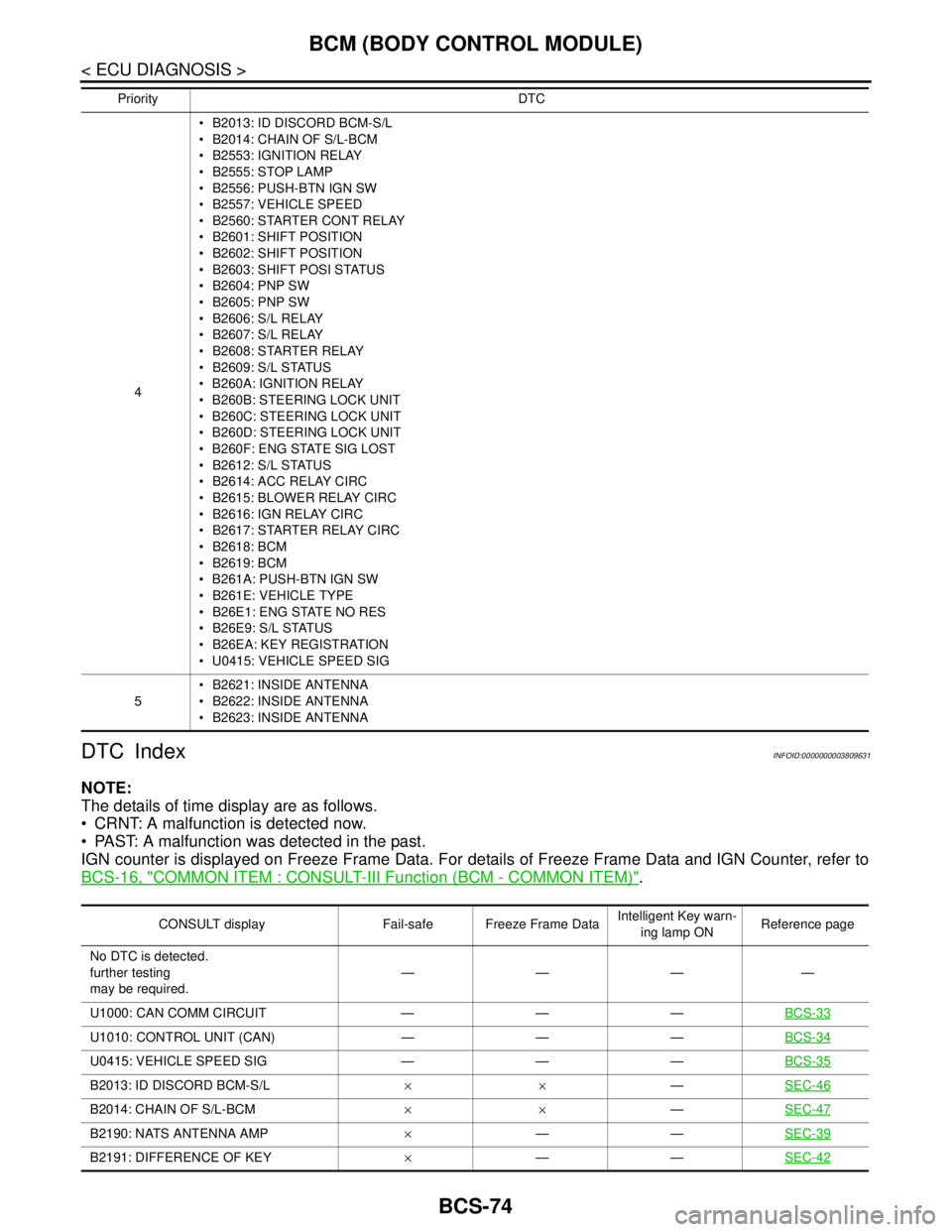
DTC Index
INFOID:0000000003809631
NOTE:
The details of time display are as follows.
CRNT: A malfunction is detected now.
PAST: A malfunction was detected in the past.
IGN counter is displayed on Freeze Frame Data. For details of Freeze Frame Data and IGN Counter, refer to
BCS-16, "
COMMON ITEM : CONSULT-III Function (BCM - COMMON ITEM)".
4 B2013: ID DISCORD BCM-S/L
B2014: CHAIN OF S/L-BCM
B2553: IGNITION RELAY
B2555: STOP LAMP
B2556: PUSH-BTN IGN SW
B2557: VEHICLE SPEED
B2560: STARTER CONT RELAY
B2601: SHIFT POSITION
B2602: SHIFT POSITION
B2603: SHIFT POSI STATUS
B2604: PNP SW
B2605: PNP SW
B2606: S/L RELAY
B2607: S/L RELAY
B2608: STARTER RELAY
B2609: S/L STATUS
B260A: IGNITION RELAY
B260B: STEERING LOCK UNIT
B260C: STEERING LOCK UNIT
B260D: STEERING LOCK UNIT
B260F: ENG STATE SIG LOST
B2612: S/L STATUS
B2614: ACC RELAY CIRC
B2615: BLOWER RELAY CIRC
B2616: IGN RELAY CIRC
B2617: STARTER RELAY CIRC
B2618: BCM
B2619: BCM
B261A: PUSH-BTN IGN SW
B261E: VEHICLE TYPE
B26E1: ENG STATE NO RES
B26E9: S/L STATUS
B26EA: KEY REGISTRATION
U0415: VEHICLE SPEED SIG
5 B2621: INSIDE ANTENNA
B2622: INSIDE ANTENNA
B2623: INSIDE ANTENNA Priority DTC
CONSULT display Fail-safe Freeze Frame DataIntelligent Key warn-
ing lamp ONReference page
No DTC is detected.
further testing
may be required.————
U1000: CAN COMM CIRCUIT — — —BCS-33
U1010: CONTROL UNIT (CAN) — — —BCS-34
U0415: VEHICLE SPEED SIG — — —BCS-35
B2013: ID DISCORD BCM-S/L××—SEC-46
B2014: CHAIN OF S/L-BCM××—SEC-47
B2190: NATS ANTENNA AMP×——SEC-39
B2191: DIFFERENCE OF KEY×——SEC-42
Page 892 of 5121
BCS
BCM (BODY CONTROL MODULE)
BCS-75
< ECU DIAGNOSIS >
C
D
E
F
G
H
I
J
K
L B A
O
P N
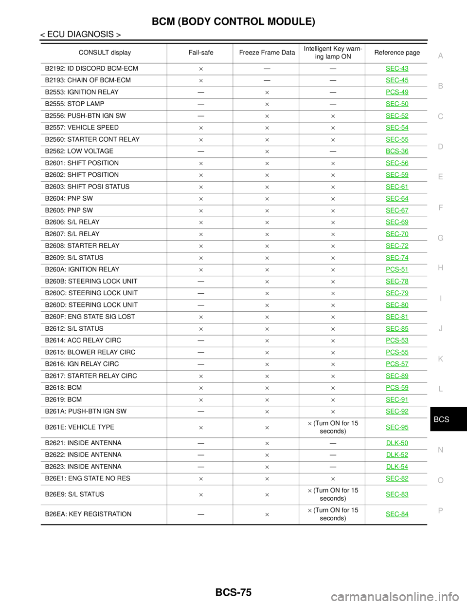
B2192: ID DISCORD BCM-ECM×——SEC-43
B2193: CHAIN OF BCM-ECM×——SEC-45
B2553: IGNITION RELAY —×—PCS-49
B2555: STOP LAMP —×—SEC-50
B2556: PUSH-BTN IGN SW —××SEC-52
B2557: VEHICLE SPEED×××SEC-54
B2560: STARTER CONT RELAY×××SEC-55
B2562: LOW VOLTAGE —×—BCS-36
B2601: SHIFT POSITION×××SEC-56
B2602: SHIFT POSITION×××SEC-59
B2603: SHIFT POSI STATUS×××SEC-61
B2604: PNP SW×××SEC-64
B2605: PNP SW×××SEC-67
B2606: S/L RELAY×××SEC-69
B2607: S/L RELAY×××SEC-70
B2608: STARTER RELAY×××SEC-72
B2609: S/L STATUS×××SEC-74
B260A: IGNITION RELAY×××PCS-51
B260B: STEERING LOCK UNIT —××SEC-78
B260C: STEERING LOCK UNIT —××SEC-79
B260D: STEERING LOCK UNIT —××SEC-80
B260F: ENG STATE SIG LOST×××SEC-81
B2612: S/L STATUS×××SEC-85
B2614: ACC RELAY CIRC —××PCS-53
B2615: BLOWER RELAY CIRC —××PCS-55
B2616: IGN RELAY CIRC —××PCS-57
B2617: STARTER RELAY CIRC×××SEC-89
B2618: BCM×××PCS-59
B2619: BCM×××SEC-91
B261A: PUSH-BTN IGN SW —××SEC-92
B261E: VEHICLE TYPE××× (Turn ON for 15
seconds)SEC-95
B2621: INSIDE ANTENNA —×—DLK-50
B2622: INSIDE ANTENNA —×—DLK-52
B2623: INSIDE ANTENNA —×—DLK-54
B26E1: ENG STATE NO RES×××SEC-82
B26E9: S/L STATUS××× (Turn ON for 15
seconds)SEC-83
B26EA: KEY REGISTRATION —×× (Turn ON for 15
seconds)SEC-84
CONSULT display Fail-safe Freeze Frame DataIntelligent Key warn-
ing lamp ONReference page