Int NISSAN TEANA 2008 Service Manual
[x] Cancel search | Manufacturer: NISSAN, Model Year: 2008, Model line: TEANA, Model: NISSAN TEANA 2008Pages: 5121, PDF Size: 69.03 MB
Page 906 of 5121
BR-10
< ON-VEHICLE MAINTENANCE >
BRAKE FLUID
2. Loosen the bleeder valve, slowly depress the brake pedal to the full stroke, and then release the pedal.
Repeat this operation at intervals of 2 or 3 seconds until all brake fluid is discharged. Then close the
bleeder valve with the brake pedal depressed. Repeat the same work on each wheel.
3. Perform the air bleeding. Refer to BR-10, "
Bleeding Brake System".
Bleeding Brake SystemINFOID:0000000003811176
CAUTION:
Turn the ignition switch OFF and disconnect the ABS actuator and electric unit (control unit) con-
nector or the battery negative terminal before performing the work.
Monitor the fluid level in the sub tank during the air bleeding.
Always use new brake fluid for refilling. Never reuse the drained brake fluid.
1. Connect a vinyl tube to the bleeder valve of the rear right brake.
2. Fully depress the brake pedal 4 to 5 times.
3. Loosen the bleeder valve and bleed air with the brake pedal depressed, and then quickly tighten the
bleeder valve.
4. Repeat steps 2 and 3 until all of the air is out of the brake line.
5. Tighten the bleeder valve to the specified torque.
Front disc brake: refer to BR-34, "
BRAKE CALIPER ASSEMBLY : Exploded View".
Rear disc brake: refer to BR-40, "
BRAKE CALIPER ASSEMBLY : Exploded View".
6. Perform steps 1 to 5 for the rear right brake → front left brake → rear left brake → and front right brake in
order.
7. Check that the fluid level in the sub tank is within the specified range after air bleeding. Refer to BR-9,
"Inspection".
Page 907 of 5121
BRAKE MASTER CYLINDER
BR-11
< ON-VEHICLE MAINTENANCE >
C
D
E
G
H
I
J
K
L
MA
B
BR
N
O
P
BRAKE MASTER CYLINDER
InspectionINFOID:0000000003811177
FLUID LEAK
Check for brake fluid leakage from the master cylinder mounting face, reservoir tank mounting face, and brake
tube connections.
Page 908 of 5121

BR-12
< ON-VEHICLE MAINTENANCE >
BRAKE BOOSTER
BRAKE BOOSTER
InspectionINFOID:0000000003811178
OPERATION
Depress the brake pedal several times at 5-second intervals with the
engine stopped. Start the engine with the brake pedal fully
depressed. Check that the clearance between brake pedal and dash
lower panel decreases.
NOTE:
A slight impact with a small click may be felt on the pedal when the
brake pedal is fully depressed. This is a normal phenomenon due to
the brake system operation.
AIR TIGHT
Idle the engine for 1 minute to apply vacuum to the brake booster,
and stop the engine. Then depress the brake pedal several times
at 5-second intervals until the accumulated vacuum is released to
atmospheric pressure. Check that the clearance between brake
pedal and dash lower panel gradually increases (A → B → C) each
time the brake pedal is depressed during this operation.
Depress the brake pedal with the engine running. Then stop the
engine while holding down the brake pedal. Check that the brake
pedal stroke does not change after holding down the brake pedal
for 30 seconds or more.
NOTE:
A slight impact with a small click may be felt on the pedal when the
brake pedal is fully depressed. This is a normal phenomenon due
to the brake system operation.
BRA0037D
JPFIA0043ZZ
JPFIA0044ZZ
Page 909 of 5121
FRONT DISC BRAKE
BR-13
< ON-VEHICLE MAINTENANCE >
C
D
E
G
H
I
J
K
L
MA
B
BR
N
O
P
FRONT DISC BRAKE
BRAKE PAD
BRAKE PAD : Inspection and AdjustmentINFOID:0000000003811179
INSPECTION
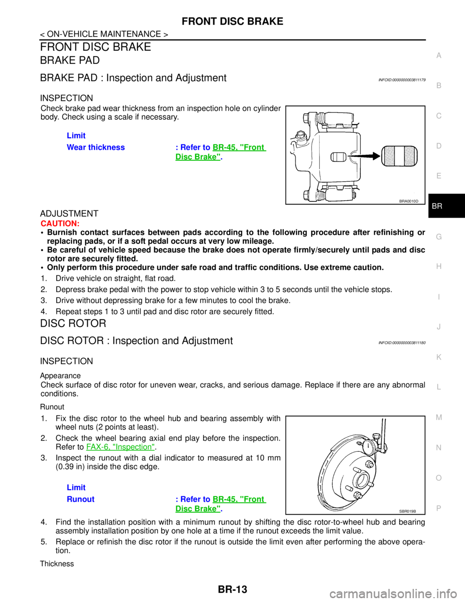
Check brake pad wear thickness from an inspection hole on cylinder
body. Check using a scale if necessary.
ADJUSTMENT
CAUTION:
Burnish contact surfaces between pads according to the following procedure after refinishing or
replacing pads, or if a soft pedal occurs at very low mileage.
Be careful of vehicle speed because the brake does not operate firmly/securely until pads and disc
rotor are securely fitted.
Only perform this procedure under safe road and traffic conditions. Use extreme caution.
1. Drive vehicle on straight, flat road.
2. Depress brake pedal with the power to stop vehicle within 3 to 5 seconds until the vehicle stops.
3. Drive without depressing brake for a few minutes to cool the brake.
4. Repeat steps 1 to 3 until pad and disc rotor are securely fitted.
DISC ROTOR
DISC ROTOR : Inspection and AdjustmentINFOID:0000000003811180
INSPECTION
Appearance
Check surface of disc rotor for uneven wear, cracks, and serious damage. Replace if there are any abnormal
conditions.
Runout
1. Fix the disc rotor to the wheel hub and bearing assembly with
wheel nuts (2 points at least).
2. Check the wheel bearing axial end play before the inspection.
Refer to FA X - 6 , "
Inspection".
3. Inspect the runout with a dial indicator to measured at 10 mm
(0.39 in) inside the disc edge.
4. Find the installation position with a minimum runout by shifting the disc rotor-to-wheel hub and bearing
assembly installation position by one hole at a time if the runout exceeds the limit value.
5. Replace or refinish the disc rotor if the runout is outside the limit even after performing the above opera-
tion.
Thickness
Limit
Wear thickness : Refer to BR-45, "
Front
Disc Brake".
BRA0010D
Limit
Runout : Refer to BR-45, "
Front
Disc Brake".SBR019B
Page 910 of 5121
BR-14
< ON-VEHICLE MAINTENANCE >
FRONT DISC BRAKE
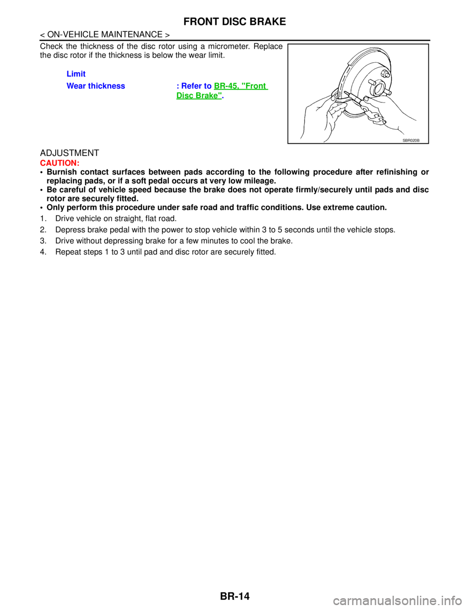
Check the thickness of the disc rotor using a micrometer. Replace
the disc rotor if the thickness is below the wear limit.
ADJUSTMENT
CAUTION:
Burnish contact surfaces between pads according to the following procedure after refinishing or
replacing pads, or if a soft pedal occurs at very low mileage.
Be careful of vehicle speed because the brake does not operate firmly/securely until pads and disc
rotor are securely fitted.
Only perform this procedure under safe road and traffic conditions. Use extreme caution.
1. Drive vehicle on straight, flat road.
2. Depress brake pedal with the power to stop vehicle within 3 to 5 seconds until the vehicle stops.
3. Drive without depressing brake for a few minutes to cool the brake.
4. Repeat steps 1 to 3 until pad and disc rotor are securely fitted.Limit
Wear thickness : Refer to BR-45, "
Front
Disc Brake".
SBR020B
Page 911 of 5121
REAR DISC BRAKE
BR-15
< ON-VEHICLE MAINTENANCE >
C
D
E
G
H
I
J
K
L
MA
B
BR
N
O
P
REAR DISC BRAKE
BRAKE PAD
BRAKE PAD : Inspection and AdjustmentINFOID:0000000003811181
INSPECTION
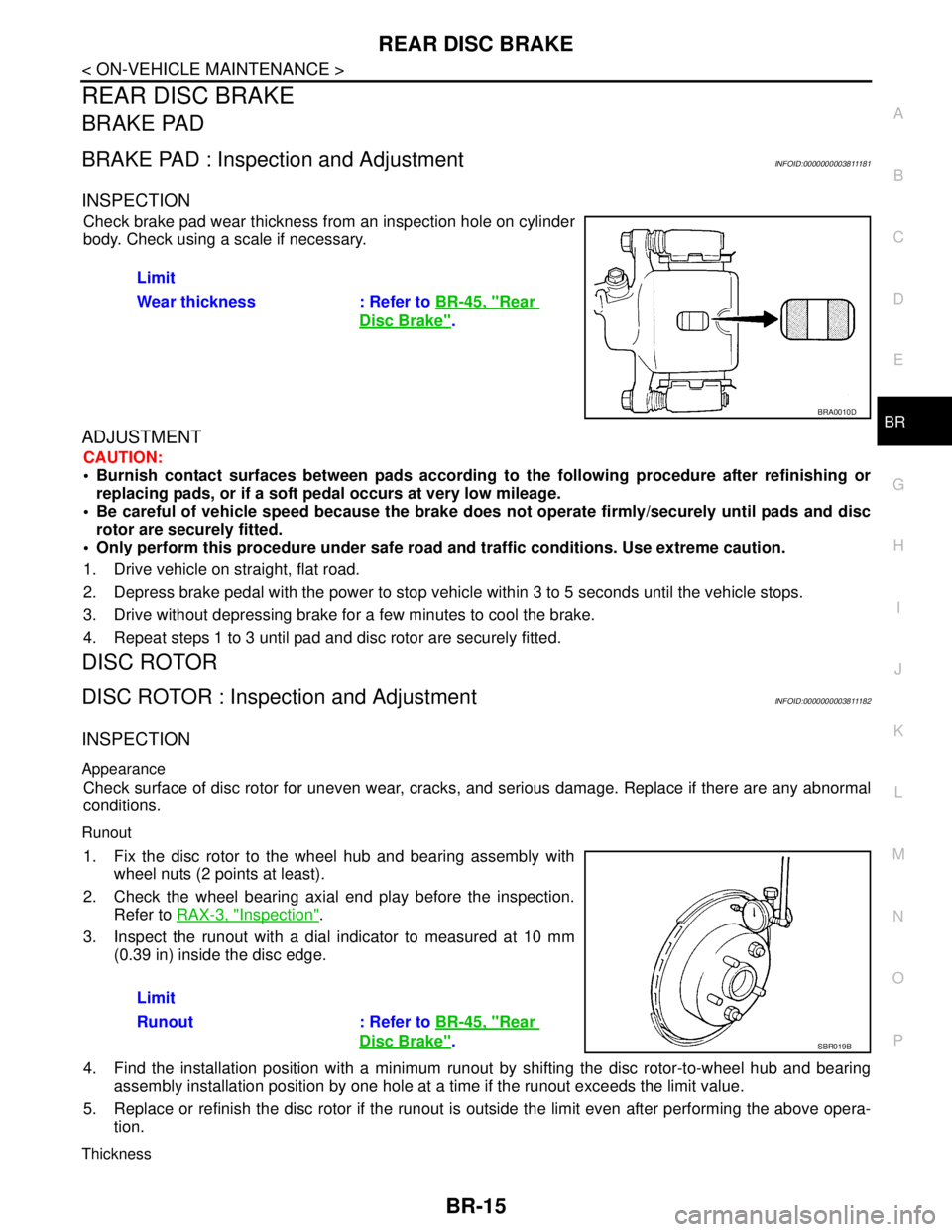
Check brake pad wear thickness from an inspection hole on cylinder
body. Check using a scale if necessary.
ADJUSTMENT
CAUTION:
Burnish contact surfaces between pads according to the following procedure after refinishing or
replacing pads, or if a soft pedal occurs at very low mileage.
Be careful of vehicle speed because the brake does not operate firmly/securely until pads and disc
rotor are securely fitted.
Only perform this procedure under safe road and traffic conditions. Use extreme caution.
1. Drive vehicle on straight, flat road.
2. Depress brake pedal with the power to stop vehicle within 3 to 5 seconds until the vehicle stops.
3. Drive without depressing brake for a few minutes to cool the brake.
4. Repeat steps 1 to 3 until pad and disc rotor are securely fitted.
DISC ROTOR
DISC ROTOR : Inspection and AdjustmentINFOID:0000000003811182
INSPECTION
Appearance
Check surface of disc rotor for uneven wear, cracks, and serious damage. Replace if there are any abnormal
conditions.
Runout
1. Fix the disc rotor to the wheel hub and bearing assembly with
wheel nuts (2 points at least).
2. Check the wheel bearing axial end play before the inspection.
Refer to RAX-3, "
Inspection".
3. Inspect the runout with a dial indicator to measured at 10 mm
(0.39 in) inside the disc edge.
4. Find the installation position with a minimum runout by shifting the disc rotor-to-wheel hub and bearing
assembly installation position by one hole at a time if the runout exceeds the limit value.
5. Replace or refinish the disc rotor if the runout is outside the limit even after performing the above opera-
tion.
Thickness
Limit
Wear thickness : Refer to BR-45, "
Rear
Disc Brake".
BRA0010D
Limit
Runout : Refer to BR-45, "
Rear
Disc Brake".SBR019B
Page 912 of 5121
BR-16
< ON-VEHICLE MAINTENANCE >
REAR DISC BRAKE
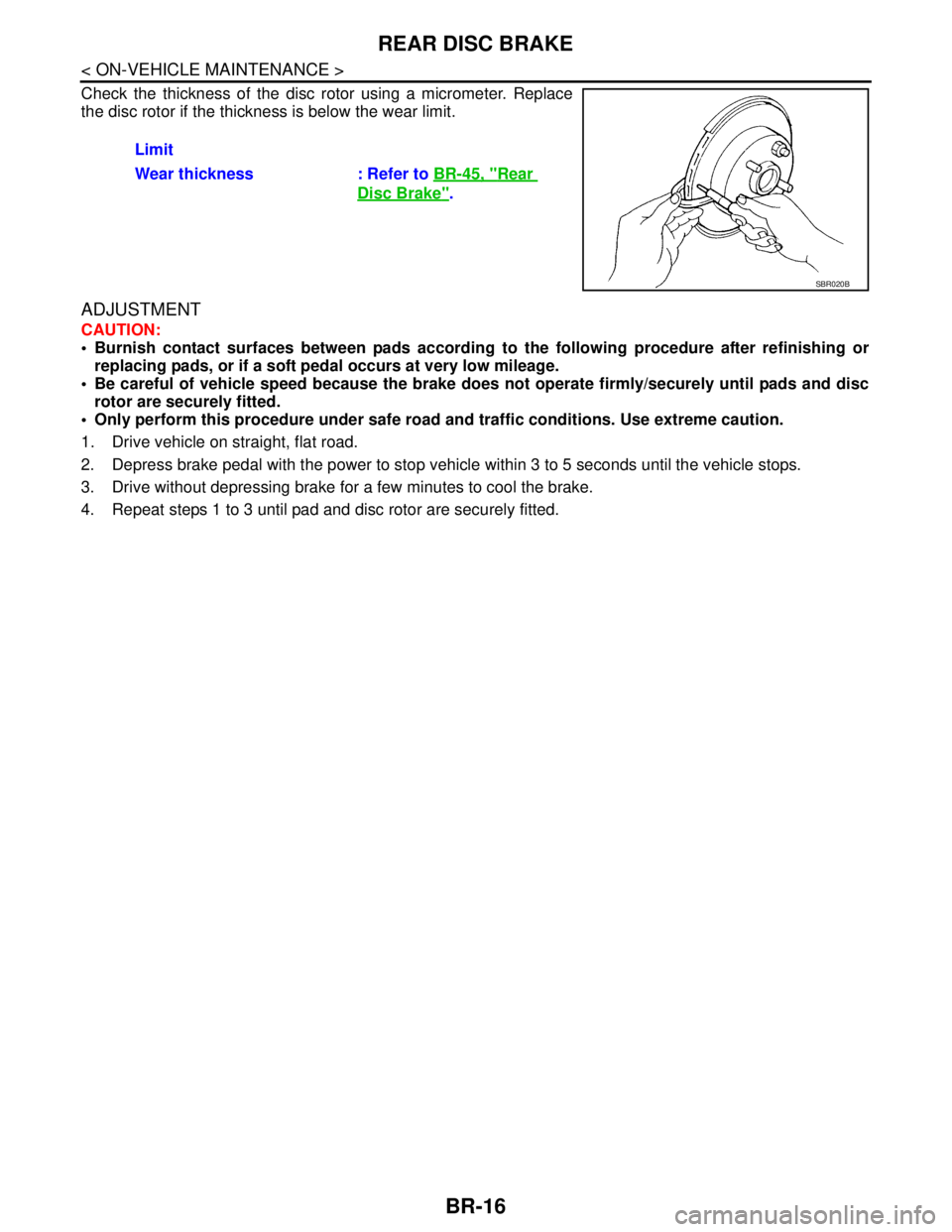
Check the thickness of the disc rotor using a micrometer. Replace
the disc rotor if the thickness is below the wear limit.
ADJUSTMENT
CAUTION:
Burnish contact surfaces between pads according to the following procedure after refinishing or
replacing pads, or if a soft pedal occurs at very low mileage.
Be careful of vehicle speed because the brake does not operate firmly/securely until pads and disc
rotor are securely fitted.
Only perform this procedure under safe road and traffic conditions. Use extreme caution.
1. Drive vehicle on straight, flat road.
2. Depress brake pedal with the power to stop vehicle within 3 to 5 seconds until the vehicle stops.
3. Drive without depressing brake for a few minutes to cool the brake.
4. Repeat steps 1 to 3 until pad and disc rotor are securely fitted.Limit
Wear thickness : Refer to BR-45, "
Rear
Disc Brake".
SBR020B
Page 917 of 5121
BRAKE PIPINGBR-21
< ON-VEHICLE REPAIR >
C
DE
G H
I
J
K L
M A
B
BR
N
O P
FRONT : Removal and InstallationINFOID:0000000003811188
REMOVAL
CAUTION:
Never spill or splash brake fluid on painted surfaces. Brake fluid may seriously damage paint. Wipe it
off immediately and wash with wate r if it gets on a painted surface.
1. Remove tires.
2. Drain brake fluid. Refer to BR-9, "
Draining".
3. Loosen the flare nut with a flare nut wrenc h and separate the brake tube from the hose.
CAUTION:
Never scratch the flare nut and the brake tube.
Never bend sharply, twist or strong ly pull out the brake hoses and tubes.
Cover open end of brake tub es and hoses when disconnecting to prevent entrance of dirt.
4. Remove the union bolt and copper washers, and remove the brake hose from the brake caliper assembly.
5. Remove the lock plate and remove the brake hose.
INSTALLATION
CAUTION:
Never spill or splash brake fluid on painted surfaces. Brake fluid may seriously damage paint. Wipe it
off immediately and wash with wate r if it gets on a painted surface.
1. Assemble the union bolt and the copper washers to the brake hose. CAUTION:
Never reuse the copper washer.
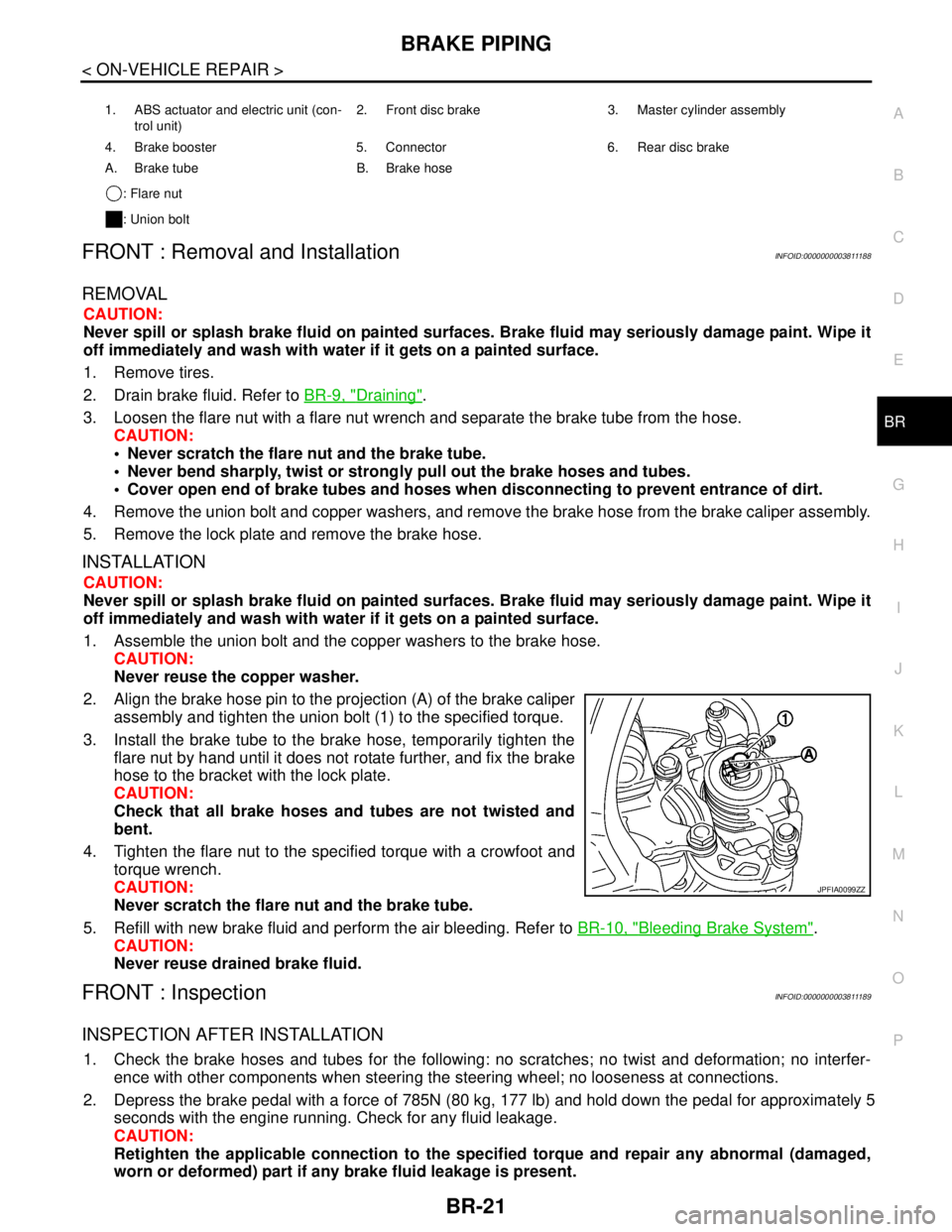
2. Align the brake hose pin to the projection (A) of the brake caliper assembly and tighten the union bolt (1) to the specified torque.
3. Install the brake tube to the brake hose, temporarily tighten the flare nut by hand until it does not rotate further, and fix the brake
hose to the bracket with the lock plate.
CAUTION:
Check that all brake hoses and tubes are not twisted and
bent.
4. Tighten the flare nut to the specified torque with a crowfoot and torque wrench.
CAUTION:
Never scratch the flare nut and the brake tube.
5. Refill with new brake fluid and perform the air bleeding. Refer to BR-10, "
Bleeding Brake System".
CAUTION:
Never reuse drained brake fluid.
FRONT : InspectionINFOID:0000000003811189
INSPECTION AFTER INSTALLATION
1. Check the brake hoses and tubes for the following: no scratches; no twist and deformation; no interfer-
ence with other components when steering the steering wheel; no looseness at connections.
2. Depress the brake pedal with a force of 785N (80 kg, 177 lb) and hold down the pedal for approximately 5
seconds with the engine running. Check for any fluid leakage.
CAUTION:
Retighten the applicable connect ion to the specified torque and repair any abnormal (damaged,
worn or deformed) part if any brake fluid leakage is present.
1. ABS actuator and electric unit (con-
trol unit) 2. Front disc brake 3. Master cylinder assembly
4. Brake booster 5. Connector 6. Rear disc brake
A. Brake tube B. Brake hose : Flare nut
: Union bolt
JPFIA0099ZZ
Page 919 of 5121

BRAKE PIPINGBR-23
< ON-VEHICLE REPAIR >
C
DE
G H
I
J
K L
M A
B
BR
N
O P
REAR : Removal and InstallationINFOID:0000000003811192
REMOVAL
CAUTION:
Never spill or splash brake fluid on painted surfaces. Brake fluid may seriously damage paint. Wipe it
off immediately and wash with wate r if it gets on a painted surface.
1. Remove tires.
2. Drain brake fluid. Refer to BR-9, "
Draining".
3. Loosen the flare nut with a flare nut wrenc h and separate the brake tube from the hose.
CAUTION:
Never scratch the flare nut and the brake tube.
Never sharply bend, twist or strongly pull the brake hoses and tubes.
Cover the open end of brake tubes and hoses wh en disconnecting to prevent entrance of dirt.
4. Remove the union bolt and copper washers, and remove the brake hose from the brake caliper assembly.
5. Remove the lock plate and remove the brake hose from the vehicle.
INSTALLATION
CAUTION:
Never spill or splash brake fluid on painted surfaces. Brake fluid may seriously damage paint. Wipe it
off immediately and wash with wate r if it gets on a painted surface.
1. Assemble the union bolt and the copper washers to the brake hose. CAUTION:
Never reuse copper washer.
2. Install the brake hose L-pin by aligning it with the brake caliper assembly positioning hole, and tighten the union bolt (1) to the
specified torque.
3. Connect the hose to the brake tube, temporarily tighten the flare nut by hand until it does not rotate further, and fix the brake hose
to the bracket with the lock plate.
CAUTION:
Check that the brake hoses and tubes are not twisted and
bent.
4. Tighten the flare nut to the specified torque with a crowfoot and torque wrench.
CAUTION:
Never scratch the flare nut and the brake tube.
5. Refill with new brake fluid and perform the air bleeding. Refer to BR-10, "
Bleeding Brake System".
CAUTION:
Never reuse drained brake fluid.
REAR : InspectionINFOID:0000000003811193
INSPECTION AFTER INSTALLATION
1. Check the brake hoses and tubes for the following: no scratches; no twist and deformation; no interfer-
ence with other components when steering the steering wheel; no looseness at connections.
2. Depress the brake pedal with a force of 785N (80
kg, 177 lb) and hold down the pedal for approximately 5
seconds with the engine running. Check for any fluid leakage.
CAUTION:
1. ABS actuator and electric unit (con- trol unit) 2. Front disc brake 3. Master cylinder assembly
4. Brake booster 5. Connector 6. Rear disc brake
A. Brake tube B. Brake hose : Flare nut
: Union bolt
JPFIA0012ZZ
Page 921 of 5121
BRAKE MASTER CYLINDER
BR-25
< ON-VEHICLE REPAIR >
C
D
E
G
H
I
J
K
L
MA
B
BR
N
O
P
BRAKE MASTER CYLINDER
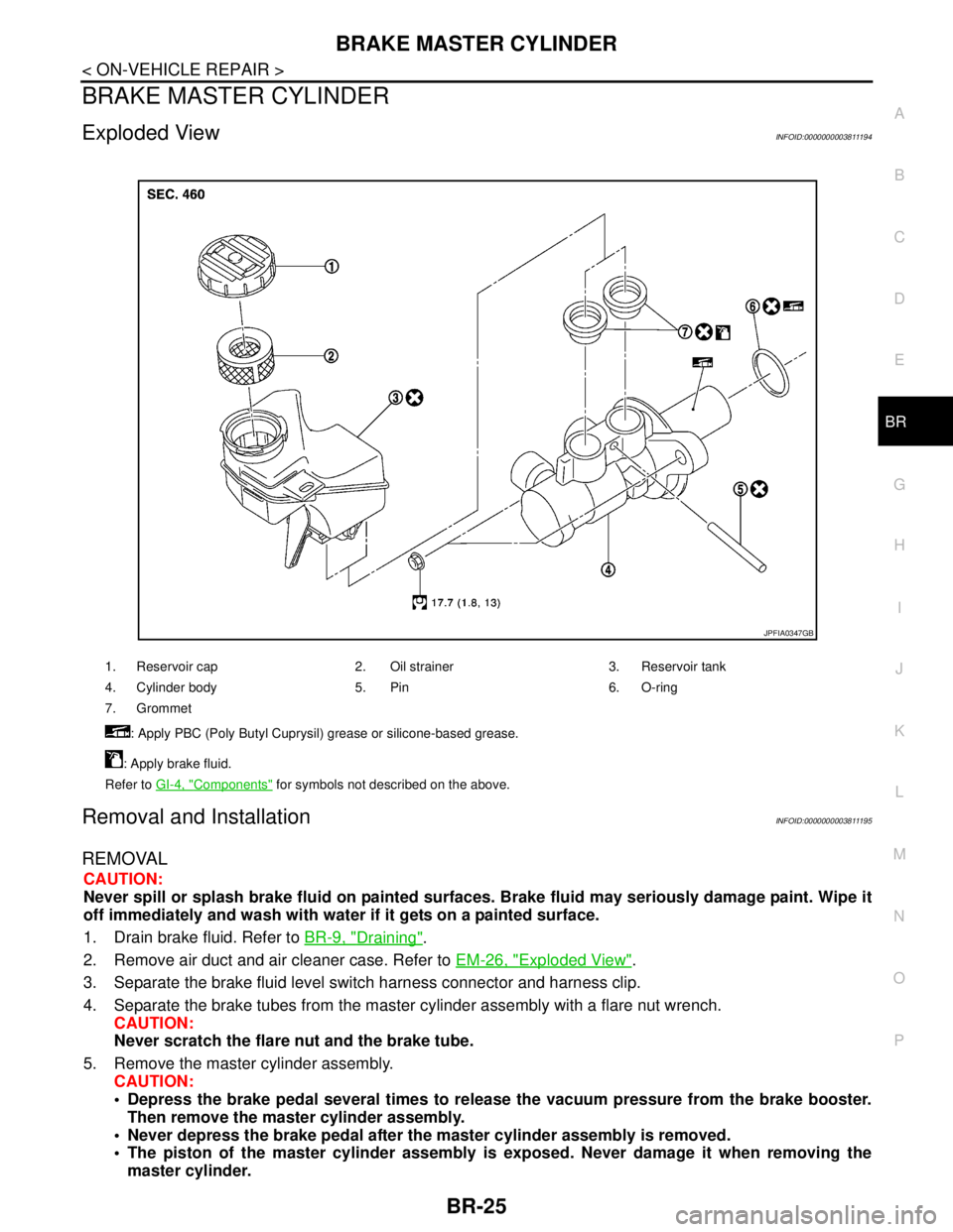
Exploded ViewINFOID:0000000003811194
Removal and InstallationINFOID:0000000003811195
REMOVAL
CAUTION:
Never spill or splash brake fluid on painted surfaces. Brake fluid may seriously damage paint. Wipe it
off immediately and wash with water if it gets on a painted surface.
1. Drain brake fluid. Refer to BR-9, "
Draining".
2. Remove air duct and air cleaner case. Refer to EM-26, "
Exploded View".
3. Separate the brake fluid level switch harness connector and harness clip.
4. Separate the brake tubes from the master cylinder assembly with a flare nut wrench.
CAUTION:
Never scratch the flare nut and the brake tube.
5. Remove the master cylinder assembly.
CAUTION:
Depress the brake pedal several times to release the vacuum pressure from the brake booster.
Then remove the master cylinder assembly.
Never depress the brake pedal after the master cylinder assembly is removed.
The piston of the master cylinder assembly is exposed. Never damage it when removing the
master cylinder.
1. Reservoir cap 2. Oil strainer 3. Reservoir tank
4. Cylinder body 5. Pin 6. O-ring
7. Grommet
: Apply PBC (Poly Butyl Cuprysil) grease or silicone-based grease.
: Apply brake fluid.
Refer to GI-4, "
Components" for symbols not described on the above.
JPFIA0347GB