Int NISSAN TEANA 2008 Service Manual
[x] Cancel search | Manufacturer: NISSAN, Model Year: 2008, Model line: TEANA, Model: NISSAN TEANA 2008Pages: 5121, PDF Size: 69.03 MB
Page 922 of 5121
BR-26
< ON-VEHICLE REPAIR >
BRAKE MASTER CYLINDER
The piston may drop off when pulled out strongly. Never hold the piston. Hold the cylinder body
when handling the master cylinder assembly.
INSTALLATION
CAUTION:
Never spill or splash brake fluid on painted surfaces. Brake fluid may seriously damage paint. Wipe it
off immediately and wash with water if it gets on a painted surface.
Note the following, and install the reverse order of removal.
Never depress the brake pedal after the master cylinder assembly is removed.
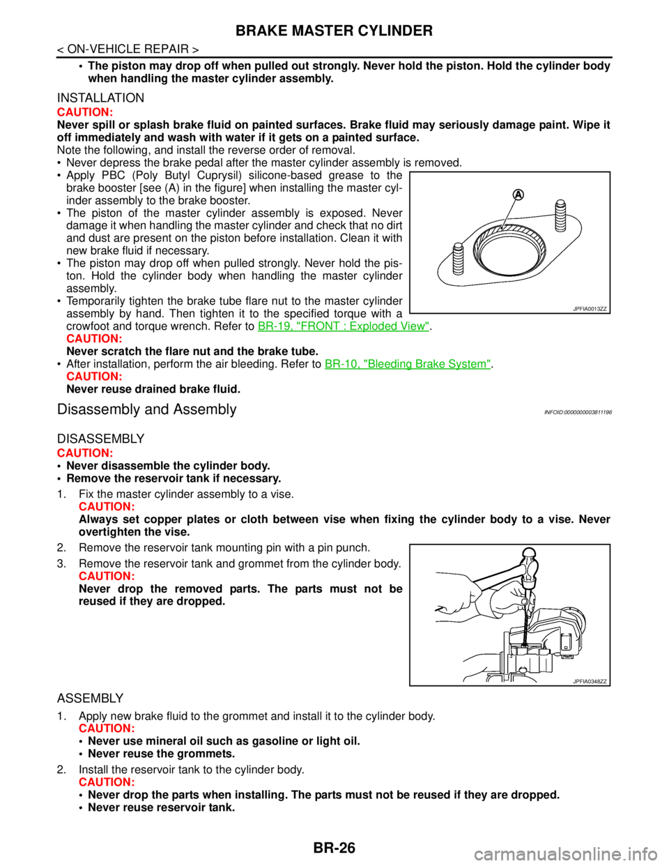
Apply PBC (Poly Butyl Cuprysil) silicone-based grease to the
brake booster [see (A) in the figure] when installing the master cyl-
inder assembly to the brake booster.
The piston of the master cylinder assembly is exposed. Never
damage it when handling the master cylinder and check that no dirt
and dust are present on the piston before installation. Clean it with
new brake fluid if necessary.
The piston may drop off when pulled strongly. Never hold the pis-
ton. Hold the cylinder body when handling the master cylinder
assembly.
Temporarily tighten the brake tube flare nut to the master cylinder
assembly by hand. Then tighten it to the specified torque with a
crowfoot and torque wrench. Refer to BR-19, "
FRONT : Exploded View".
CAUTION:
Never scratch the flare nut and the brake tube.
After installation, perform the air bleeding. Refer to BR-10, "
Bleeding Brake System".
CAUTION:
Never reuse drained brake fluid.
Disassembly and AssemblyINFOID:0000000003811196
DISASSEMBLY
CAUTION:
Never disassemble the cylinder body.
Remove the reservoir tank if necessary.
1. Fix the master cylinder assembly to a vise.
CAUTION:
Always set copper plates or cloth between vise when fixing the cylinder body to a vise. Never
overtighten the vise.
2. Remove the reservoir tank mounting pin with a pin punch.
3. Remove the reservoir tank and grommet from the cylinder body.
CAUTION:
Never drop the removed parts. The parts must not be
reused if they are dropped.
ASSEMBLY
1. Apply new brake fluid to the grommet and install it to the cylinder body.
CAUTION:
Never use mineral oil such as gasoline or light oil.
Never reuse the grommets.
2. Install the reservoir tank to the cylinder body.
CAUTION:
Never drop the parts when installing. The parts must not be reused if they are dropped.
Never reuse reservoir tank.
JPFIA0013ZZ
JPFIA0348ZZ
Page 923 of 5121
BRAKE MASTER CYLINDER
BR-27
< ON-VEHICLE REPAIR >
C
D
E
G
H
I
J
K
L
MA
B
BR
N
O
P
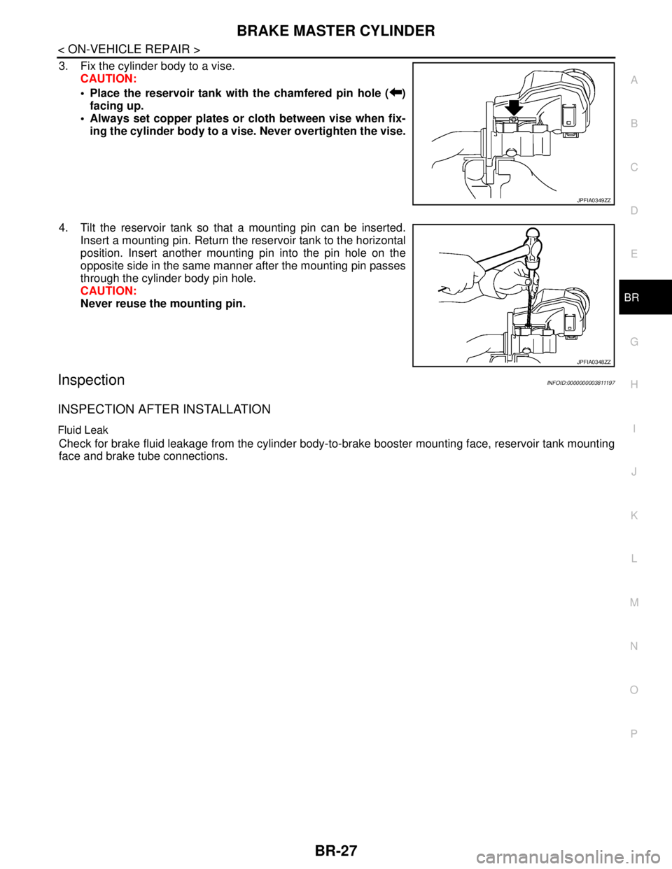
3. Fix the cylinder body to a vise.
CAUTION:
Place the reservoir tank with the chamfered pin hole ( )
facing up.
Always set copper plates or cloth between vise when fix-
ing the cylinder body to a vise. Never overtighten the vise.
4. Tilt the reservoir tank so that a mounting pin can be inserted.
Insert a mounting pin. Return the reservoir tank to the horizontal
position. Insert another mounting pin into the pin hole on the
opposite side in the same manner after the mounting pin passes
through the cylinder body pin hole.
CAUTION:
Never reuse the mounting pin.
InspectionINFOID:0000000003811197
INSPECTION AFTER INSTALLATION
Fluid Leak
Check for brake fluid leakage from the cylinder body-to-brake booster mounting face, reservoir tank mounting
face and brake tube connections.
JPFIA0349ZZ
JPFIA0348ZZ
Page 925 of 5121

BRAKE BOOSTER
BR-29
< ON-VEHICLE REPAIR >
C
D
E
G
H
I
J
K
L
MA
B
BR
N
O
P
Replace the clevis pin if it is damaged. Refer to BR-18, "Inspection and Adjustment".
After installation, perform the air bleeding. Refer to BR-10, "
Bleeding Brake System".
CAUTION:
Never reuse drained brake fluid.
Inspection and AdjustmentINFOID:0000000003811200
INSPECTION AFTER REMOVAL
Output Rod Length Inspection
1. With a handy vacuum pump, apply vacuum pressure of −66.7
kPa (−500 mmHg, −19.70 inHg, –0.667 bar) to the brake
booster.
2. Check the output rod length (A).
Input Rod Length Inspection
1. Loosen the lock nut (1) and adjust the input rod (2) to the speci-
fied length (B).
2. Tighten the lock nut to the specified torque.
INSPECTION AFTER INSTALLATION
Operation
Depress the brake pedal several times at 5-second intervals with the
engine stopped. Start the engine with the brake pedal fully
depressed. Check that the clearance between brake pedal and dash
lower pane decreases.
NOTE:
A slight impact with a small click may be felt on the pedal when the
brake pedal is fully depressed. This is a normal phenomenon due to
the brake system operation.
Air Tight
Standard
A: Refer to BR-45, "
Brake Booster".
JPFIA0021ZZ
Standard
B: Refer to BR-45, "
Brake Booster".
JPFIA0020ZZ
BRA0037D
Page 926 of 5121

BR-30
< ON-VEHICLE REPAIR >
BRAKE BOOSTER
Idle the engine for 1 minute to apply vacuum to the brake booster,
and stop the engine. Then depress the brake pedal several times
at 5-second intervals until the accumulated vacuum is released to
atmospheric pressure. Check that the clearance between brake
pedal and dash lower panel gradually increases (A → B → C) each
time the brake pedal is depressed during this operation.
Depress the brake pedal with the engine running. Then stop the
engine while holding down the brake pedal. Check that the brake
pedal stroke does not change after holding down the brake pedal
for 30 seconds or more.
NOTE:
A slight impact with a small click may be felt on the pedal when the
brake pedal is fully depressed. This is a normal phenomenon due
to the brake system operation.
ADJUSTMENT AFTER INSTALLATION
Perform the brake pedal adjustment after installing the brake pedal assembly. Refer to BR-6, "Inspection and
Adjustment".
JPFIA0043ZZ
JPFIA0044ZZ
Page 927 of 5121
VACUUM LINES
BR-31
< ON-VEHICLE REPAIR >
C
D
E
G
H
I
J
K
L
MA
B
BR
N
O
P
VACUUM LINES
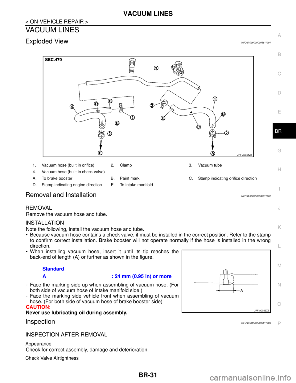
Exploded ViewINFOID:0000000003811201
Removal and InstallationINFOID:0000000003811202
REMOVAL
Remove the vacuum hose and tube.
INSTALLATION
Note the following, install the vacuum hose and tube.
Because vacuum hose contains a check valve, it must be installed in the correct position. Refer to the stamp
to confirm correct installation. Brake booster will not operate normally if the hose is installed in the wrong
direction.
When installing vacuum hose, insert it until its tip reaches the
back-end of length (A) or further as shown in the figure.
- Face the marking side up when assembling of vacuum hose. (For
both side of vacuum hose of intake manifold side.)
- Face the marking side vehicle front when assembling of vacuum
hose. (For both side of vacuum hose of brake booster side)
CAUTION:
Never use lubricating oil during assembly.
InspectionINFOID:0000000003811203
INSPECTION AFTER REMOVAL
Appearance
Check for correct assembly, damage and deterioration.
Check Valve Airtightness
1. Vacuum hose (built in orifice) 2. Clamp 3. Vacuum tube
4. Vacuum hose (built in check valve)
A. To brake booster B. Paint mark C. Stamp indicating orifice direction
D. Stamp indicating engine direction E. To intake manifold
JPFIA0351ZZ
Standard
A : 24 mm (0.95 in) or more
JPFIA0023ZZ
Page 933 of 5121

FRONT DISC BRAKE
BR-37
< ON-VEHICLE REPAIR >
C
D
E
G
H
I
J
K
L
MA
B
BR
N
O
P
5. Place a wooden block as shown in the figure, and blow air from
union bolt mounting hole to remove piston and piston boot.
CAUTION:
Never get fingers caught in the piston.
6. Remove piston seal from cylinder body using suitable tool.
CAUTION:
Be careful not to damage a cylinder inner wall.
7. Remove bleeder valve and cap.
ASSEMBLY
1. Install bleeder valve and cap.
2. Apply rubber grease to piston seal (1), and install to cylinder
body.
CAUTION:
Never reuse piston seal.
3. Apply rubber grease to piston boot (1). Cover the piston (2) end
with piston boot, and then install cylinder side lip on piston boot
securely into a groove on cylinder body.
CAUTION:
Never reuse piston boot.
MAA0272D
JPFIA0038ZZ
JPFIA0039ZZ
JPFIA0040ZZ
Page 934 of 5121
BR-38
< ON-VEHICLE REPAIR >
FRONT DISC BRAKE
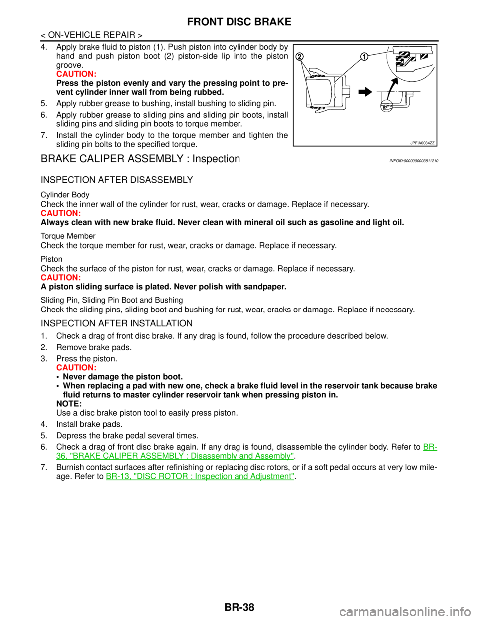
4. Apply brake fluid to piston (1). Push piston into cylinder body by
hand and push piston boot (2) piston-side lip into the piston
groove.
CAUTION:
Press the piston evenly and vary the pressing point to pre-
vent cylinder inner wall from being rubbed.
5. Apply rubber grease to bushing, install bushing to sliding pin.
6. Apply rubber grease to sliding pins and sliding pin boots, install
sliding pins and sliding pin boots to torque member.
7. Install the cylinder body to the torque member and tighten the
sliding pin bolts to the specified torque.
BRAKE CALIPER ASSEMBLY : InspectionINFOID:0000000003811210
INSPECTION AFTER DISASSEMBLY
Cylinder Body
Check the inner wall of the cylinder for rust, wear, cracks or damage. Replace if necessary.
CAUTION:
Always clean with new brake fluid. Never clean with mineral oil such as gasoline and light oil.
Torque Member
Check the torque member for rust, wear, cracks or damage. Replace if necessary.
Piston
Check the surface of the piston for rust, wear, cracks or damage. Replace if necessary.
CAUTION:
A piston sliding surface is plated. Never polish with sandpaper.
Sliding Pin, Sliding Pin Boot and Bushing
Check the sliding pins, sliding boot and bushing for rust, wear, cracks or damage. Replace if necessary.
INSPECTION AFTER INSTALLATION
1. Check a drag of front disc brake. If any drag is found, follow the procedure described below.
2. Remove brake pads.
3. Press the piston.
CAUTION:
Never damage the piston boot.
When replacing a pad with new one, check a brake fluid level in the reservoir tank because brake
fluid returns to master cylinder reservoir tank when pressing piston in.
NOTE:
Use a disc brake piston tool to easily press piston.
4. Install brake pads.
5. Depress the brake pedal several times.
6. Check a drag of front disc brake again. If any drag is found, disassemble the cylinder body. Refer to BR-
36, "BRAKE CALIPER ASSEMBLY : Disassembly and Assembly".
7. Burnish contact surfaces after refinishing or replacing disc rotors, or if a soft pedal occurs at very low mile-
age. Refer to BR-13, "
DISC ROTOR : Inspection and Adjustment".
JPFIA0034ZZ
Page 939 of 5121
REAR DISC BRAKE
BR-43
< ON-VEHICLE REPAIR >
C
D
E
G
H
I
J
K
L
MA
B
BR
N
O
P
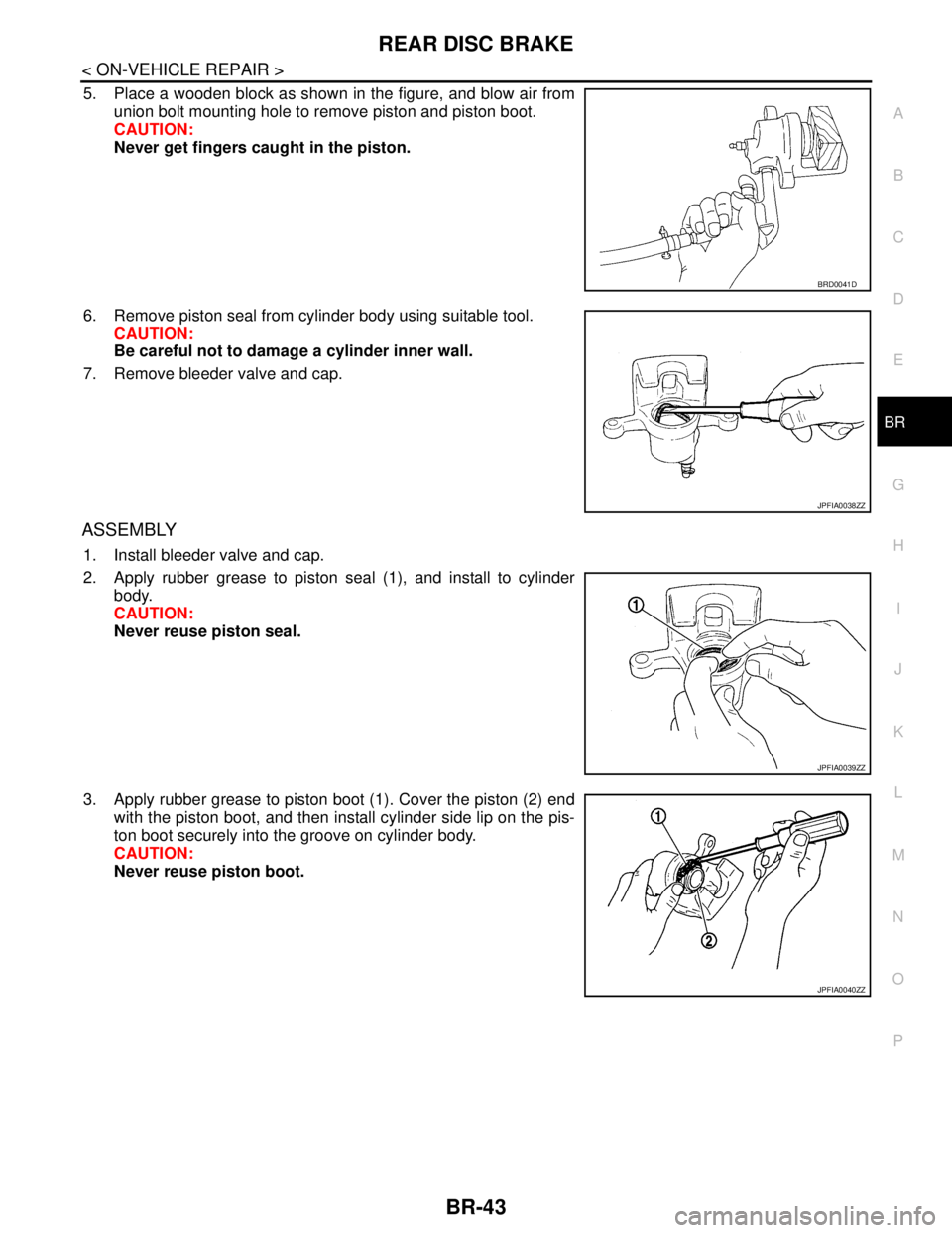
5. Place a wooden block as shown in the figure, and blow air from
union bolt mounting hole to remove piston and piston boot.
CAUTION:
Never get fingers caught in the piston.
6. Remove piston seal from cylinder body using suitable tool.
CAUTION:
Be careful not to damage a cylinder inner wall.
7. Remove bleeder valve and cap.
ASSEMBLY
1. Install bleeder valve and cap.
2. Apply rubber grease to piston seal (1), and install to cylinder
body.
CAUTION:
Never reuse piston seal.
3. Apply rubber grease to piston boot (1). Cover the piston (2) end
with the piston boot, and then install cylinder side lip on the pis-
ton boot securely into the groove on cylinder body.
CAUTION:
Never reuse piston boot.
BRD0041D
JPFIA0038ZZ
JPFIA0039ZZ
JPFIA0040ZZ
Page 940 of 5121
BR-44
< ON-VEHICLE REPAIR >
REAR DISC BRAKE
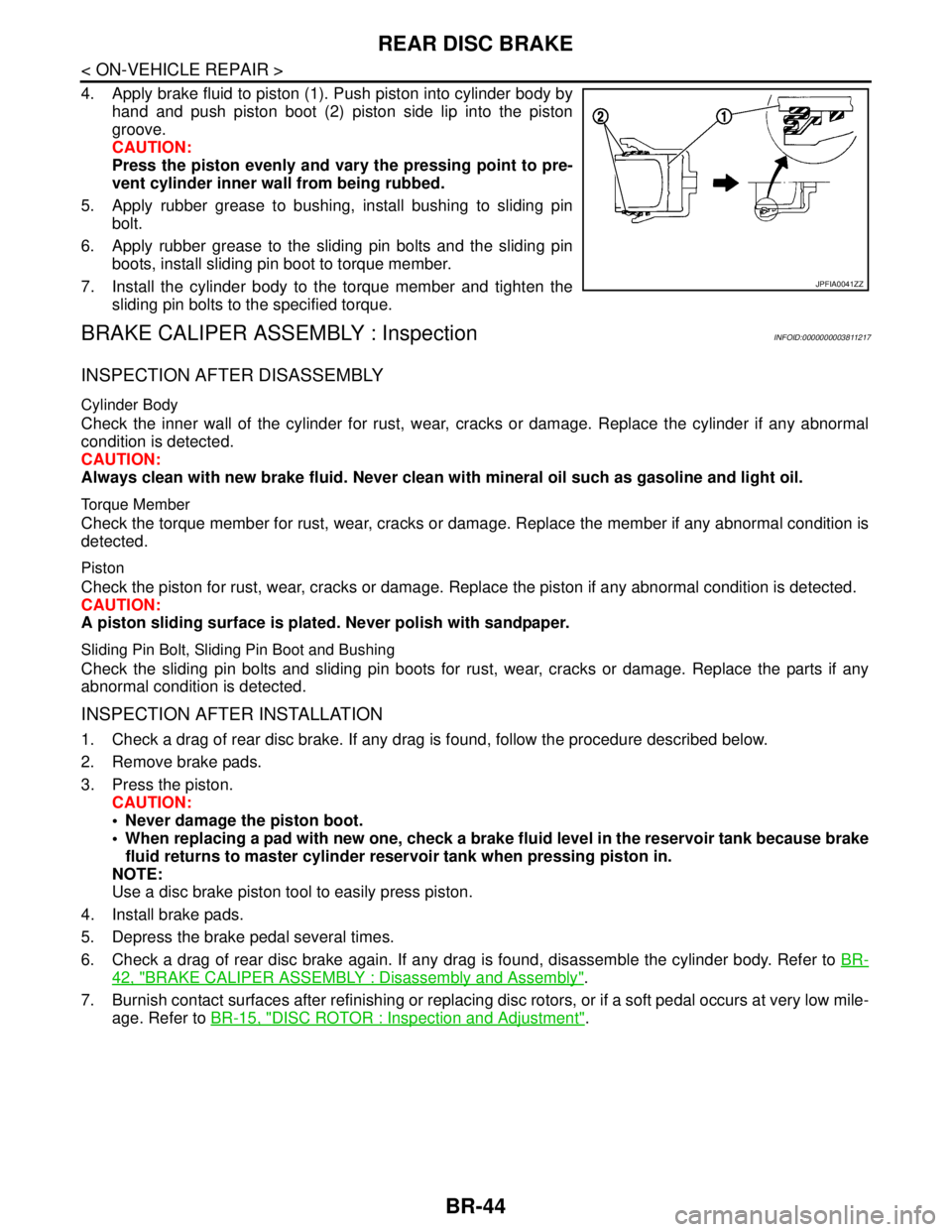
4. Apply brake fluid to piston (1). Push piston into cylinder body by
hand and push piston boot (2) piston side lip into the piston
groove.
CAUTION:
Press the piston evenly and vary the pressing point to pre-
vent cylinder inner wall from being rubbed.
5. Apply rubber grease to bushing, install bushing to sliding pin
bolt.
6. Apply rubber grease to the sliding pin bolts and the sliding pin
boots, install sliding pin boot to torque member.
7. Install the cylinder body to the torque member and tighten the
sliding pin bolts to the specified torque.
BRAKE CALIPER ASSEMBLY : InspectionINFOID:0000000003811217
INSPECTION AFTER DISASSEMBLY
Cylinder Body
Check the inner wall of the cylinder for rust, wear, cracks or damage. Replace the cylinder if any abnormal
condition is detected.
CAUTION:
Always clean with new brake fluid. Never clean with mineral oil such as gasoline and light oil.
Torque Member
Check the torque member for rust, wear, cracks or damage. Replace the member if any abnormal condition is
detected.
Piston
Check the piston for rust, wear, cracks or damage. Replace the piston if any abnormal condition is detected.
CAUTION:
A piston sliding surface is plated. Never polish with sandpaper.
Sliding Pin Bolt, Sliding Pin Boot and Bushing
Check the sliding pin bolts and sliding pin boots for rust, wear, cracks or damage. Replace the parts if any
abnormal condition is detected.
INSPECTION AFTER INSTALLATION
1. Check a drag of rear disc brake. If any drag is found, follow the procedure described below.
2. Remove brake pads.
3. Press the piston.
CAUTION:
Never damage the piston boot.
When replacing a pad with new one, check a brake fluid level in the reservoir tank because brake
fluid returns to master cylinder reservoir tank when pressing piston in.
NOTE:
Use a disc brake piston tool to easily press piston.
4. Install brake pads.
5. Depress the brake pedal several times.
6. Check a drag of rear disc brake again. If any drag is found, disassemble the cylinder body. Refer to BR-
42, "BRAKE CALIPER ASSEMBLY : Disassembly and Assembly".
7. Burnish contact surfaces after refinishing or replacing disc rotors, or if a soft pedal occurs at very low mile-
age. Refer to BR-15, "
DISC ROTOR : Inspection and Adjustment".
JPFIA0041ZZ
Page 943 of 5121
BRC-2
Description ..............................................................36
DTC Logic ...............................................................36
Diagnosis Procedure ..............................................36
Component Inspection ............................................37
U1000, U1002 CAN COMM CIRCUIT ...............38
Description ..............................................................38
DTC Logic ...............................................................38
Diagnosis Procedure ..............................................38
POWER SUPPLY AND GROUND CIRCUIT .....39
Description ..............................................................39
Diagnosis Procedure ..............................................39
ABS WARNING LAMP ......................................40
Description ..............................................................40
Component Function Check ...................................40
Diagnosis Procedure ..............................................40
BRAKE WARNING LAMP .................................41
Description ..............................................................41
Component Function Check ...................................41
Diagnosis Procedure ..............................................41
ECU DIAGNOSIS ........................................42
ABS ACTUATOR AND ELECTRIC UNIT
(CONTROL UNIT) ..............................................
42
Reference Value .....................................................42
Wiring Diagram - BRAKE CONTROL SYSTEM - ...44
Fail-Safe .................................................................47
DTC No. Index ........................................................48
SYMPTOM DIAGNOSIS .............................49
EXCESSIVE ABS FUNCTION OPERATION
FREQUENCY .....................................................
49
Diagnosis Procedure ..............................................49
UNEXPECTED PEDAL REACTION ..................50
Diagnosis Procedure ..............................................50
THE BRAKING DISTANCE IS LONG ...............51
Diagnosis Procedure ..............................................51
ABS FUNCTION DOES NOT OPERATE ..........52
Diagnosis Procedure ..............................................52
PEDAL VIBRATION OR ABS OPERATION
SOUND OCCURS ..............................................
53
Diagnosis Procedure ..............................................53
NORMAL OPERATING CONDITION ................54
Description ..............................................................54
PRECAUTION .............................................55
PRECAUTIONS .................................................55
Precaution for Supplemental Restraint System
(SRS) "AIR BAG" and "SEAT BELT PRE-TEN-
SIONER" .................................................................
55
Precaution for Procedure without Cowl Top Cover ...55
Precaution for Brake System ..................................55
Precaution for Brake Control ...................................56
Precautions for Harness Repair ..............................56
ON-VEHICLE REPAIR ...............................57
WHEEL SENSOR ..............................................57
FRONT WHEEL SENSOR ........................................57
FRONT WHEEL SENSOR : Exploded View ...........57
FRONT WHEEL SENSOR : Removal and Instal-
lation .......................................................................
57
REAR WHEEL SENSOR ...........................................58
REAR WHEEL SENSOR : Exploded View .............58
REAR WHEEL SENSOR : Removal and Installa-
tion ..........................................................................
58
SENSOR ROTOR ..............................................59
FRONT SENSOR ROTOR ........................................59
FRONT SENSOR ROTOR : Exploded View ...........59
FRONT SENSOR ROTOR : Removal and Instal-
lation .......................................................................
59
REAR SENSOR ROTOR ...........................................59
REAR SENSOR ROTOR : Exploded View .............59
REAR SENSOR ROTOR : Removal and Installa-
tion ..........................................................................
59
ABS ACTUATOR AND ELECTRIC UNIT
(CONTROL UNIT) ..............................................
60
Exploded View ........................................................60
Removal and Installation .........................................60
VDC/TCS/ABS
BASIC INSPECTION ..................................
62
DIAGNOSIS AND REPAIR WORK FLOW ........62
Work Flow ...............................................................62
Diagnostic Work Sheet ...........................................65
INSPECTION AND ADJUSTMENT ...................66
ADDITIONAL SERVICE WHEN REPLACING
CONTROL UNIT ........................................................
66
ADDITIONAL SERVICE WHEN REPLACING
CONTROL UNIT : Description ................................
66
ADDITIONAL SERVICE WHEN REPLACING
CONTROL UNIT : Special Repair Requirement .....
66
ADJUSTMENT OF STEERING ANGLE SENSOR
NEUTRAL POSITION ................................................
66
ADJUSTMENT OF STEERING ANGLE SENSOR
NEUTRAL POSITION : Description ........................
66
ADJUSTMENT OF STEERING ANGLE SENSOR
NEUTRAL POSITION : Special Repair Require-
ment ........................................................................
66
FUNCTION DIAGNOSIS ............................68
VDC ....................................................................68