Int NISSAN TEANA 2008 Service Manual
[x] Cancel search | Manufacturer: NISSAN, Model Year: 2008, Model line: TEANA, Model: NISSAN TEANA 2008Pages: 5121, PDF Size: 69.03 MB
Page 1143 of 5121

CO-20
< ON-VEHICLE REPAIR >
WATER PUMP
b. Screw M8 bolts [pitch: 1.25 mm (0.0492 in) length: approxi-
mately 50 mm (1.97 in)] into water pumps upper and lower
mounting bolt holes until they reach timing chain case. Then,
alternately tighten each bolt for a half turn, and pull out water
pump.
CAUTION:
Pull straight out while preventing vane from contacting
socket in installation area.
Remove water pump without causing sprocket to contact
timing chain.
c. Remove M8 bolts and O-rings from water pump.
CAUTION:
Never disassemble water pump.
INSTALLATION
1. Install new O-rings to water pump.
Apply engine oil and engine coolant to O-rings as shown in the
figure.
Locate O-ring with white paint mark to engine front side.
2. Install water pump.
CAUTION:
Never allow cylinder block to nip O-rings when installing
water pump.
Check that timing chain and water pump sprocket are
engaged.
Insert water pump by tightening mounting bolts alternately and
evenly.
3. Install timing chain tensioner (primary) as follows:
a. Turn crankshaft pulley clockwise so that timing chain on the tim-
ing chain tensioner (primary) side is loose.
JLC357B
PBIC1397E
SLC031B
PBIC4820E
Page 1144 of 5121
WATER PUMP
CO-21
< ON-VEHICLE REPAIR >
C
D
E
F
G
H
I
J
K
L
MA
CO
N
P O
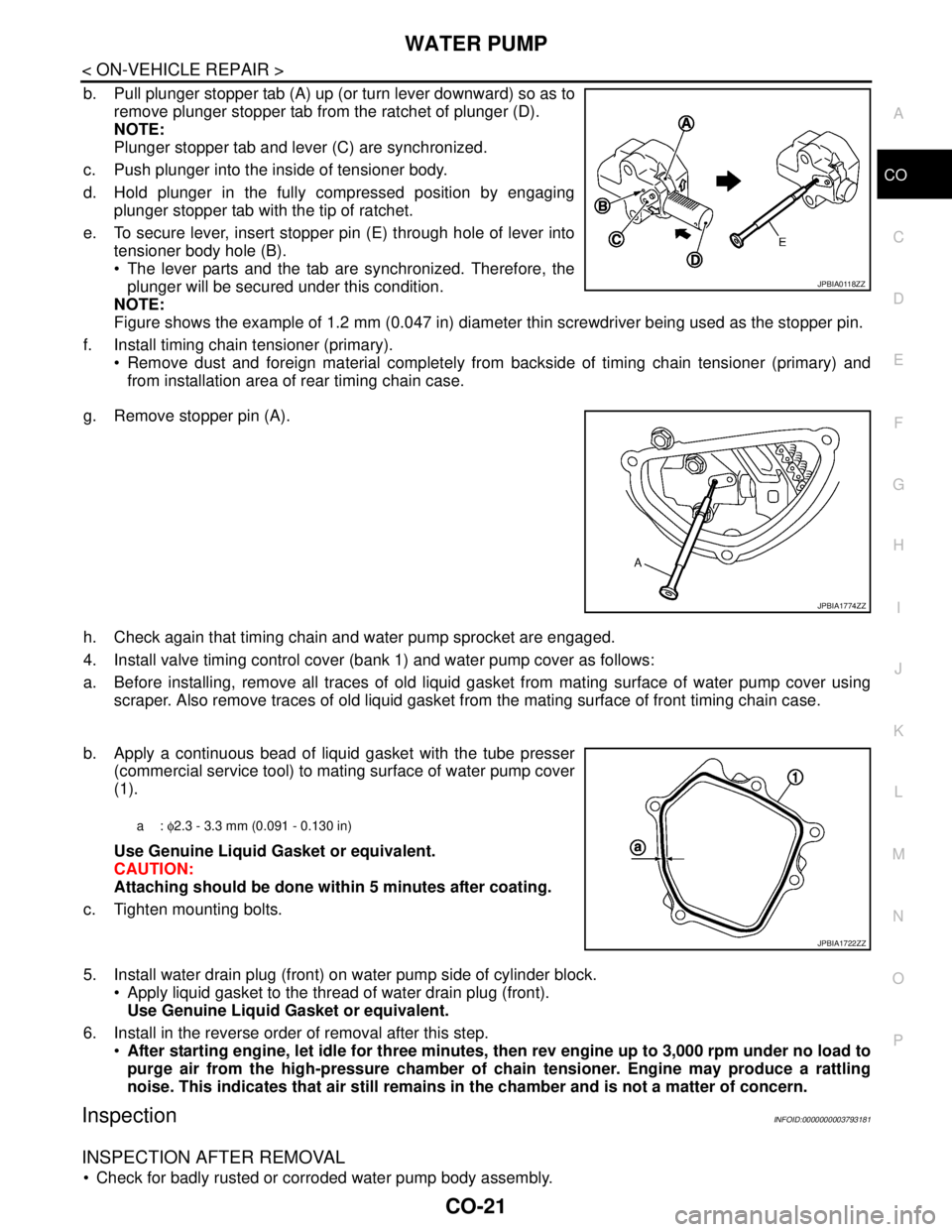
b. Pull plunger stopper tab (A) up (or turn lever downward) so as to
remove plunger stopper tab from the ratchet of plunger (D).
NOTE:
Plunger stopper tab and lever (C) are synchronized.
c. Push plunger into the inside of tensioner body.
d. Hold plunger in the fully compressed position by engaging
plunger stopper tab with the tip of ratchet.
e. To secure lever, insert stopper pin (E) through hole of lever into
tensioner body hole (B).
The lever parts and the tab are synchronized. Therefore, the
plunger will be secured under this condition.
NOTE:
Figure shows the example of 1.2 mm (0.047 in) diameter thin screwdriver being used as the stopper pin.
f. Install timing chain tensioner (primary).
Remove dust and foreign material completely from backside of timing chain tensioner (primary) and
from installation area of rear timing chain case.
g. Remove stopper pin (A).
h. Check again that timing chain and water pump sprocket are engaged.
4. Install valve timing control cover (bank 1) and water pump cover as follows:
a. Before installing, remove all traces of old liquid gasket from mating surface of water pump cover using
scraper. Also remove traces of old liquid gasket from the mating surface of front timing chain case.
b. Apply a continuous bead of liquid gasket with the tube presser
(commercial service tool) to mating surface of water pump cover
(1).
Use Genuine Liquid Gasket or equivalent.
CAUTION:
Attaching should be done within 5 minutes after coating.
c. Tighten mounting bolts.
5. Install water drain plug (front) on water pump side of cylinder block.
Apply liquid gasket to the thread of water drain plug (front).
Use Genuine Liquid Gasket or equivalent.
6. Install in the reverse order of removal after this step.
After starting engine, let idle for three minutes, then rev engine up to 3,000 rpm under no load to
purge air from the high-pressure chamber of chain tensioner. Engine may produce a rattling
noise. This indicates that air still remains in the chamber and is not a matter of concern.
InspectionINFOID:0000000003793181
INSPECTION AFTER REMOVAL
Check for badly rusted or corroded water pump body assembly.
JPBIA0118ZZ
JPBIA1774ZZ
a: φ2.3 - 3.3 mm (0.091 - 0.130 in)
JPBIA1722ZZ
Page 1146 of 5121
WATER INLET AND THERMOSTAT ASSEMBLY
CO-23
< ON-VEHICLE REPAIR >
C
D
E
F
G
H
I
J
K
L
MA
CO
N
P O
WATER INLET AND THERMOSTAT ASSEMBLY
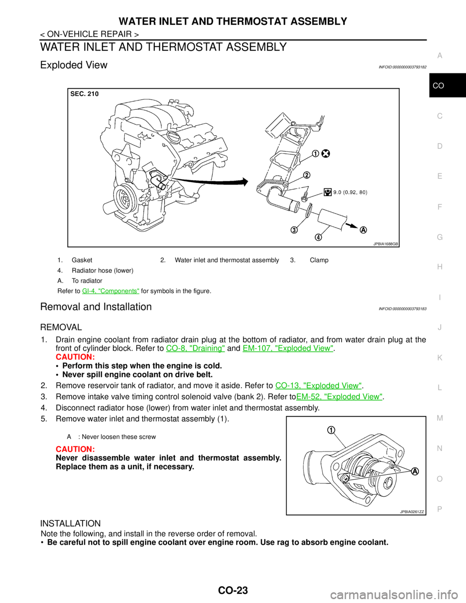
Exploded ViewINFOID:0000000003793182
Removal and InstallationINFOID:0000000003793183
REMOVAL
1. Drain engine coolant from radiator drain plug at the bottom of radiator, and from water drain plug at the
front of cylinder block. Refer to CO-8, "
Draining" and EM-107, "Exploded View".
CAUTION:
Perform this step when the engine is cold.
Never spill engine coolant on drive belt.
2. Remove reservoir tank of radiator, and move it aside. Refer to CO-13, "
Exploded View".
3. Remove intake valve timing control solenoid valve (bank 2). Refer toEM-52, "
Exploded View".
4. Disconnect radiator hose (lower) from water inlet and thermostat assembly.
5. Remove water inlet and thermostat assembly (1).
CAUTION:
Never disassemble water inlet and thermostat assembly.
Replace them as a unit, if necessary.
INSTALLATION
Note the following, and install in the reverse order of removal.
Be careful not to spill engine coolant over engine room. Use rag to absorb engine coolant.
1. Gasket 2. Water inlet and thermostat assembly 3. Clamp
4. Radiator hose (lower)
A. To radiator
Refer to GI-4, "
Components" for symbols in the figure.
JPBIA1688GB
A : Never loosen these screw
JPBIA0261ZZ
Page 1149 of 5121
CO-26
< ON-VEHICLE REPAIR >
WATER OUTLET AND WATER PIPING
5. Remove CVT fluid charging pipe and CVT fluid level gauge. Refer to TM-332, "Exploded View" (VQ25DE)
or TM-168, "
Exploded View" (VQ35DE).
6. Move CVT control cable aside. Refer to TM-319, "
Exploded View" (VQ25DE) or TM-157, "Exploded View"
(VQ35DE).
7. Remove vacuum pipe (front) mounting bolt from water outlet. Refer to EM-67, "
Exploded View".
8. Remove radiator hose (upper) from water outlet.
9. Remove water hoses and heater hoses.
10. Disconnect harness connectors, and move harness to aside.
11. Remove engine coolant temperature sensor as necessary.
CAUTION:
Be careful not to damage engine coolant temperature sensor.
12. Remove water outlet, heater pipe, water bypass pipe and water connector.
INSTALLATION
Note the following, and install in the reverse order of removal.
Securely insert each hose, and install clamp at a position where it does not interfere with the pipe bulge.
When inserting water bypass pipe and heater pipe into water connector, apply neutral detergent to O-ring.
InspectionINFOID:0000000003793187
INSPECTION AFTER INSTALLATION
Check for leakage of engine coolant using the radiator cap tester adapter (commercial service tool) and the
radiator cap tester (commercial service tool). Refer to CO-8, "
Inspection".
Start and warm up the engine. Visually check that there is no leakage of engine coolant.
Page 1150 of 5121
SERVICE DATA AND SPECIFICATIONS (SDS)
CO-27
< SERVICE DATA AND SPECIFICATIONS (SDS)
C
D
E
F
G
H
I
J
K
L
MA
CO
N
P O
SERVICE DATA AND SPECIFICATIONS (SDS)
SERVICE DATA AND SPECIFICATIONS (SDS)
Periodical Maintenance SpecificationINFOID:0000000003793188
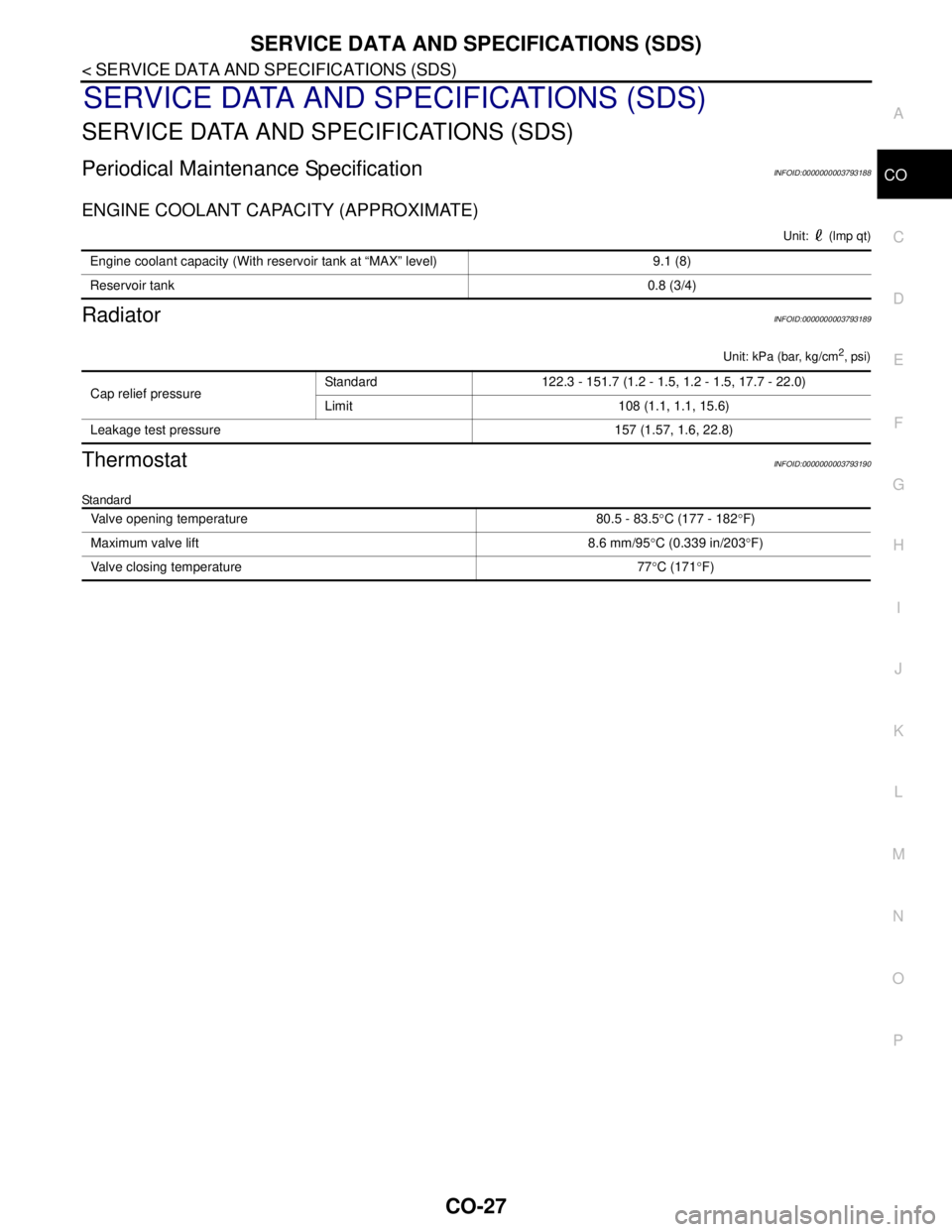
ENGINE COOLANT CAPACITY (APPROXIMATE)
Unit: (lmp qt)
RadiatorINFOID:0000000003793189
Unit: kPa (bar, kg/cm2, psi)
ThermostatINFOID:0000000003793190
Standard
Engine coolant capacity (With reservoir tank at “MAX” level) 9.1 (8)
Reservoir tank0.8 (3/4)
Cap relief pressureStandard 122.3 - 151.7 (1.2 - 1.5, 1.2 - 1.5, 17.7 - 22.0)
Limit 108 (1.1, 1.1, 15.6)
Leakage test pressure 157 (1.57, 1.6, 22.8)
Valve opening temperature 80.5 - 83.5°C (177 - 182°F)
Maximum valve lift 8.6 mm/95°C (0.339 in/203°F)
Valve closing temperature 77°C (171°F)
Page 1152 of 5121
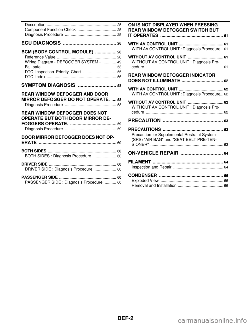
DEF-2
Description ..............................................................25
Component Function Check ...................................25
Diagnosis Procedure ..............................................25
ECU DIAGNOSIS ........................................26
BCM (BODY CONTROL MODULE) ..................26
Reference Value .....................................................26
Wiring Diagram - DEFOGGER SYSTEM - .............49
Fail-safe ..................................................................53
DTC Inspection Priority Chart ..............................55
DTC Index ..............................................................56
SYMPTOM DIAGNOSIS .............................58
REAR WINDOW DEFOGGER AND DOOR
MIRROR DEFOGGER DO NOT OPERATE. .....
58
Diagnosis Procedure ..............................................58
REAR WINDOW DEFOGGER DOES NOT
OPERATE BUT BOTH DOOR MIRROR DE-
FOGGERS OPERATE. ......................................
59
Diagnosis Procedure ..............................................59
DOOR MIRROR DEFOGGER DOES NOT OP-
ERATE ...............................................................
60
BOTH SIDES .............................................................60
BOTH SIDES : Diagnosis Procedure .....................60
DRIVER SIDE ............................................................60
DRIVER SIDE : Diagnosis Procedure ....................60
PASSENGER SIDE ...................................................60
PASSENGER SIDE : Diagnosis Procedure ...........60
ON IS NOT DISPLAYED WHEN PRESSING
REAR WINDOW DEFOGGER SWITCH BUT
IT OPERATES ...................................................
61
WITH AV CONTROL UNIT ........................................61
WITH AV CONTROL UNIT : Diagnosis Procedure ...61
WITHOUT AV CONTROL UNIT ................................61
WITHOUT AV CONTROL UNIT : Diagnosis Pro-
cedure .....................................................................
61
REAR WINDOW DEFOGGER INDICATOR
DOES NOT ILLUMINATE ..................................
62
WITH AV CONTROL UNIT ........................................62
WITH AV CONTROL UNIT : Diagnosis Procedure ...62
WITHOUT AV CONTROL UNIT ................................62
WITHOUT AV CONTROL UNIT : Diagnosis Pro-
cedure .....................................................................
62
PRECAUTION ............................................63
PRECAUTIONS .................................................63
Precaution for Supplemental Restraint System
(SRS) "AIR BAG" and "SEAT BELT PRE-TEN-
SIONER" .................................................................
63
ON-VEHICLE REPAIR ...............................64
FILAMENT .........................................................64
Inspection and Repair .............................................64
CONDENSER ....................................................66
Exploded View ........................................................66
Removal and Installation .........................................66
Page 1153 of 5121
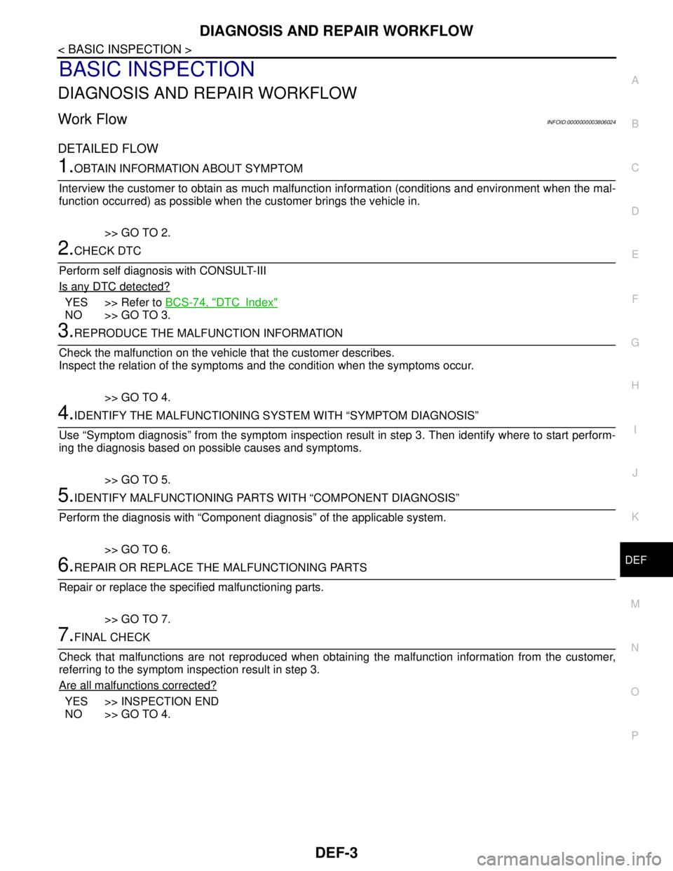
DIAGNOSIS AND REPAIR WORKFLOW
DEF-3
< BASIC INSPECTION >
C
D
E
F
G
H
I
J
K
MA
B
DEF
N
O
P
BASIC INSPECTION
DIAGNOSIS AND REPAIR WORKFLOW
Work FlowINFOID:0000000003806024
DETAILED FLOW
1.OBTAIN INFORMATION ABOUT SYMPTOM
Interview the customer to obtain as much malfunction information (conditions and environment when the mal-
function occurred) as possible when the customer brings the vehicle in.
>> GO TO 2.
2.CHECK DTC
Perform self diagnosis with CONSULT-III
Is any DTC detected?
YES >> Refer to BCS-74, "DTCIndex"
NO >> GO TO 3.
3.REPRODUCE THE MALFUNCTION INFORMATION
Check the malfunction on the vehicle that the customer describes.
Inspect the relation of the symptoms and the condition when the symptoms occur.
>> GO TO 4.
4.IDENTIFY THE MALFUNCTIONING SYSTEM WITH “SYMPTOM DIAGNOSIS”
Use “Symptom diagnosis” from the symptom inspection result in step 3. Then identify where to start perform-
ing the diagnosis based on possible causes and symptoms.
>> GO TO 5.
5.IDENTIFY MALFUNCTIONING PARTS WITH “COMPONENT DIAGNOSIS”
Perform the diagnosis with “Component diagnosis” of the applicable system.
>> GO TO 6.
6.REPAIR OR REPLACE THE MALFUNCTIONING PARTS
Repair or replace the specified malfunctioning parts.
>> GO TO 7.
7.FINAL CHECK
Check that malfunctions are not reproduced when obtaining the malfunction information from the customer,
referring to the symptom inspection result in step 3.
Are all malfunctions corrected?
YES >> INSPECTION END
NO >> GO TO 4.
Page 1158 of 5121
DEF-8
< FUNCTION DIAGNOSIS >
DIAGNOSIS SYSTEM (BCM)
DIAGNOSIS SYSTEM (BCM)
COMMON ITEM
COMMON ITEM : CONSULT-III Function (BCM - COMMON ITEM)INFOID:0000000003940040
APPLICATION ITEM
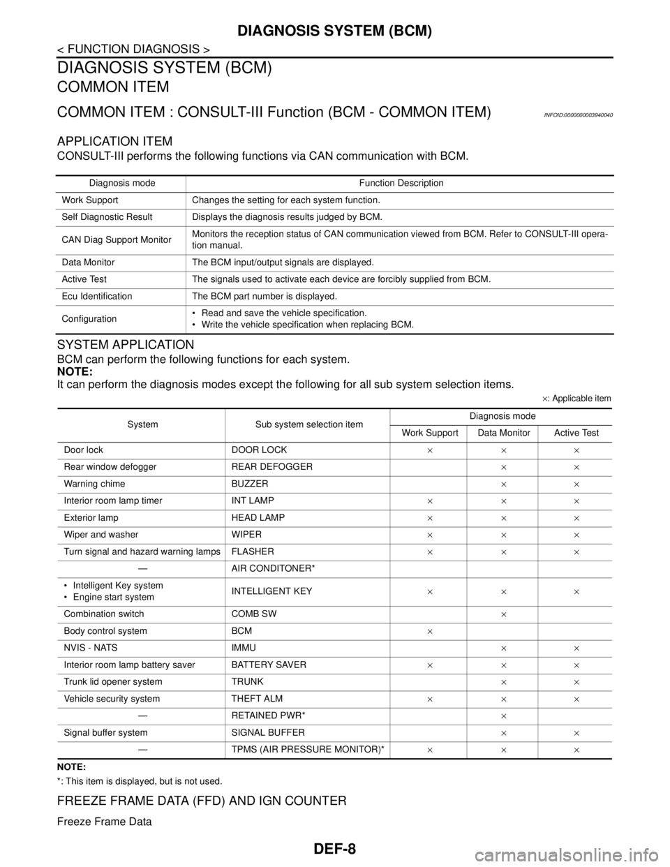
CONSULT-III performs the following functions via CAN communication with BCM.
SYSTEM APPLICATION
BCM can perform the following functions for each system.
NOTE:
It can perform the diagnosis modes except the following for all sub system selection items.
×: Applicable item
NOTE:
*: This item is displayed, but is not used.
FREEZE FRAME DATA (FFD) AND IGN COUNTER
Freeze Frame Data
Diagnosis mode Function Description
Work Support Changes the setting for each system function.
Self Diagnostic Result Displays the diagnosis results judged by BCM.
CAN Diag Support MonitorMonitors the reception status of CAN communication viewed from BCM. Refer to CONSULT-III opera-
tion manual.
Data Monitor The BCM input/output signals are displayed.
Active Test The signals used to activate each device are forcibly supplied from BCM.
Ecu Identification The BCM part number is displayed.
Configuration Read and save the vehicle specification.
Write the vehicle specification when replacing BCM.
System Sub system selection itemDiagnosis mode
Work Support Data Monitor Active Test
Door lock DOOR LOCK×××
Rear window defogger REAR DEFOGGER××
Warning chime BUZZER××
Interior room lamp timer INT LAMP×××
Exterior lamp HEAD LAMP×××
Wiper and washer WIPER×××
Turn signal and hazard warning lamps FLASHER×××
— AIR CONDITONER*
Intelligent Key system
Engine start systemINTELLIGENT KEY×××
Combination switch COMB SW×
Body control system BCM×
NVIS - NATS IMMU××
Interior room lamp battery saver BATTERY SAVER×××
Trunk lid opener system TRUNK××
Vehicle security system THEFT ALM×××
— RETAINED PWR*×
Signal buffer system SIGNAL BUFFER××
— TPMS (AIR PRESSURE MONITOR)*×××
Page 1165 of 5121
REAR WINDOW DEFOGGER RELAY
DEF-15
< COMPONENT DIAGNOSIS >
C
D
E
F
G
H
I
J
K
MA
B
DEF
N
O
P
4.CHECK REAR WINDOW DEFOGGER RELAY
1. Disconnect rear window defogger relay,
2. Check rear window defogger relay.
Refer to DEF-15, "
Component Inspection"
Is the inspection result normal?
YES >> GO TO 5.
NO >> Replace rear window defogger relay.
5.CHECK FUSE BLOCK (J/B)
1. Install the rear window defogger relay.
2. Turn ignition switch ON.
3. Check voltage between fuse block (J/B) (fuse block side) and ground.
Is the inspection result normal?
YES >> GO TO 6.
NO >> Repair or replace fuse block (J/B).
6.CHECK INTERMITTENT INCIDENT
Check intermittent incident.
Refer to GI-35, "
Intermittent Incident"
>> INSPECTION END
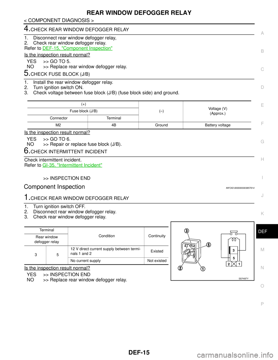
Component InspectionINFOID:0000000003857614
1.CHECK REAR WINDOW DEFOGGER RELAY
1. Turn ignition switch OFF.
2. Disconnect rear window defogger relay.
3. Check rear window defogger relay.
Is the inspection result normal?
YES >> INSPECTION END
NO >> Replace rear window defogger relay.
(+)
(–)Voltage (V)
(Approx.) Fuse block (J/B)
Connector Terminal
M2 4B Ground Battery voltage
Te r m i n a l
Condition Continuity
Rear window
defogger relay
3512 V direct current supply between termi-
nals 1 and 2Existed
No current supply Not existed
SEF497Y
Page 1167 of 5121
REAR WINDOW DEFOGGER
DEF-17
< COMPONENT DIAGNOSIS >
C
D
E
F
G
H
I
J
K
MA
B
DEF
N
O
P
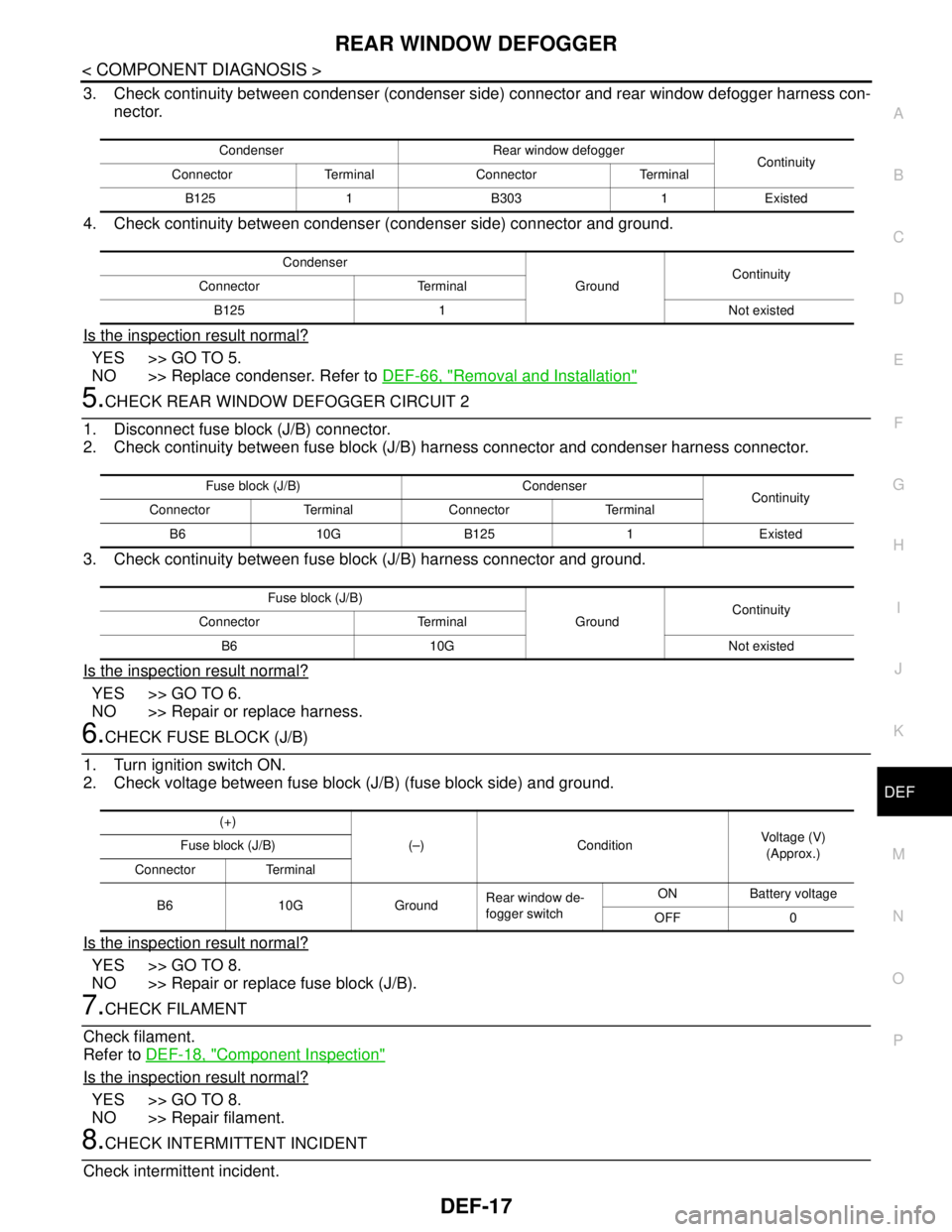
3. Check continuity between condenser (condenser side) connector and rear window defogger harness con-
nector.
4. Check continuity between condenser (condenser side) connector and ground.
Is the inspection result normal?
YES >> GO TO 5.
NO >> Replace condenser. Refer to DEF-66, "
Removal and Installation"
5.CHECK REAR WINDOW DEFOGGER CIRCUIT 2
1. Disconnect fuse block (J/B) connector.
2. Check continuity between fuse block (J/B) harness connector and condenser harness connector.
3. Check continuity between fuse block (J/B) harness connector and ground.
Is the inspection result normal?
YES >> GO TO 6.
NO >> Repair or replace harness.
6.CHECK FUSE BLOCK (J/B)
1. Turn ignition switch ON.
2. Check voltage between fuse block (J/B) (fuse block side) and ground.
Is the inspection result normal?
YES >> GO TO 8.
NO >> Repair or replace fuse block (J/B).
7.CHECK FILAMENT
Check filament.
Refer to DEF-18, "
Component Inspection"
Is the inspection result normal?
YES >> GO TO 8.
NO >> Repair filament.
8.CHECK INTERMITTENT INCIDENT
Check intermittent incident.
Condenser Rear window defogger
Continuity
Connector Terminal Connector Terminal
B125 1 B303 1 Existed
Condenser
GroundContinuity
Connector Terminal
B125 1 Not existed
Fuse block (J/B) Condenser
Continuity
Connector Terminal Connector Terminal
B6 10G B125 1 Existed
Fuse block (J/B)
GroundContinuity
Connector Terminal
B6 10G Not existed
(+)
(–) ConditionVoltage (V)
(Approx.) Fuse block (J/B)
Connector Terminal
B6 10G GroundRear window de-
fogger switchON Battery voltage
OFF 0