NISSAN TEANA 2008 Service Manual
Manufacturer: NISSAN, Model Year: 2008, Model line: TEANA, Model: NISSAN TEANA 2008Pages: 5121, PDF Size: 69.03 MB
Page 3371 of 5121
MWI
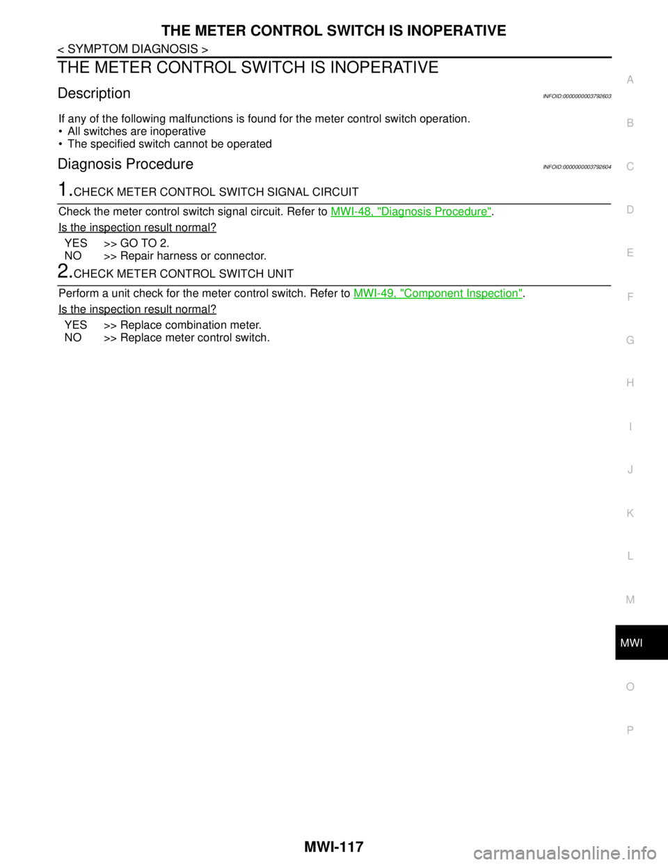
THE METER CONTROL SWITCH IS INOPERATIVE
MWI-117
< SYMPTOM DIAGNOSIS >
C
D
E
F
G
H
I
J
K
L
MB A
O
P
THE METER CONTROL SWITCH IS INOPERATIVE
DescriptionINFOID:0000000003792603
If any of the following malfunctions is found for the meter control switch operation.
All switches are inoperative
The specified switch cannot be operated
Diagnosis ProcedureINFOID:0000000003792604
1.CHECK METER CONTROL SWITCH SIGNAL CIRCUIT
Check the meter control switch signal circuit. Refer to MWI-48, "
Diagnosis Procedure".
Is the inspection result normal?
YES >> GO TO 2.
NO >> Repair harness or connector.
2.CHECK METER CONTROL SWITCH UNIT
Perform a unit check for the meter control switch. Refer to MWI-49, "
Component Inspection".
Is the inspection result normal?
YES >> Replace combination meter.
NO >> Replace meter control switch.
Page 3372 of 5121
MWI-118
< SYMPTOM DIAGNOSIS >
THE OIL PRESSURE WARNING LAMP DOES NOT TURN ON
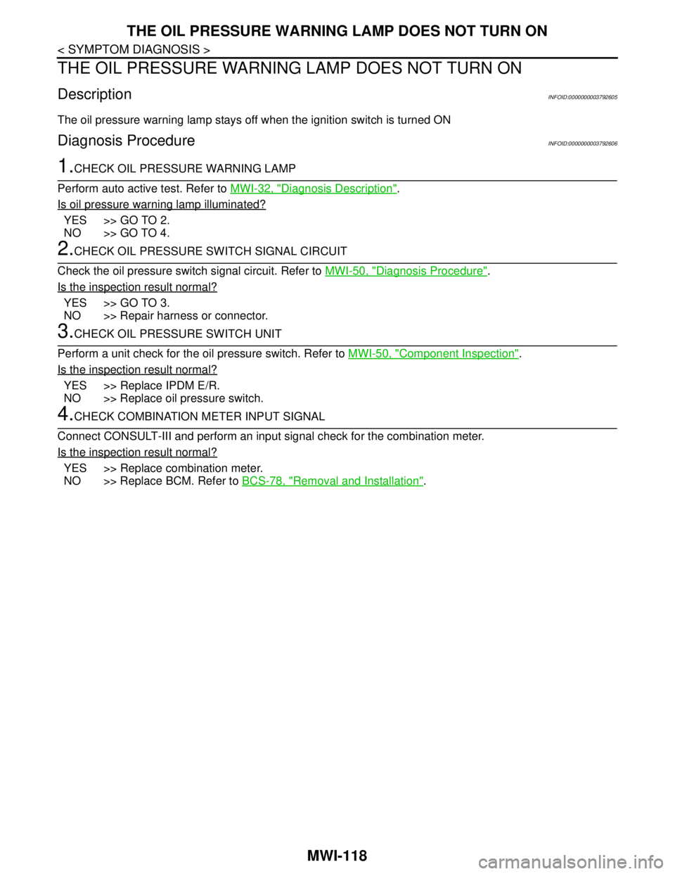
THE OIL PRESSURE WARNING LAMP DOES NOT TURN ON
DescriptionINFOID:0000000003792605
The oil pressure warning lamp stays off when the ignition switch is turned ON
Diagnosis ProcedureINFOID:0000000003792606
1.CHECK OIL PRESSURE WARNING LAMP
Perform auto active test. Refer to MWI-32, "
Diagnosis Description".
Is oil pressure warning lamp illuminated?
YES >> GO TO 2.
NO >> GO TO 4.
2.CHECK OIL PRESSURE SWITCH SIGNAL CIRCUIT
Check the oil pressure switch signal circuit. Refer to MWI-50, "
Diagnosis Procedure".
Is the inspection result normal?
YES >> GO TO 3.
NO >> Repair harness or connector.
3.CHECK OIL PRESSURE SWITCH UNIT
Perform a unit check for the oil pressure switch. Refer to MWI-50, "
Component Inspection".
Is the inspection result normal?
YES >> Replace IPDM E/R.
NO >> Replace oil pressure switch.
4.CHECK COMBINATION METER INPUT SIGNAL
Connect CONSULT-III and perform an input signal check for the combination meter.
Is the inspection result normal?
YES >> Replace combination meter.
NO >> Replace BCM. Refer to BCS-78, "
Removal and Installation".
Page 3373 of 5121
MWI
THE OIL PRESSURE WARNING LAMP DOES NOT TURN OFF
MWI-119
< SYMPTOM DIAGNOSIS >
C
D
E
F
G
H
I
J
K
L
MB A
O
P
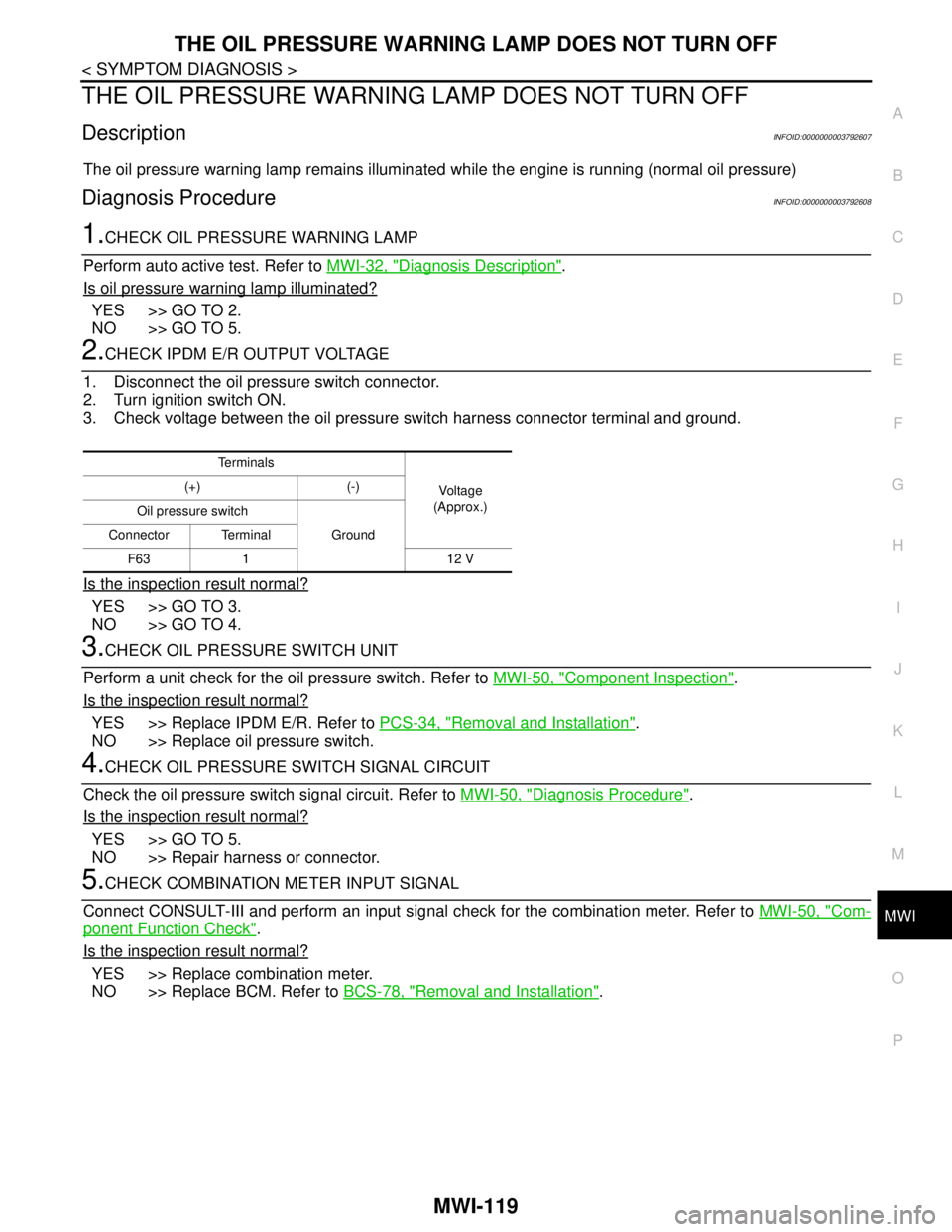
THE OIL PRESSURE WARNING LAMP DOES NOT TURN OFF
DescriptionINFOID:0000000003792607
The oil pressure warning lamp remains illuminated while the engine is running (normal oil pressure)
Diagnosis ProcedureINFOID:0000000003792608
1.CHECK OIL PRESSURE WARNING LAMP
Perform auto active test. Refer to MWI-32, "
Diagnosis Description".
Is oil pressure warning lamp illuminated?
YES >> GO TO 2.
NO >> GO TO 5.
2.CHECK IPDM E/R OUTPUT VOLTAGE
1. Disconnect the oil pressure switch connector.
2. Turn ignition switch ON.
3. Check voltage between the oil pressure switch harness connector terminal and ground.
Is the inspection result normal?
YES >> GO TO 3.
NO >> GO TO 4.
3.CHECK OIL PRESSURE SWITCH UNIT
Perform a unit check for the oil pressure switch. Refer to MWI-50, "
Component Inspection".
Is the inspection result normal?
YES >> Replace IPDM E/R. Refer to PCS-34, "Removal and Installation".
NO >> Replace oil pressure switch.
4.CHECK OIL PRESSURE SWITCH SIGNAL CIRCUIT
Check the oil pressure switch signal circuit. Refer to MWI-50, "
Diagnosis Procedure".
Is the inspection result normal?
YES >> GO TO 5.
NO >> Repair harness or connector.
5.CHECK COMBINATION METER INPUT SIGNAL
Connect CONSULT-III and perform an input signal check for the combination meter. Refer to MWI-50, "
Com-
ponent Function Check".
Is the inspection result normal?
YES >> Replace combination meter.
NO >> Replace BCM. Refer to BCS-78, "
Removal and Installation".
Te r m i n a l s
Voltag e
(Approx.) (+) (-)
Oil pressure switch
Ground Connector Terminal
F63 1 12 V
Page 3374 of 5121

MWI-120
< SYMPTOM DIAGNOSIS >
THE PARKING BRAKE RELEASE WARNING CONTINUES DISPLAYING, OR
DOES NOT DISPLAY
THE PARKING BRAKE RELEASE WARNING CONTINUES DISPLAYING,
OR DOES NOT DISPLAY
DescriptionINFOID:0000000003792609
The parking brake warning is displayed during vehicle travel even though the parking brake is released
The parking brake warning is not displayed even though driving the vehicle with the parking brake applied
Diagnosis ProcedureINFOID:0000000003792610
1.CHECK PARKING BRAKE WARNING LAMP OPERATION
1. Start engine.
2. Check the operation of the parking brake warning lamp when operating the parking brake.
Is the inspection result normal?
YES >> Replace combination meter.
NO >> GO TO 2.
2.CHECK PARKING BRAKE SWITCH SIGNAL CIRCUIT
1. Turn ignition switch OFF.
2. Check the parking brake switch signal circuit. Refer to MWI-52, "
Diagnosis Procedure".
Is the inspection result normal?
YES >> GO TO 3.
NO >> Repair harness or connector.
3.CHECK PARKING BRAKE SWITCH UNIT
Perform a unit check for the parking brake switch. Refer to BRC-124, "
Component Inspection".
Is the inspection result normal?
YES >> Replace combination meter.
NO >> Replace parking brake switch.
Condition Warning lamp status
When parking brake is applied ON
When parking brake is released OFF
Page 3375 of 5121
MWI
THE DOOR OPEN WARNING CONTINUES DISPLAYING, OR DOES NOT DIS-
PLAY
MWI-121
< SYMPTOM DIAGNOSIS >
C
D
E
F
G
H
I
J
K
L
MB A
O
P
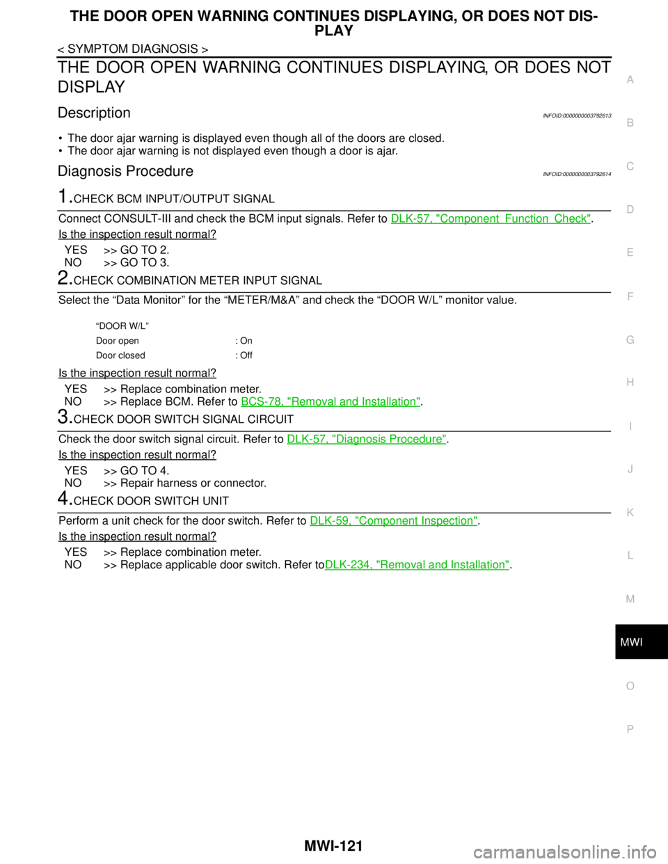
THE DOOR OPEN WARNING CONTINUES DISPLAYING, OR DOES NOT
DISPLAY
DescriptionINFOID:0000000003792613
The door ajar warning is displayed even though all of the doors are closed.
The door ajar warning is not displayed even though a door is ajar.
Diagnosis ProcedureINFOID:0000000003792614
1.CHECK BCM INPUT/OUTPUT SIGNAL
Connect CONSULT-III and check the BCM input signals. Refer to DLK-57, "
ComponentFunctionCheck".
Is the inspection result normal?
YES >> GO TO 2.
NO >> GO TO 3.
2.CHECK COMBINATION METER INPUT SIGNAL
Select the “Data Monitor” for the “METER/M&A” and check the “DOOR W/L” monitor value.
Is the inspection result normal?
YES >> Replace combination meter.
NO >> Replace BCM. Refer to BCS-78, "
Removal and Installation".
3.CHECK DOOR SWITCH SIGNAL CIRCUIT
Check the door switch signal circuit. Refer to DLK-57, "
Diagnosis Procedure".
Is the inspection result normal?
YES >> GO TO 4.
NO >> Repair harness or connector.
4.CHECK DOOR SWITCH UNIT
Perform a unit check for the door switch. Refer to DLK-59, "
Component Inspection".
Is the inspection result normal?
YES >> Replace combination meter.
NO >> Replace applicable door switch. Refer toDLK-234, "
Removal and Installation".
“DOOR W/L”
Door open : On
Door closed : Off
Page 3376 of 5121
MWI-122
< SYMPTOM DIAGNOSIS >
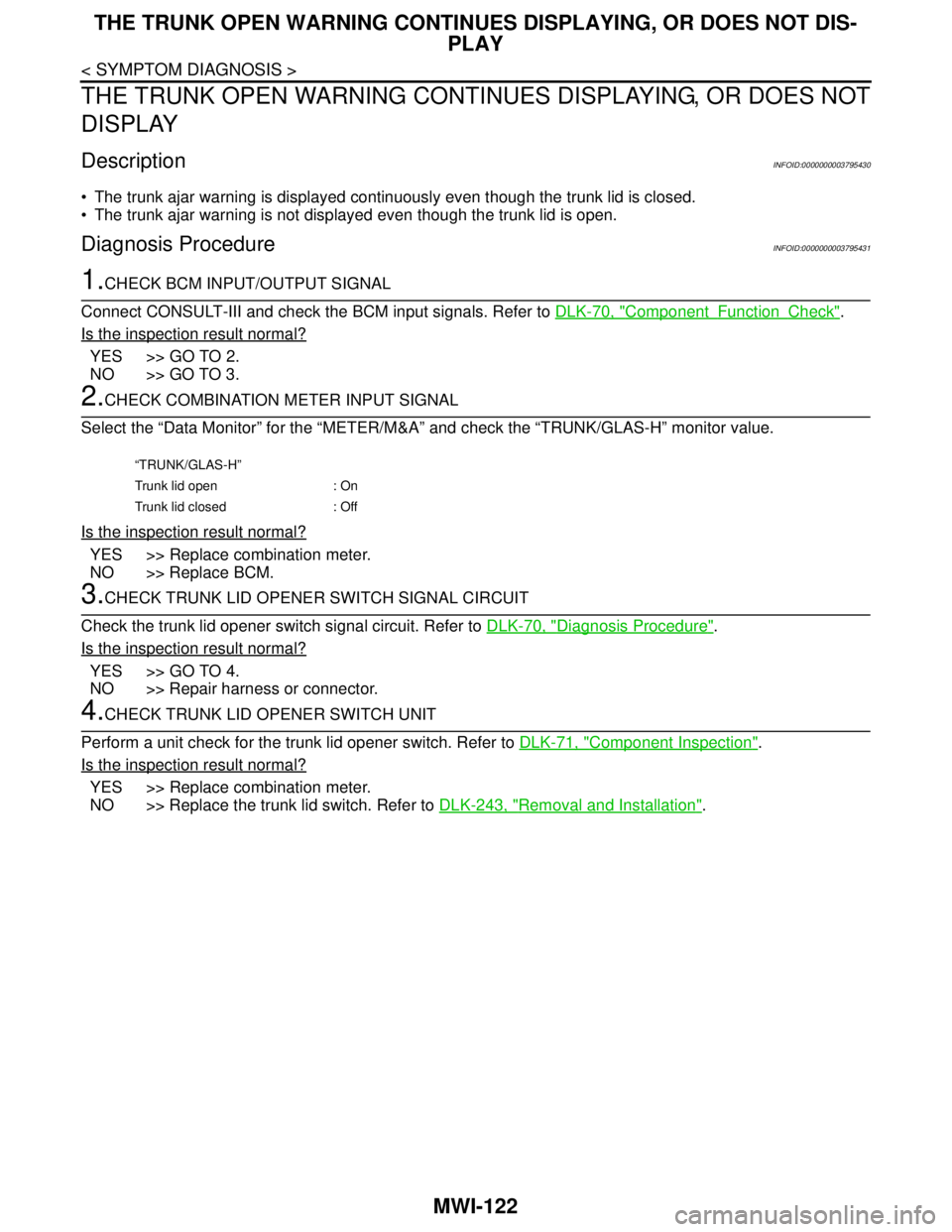
THE TRUNK OPEN WARNING CONTINUES DISPLAYING, OR DOES NOT DIS-
PLAY
THE TRUNK OPEN WARNING CONTINUES DISPLAYING, OR DOES NOT
DISPLAY
DescriptionINFOID:0000000003795430
The trunk ajar warning is displayed continuously even though the trunk lid is closed.
The trunk ajar warning is not displayed even though the trunk lid is open.
Diagnosis ProcedureINFOID:0000000003795431
1.CHECK BCM INPUT/OUTPUT SIGNAL
Connect CONSULT-III and check the BCM input signals. Refer to DLK-70, "
ComponentFunctionCheck".
Is the inspection result normal?
YES >> GO TO 2.
NO >> GO TO 3.
2.CHECK COMBINATION METER INPUT SIGNAL
Select the “Data Monitor” for the “METER/M&A” and check the “TRUNK/GLAS-H” monitor value.
Is the inspection result normal?
YES >> Replace combination meter.
NO >> Replace BCM.
3.CHECK TRUNK LID OPENER SWITCH SIGNAL CIRCUIT
Check the trunk lid opener switch signal circuit. Refer to DLK-70, "
Diagnosis Procedure".
Is the inspection result normal?
YES >> GO TO 4.
NO >> Repair harness or connector.
4.CHECK TRUNK LID OPENER SWITCH UNIT
Perform a unit check for the trunk lid opener switch. Refer to DLK-71, "
Component Inspection".
Is the inspection result normal?
YES >> Replace combination meter.
NO >> Replace the trunk lid switch. Refer to DLK-243, "
Removal and Installation".
“TRUNK/GLAS-H”
Trunk lid open : On
Trunk lid closed : Off
Page 3377 of 5121
MWI
THE AMBIENT TEMPERATURE DISPLAY IS INCORRECT
MWI-123
< SYMPTOM DIAGNOSIS >
C
D
E
F
G
H
I
J
K
L
MB A
O
P
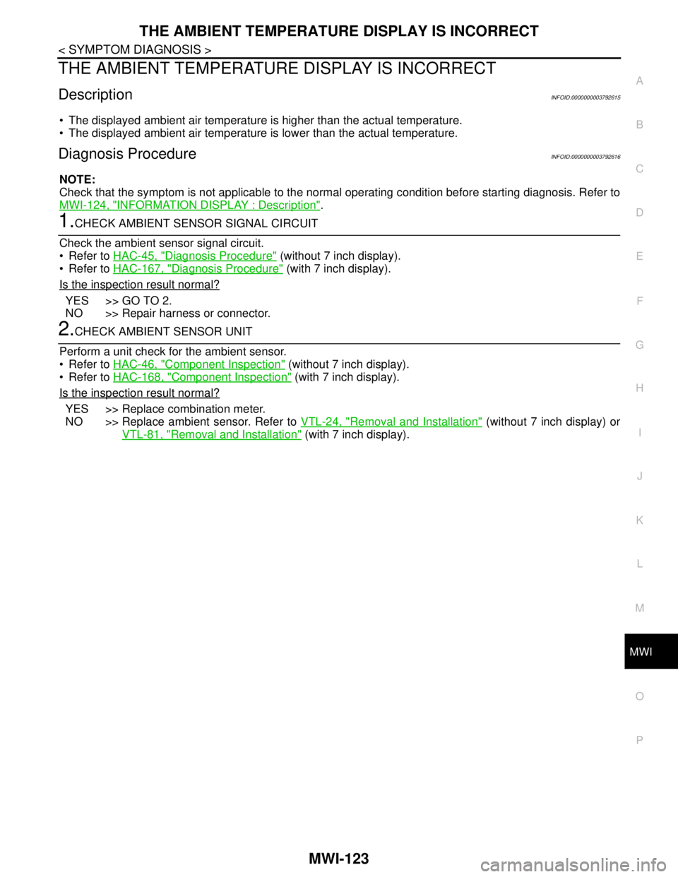
THE AMBIENT TEMPERATURE DISPLAY IS INCORRECT
DescriptionINFOID:0000000003792615
The displayed ambient air temperature is higher than the actual temperature.
The displayed ambient air temperature is lower than the actual temperature.
Diagnosis ProcedureINFOID:0000000003792616
NOTE:
Check that the symptom is not applicable to the normal operating condition before starting diagnosis. Refer to
MWI-124, "
INFORMATION DISPLAY : Description".
1.CHECK AMBIENT SENSOR SIGNAL CIRCUIT
Check the ambient sensor signal circuit.
Refer to HAC-45, "
Diagnosis Procedure" (without 7 inch display).
Refer to HAC-167, "
Diagnosis Procedure" (with 7 inch display).
Is the inspection result normal?
YES >> GO TO 2.
NO >> Repair harness or connector.
2.CHECK AMBIENT SENSOR UNIT
Perform a unit check for the ambient sensor.
Refer to HAC-46, "
Component Inspection" (without 7 inch display).
Refer to HAC-168, "
Component Inspection" (with 7 inch display).
Is the inspection result normal?
YES >> Replace combination meter.
NO >> Replace ambient sensor. Refer to VTL-24, "
Removal and Installation" (without 7 inch display) or
VTL-81, "
Removal and Installation" (with 7 inch display).
Page 3378 of 5121

MWI-124
< SYMPTOM DIAGNOSIS >
NORMAL OPERATING CONDITION
NORMAL OPERATING CONDITION
INFORMATION DISPLAY
INFORMATION DISPLAY : DescriptionINFOID:0000000003792618
AMBIENT AIR TEMPERATURE
The displayed ambient air temperature on the information display may differ from the actual temperature
because it is a corrected value calculated from the ambient sensor signal by the combination meter. Refer to
MWI-27, "
INFORMATION DISPLAY : System Description" for details on the correction process.
POSSIBLE DRIVING DISTANCE
The calculated possible driving distance may differ from the actual distance to empty if the refueling amount is
approximately 15 (3-3/10 Imp gal) or less. This is because the refuel control (moves the fuel gauge needle
quicker than normal judging that the driver is refueling the vehicle) is not performing.
Page 3379 of 5121

MWI
PRECAUTIONS
MWI-125
< PRECAUTION >
C
D
E
F
G
H
I
J
K
L
MB A
O
P
PRECAUTION
PRECAUTIONS
Precaution for Supplemental Restraint System (SRS) "AIR BAG" and "SEAT BELT
PRE-TENSIONER"
INFOID:0000000003940983
The Supplemental Restraint System such as “AIR BAG” and “SEAT BELT PRE-TENSIONER”, used along
with a front seat belt, helps to reduce the risk or severity of injury to the driver and front passenger for certain
types of collision. Information necessary to service the system safely is included in the “SRS AIRBAG” and
“SEAT BELT” of this Service Manual.
WARNING:
• To avoid rendering the SRS inoperative, which could increase the risk of personal injury or death in
the event of a collision which would result in air bag inflation, all maintenance must be performed by
an authorized NISSAN/INFINITI dealer.
Improper maintenance, including incorrect removal and installation of the SRS, can lead to personal
injury caused by unintentional activation of the system. For removal of Spiral Cable and Air Bag
Module, see the “SRS AIRBAG”.
Never use electrical test equipment on any circuit related to the SRS unless instructed to in this Ser-
vice Manual. SRS wiring harnesses can be identified by yellow and/or orange harnesses or harness
connectors.
Page 3380 of 5121
MWI-126
< ON-VEHICLE REPAIR >
COMBINATION METER
ON-VEHICLE REPAIR
COMBINATION METER
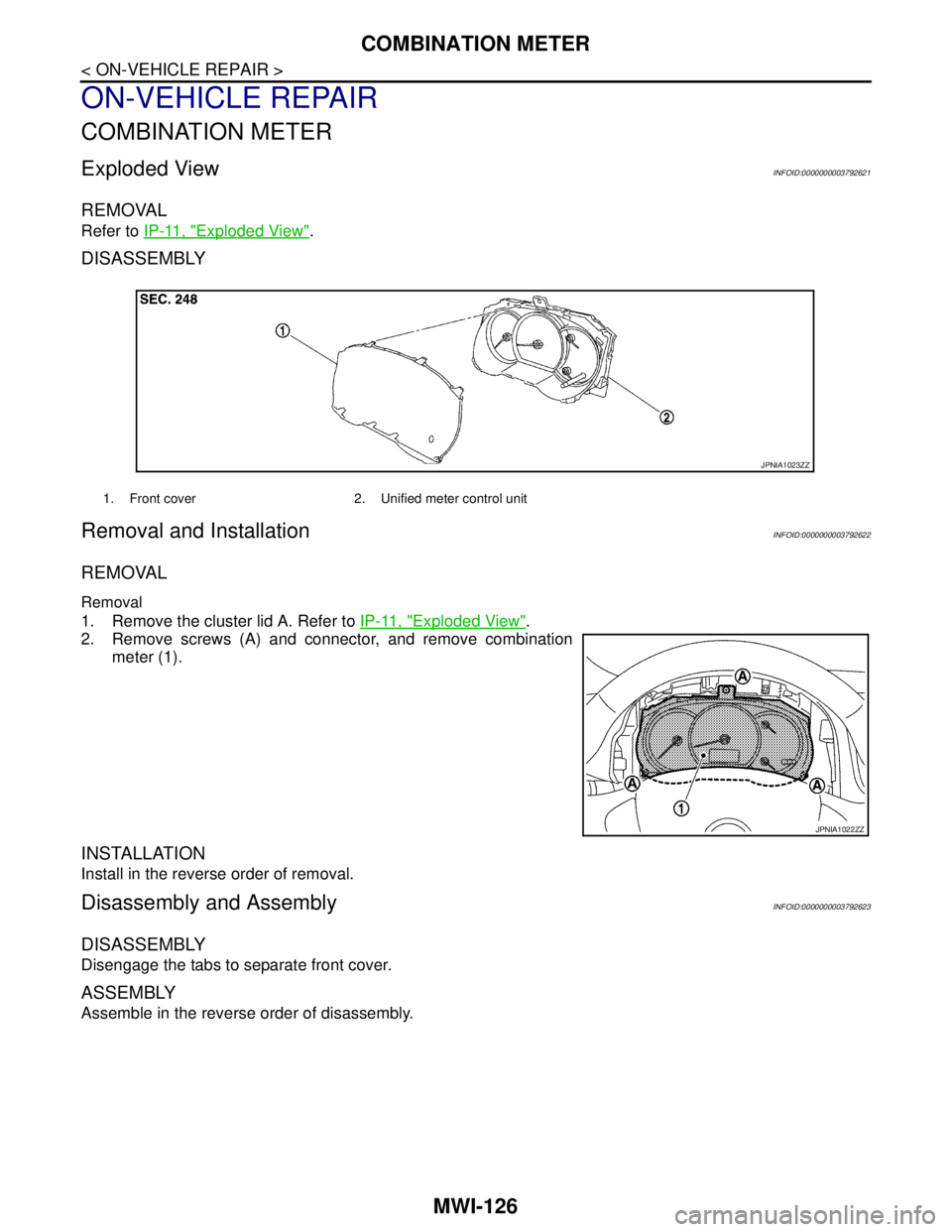
Exploded ViewINFOID:0000000003792621
REMOVAL
Refer to IP-11, "Exploded View".
DISASSEMBLY
Removal and InstallationINFOID:0000000003792622
REMOVAL
Removal
1. Remove the cluster lid A. Refer to IP-11, "Exploded View".
2. Remove screws (A) and connector, and remove combination
meter (1).
INSTALLATION
Install in the reverse order of removal.
Disassembly and AssemblyINFOID:0000000003792623
DISASSEMBLY
Disengage the tabs to separate front cover.
ASSEMBLY
Assemble in the reverse order of disassembly.
1. Front cover 2. Unified meter control unit
JPNIA1023ZZ
JPNIA1022ZZ