low oil pressure NISSAN TEANA 2008 Workshop Manual
[x] Cancel search | Manufacturer: NISSAN, Model Year: 2008, Model line: TEANA, Model: NISSAN TEANA 2008Pages: 5121, PDF Size: 69.03 MB
Page 2580 of 5121
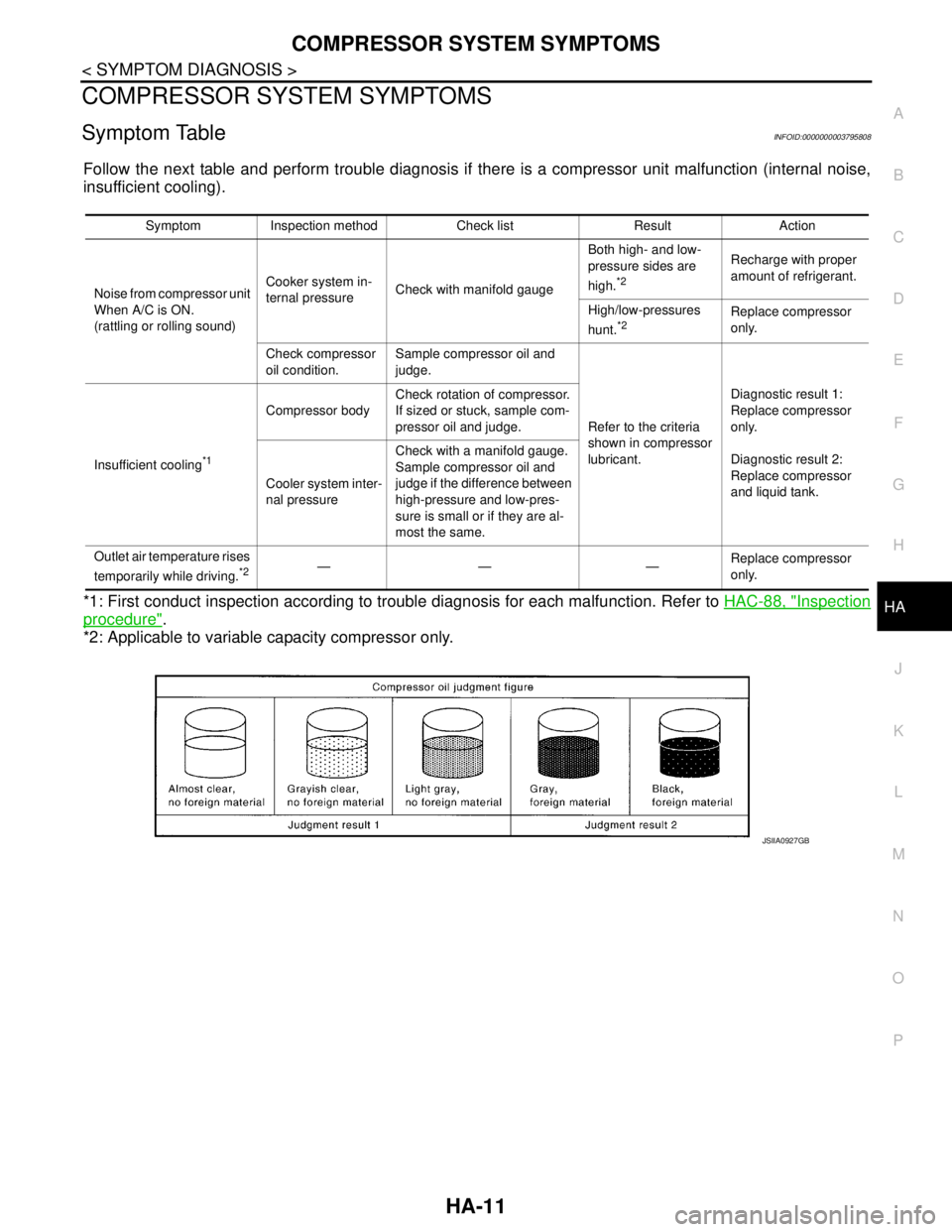
COMPRESSOR SYSTEM SYMPTOMS
HA-11
< SYMPTOM DIAGNOSIS >
C
D
E
F
G
H
J
K
L
MA
B
HA
N
O
P
COMPRESSOR SYSTEM SYMPTOMS
Symptom TableINFOID:0000000003795808
Follow the next table and perform trouble diagnosis if there is a compressor unit malfunction (internal noise,
insufficient cooling).
*1: First conduct inspection according to trouble diagnosis for each malfunction. Refer to HAC-88, "
Inspection
procedure".
*2: Applicable to variable capacity compressor only.
Symptom Inspection method Check list Result Action
Noise from compressor unit
When A/C is ON.
(rattling or rolling sound)Cooker system in-
ternal pressureCheck with manifold gaugeBoth high- and low-
pressure sides are
high.
*2
Recharge with proper
amount of refrigerant.
High/low-pressures
hunt.
*2Replace compressor
only.
Check compressor
oil condition.Sample compressor oil and
judge.
Refer to the criteria
shown in compressor
lubricant.Diagnostic result 1:
Replace compressor
only.
Diagnostic result 2:
Replace compressor
and liquid tank. Insufficient cooling
*1
Compressor bodyCheck rotation of compressor.
If sized or stuck, sample com-
pressor oil and judge.
Cooler system inter-
nal pressureCheck with a manifold gauge.
Sample compressor oil and
judge if the difference between
high-pressure and low-pres-
sure is small or if they are al-
most the same.
Outlet air temperature rises
temporarily while driving.
*2—— —Replace compressor
only.
JSIIA0927GB
Page 2584 of 5121
PRECAUTIONS
HA-15
< PRECAUTION >
C
D
E
F
G
H
J
K
L
MA
B
HA
N
O
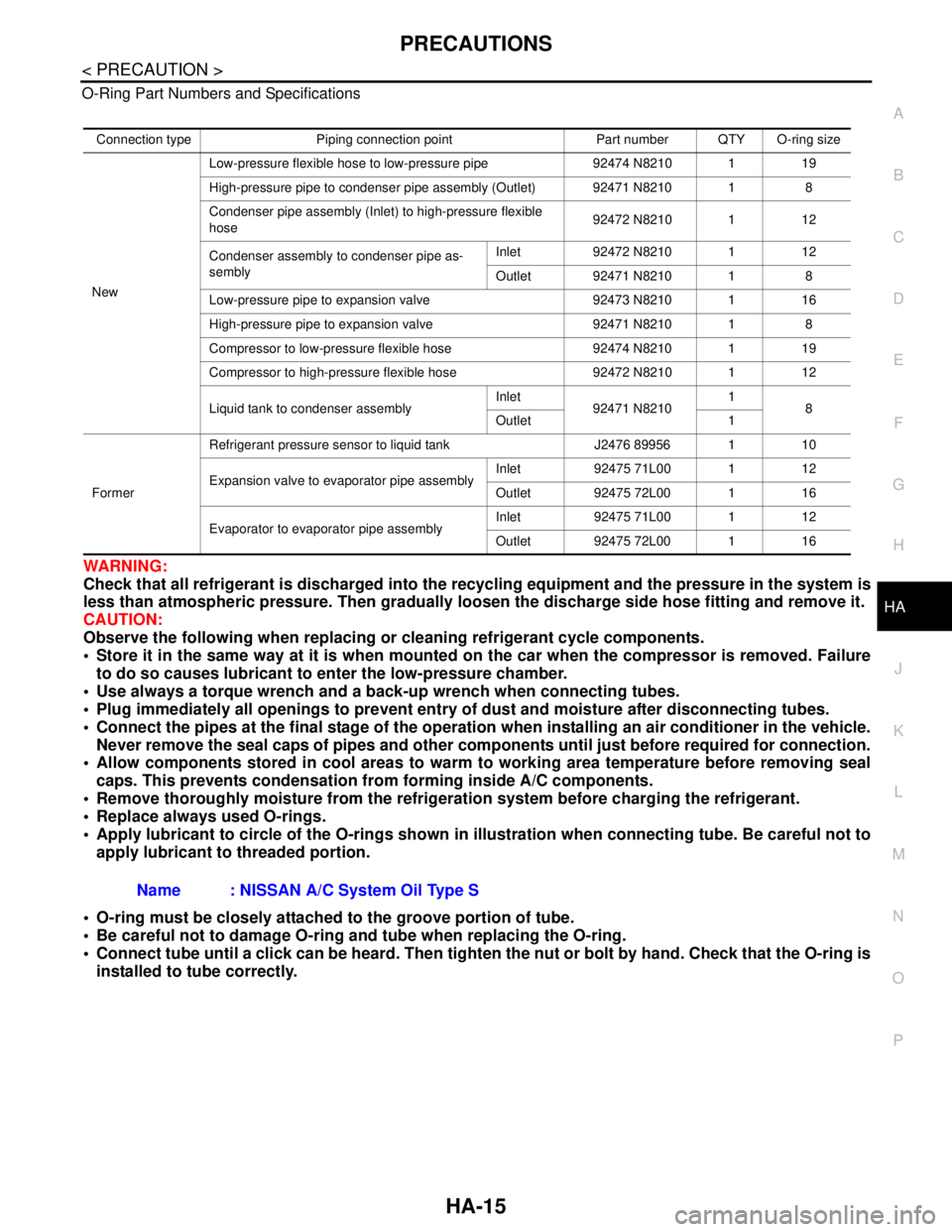
P O-Ring Part Numbers and Specifications
WARNING:
Check that all refrigerant is discharged into the recycling equipment and the pressure in the system is
less than atmospheric pressure. Then gradually loosen the discharge side hose fitting and remove it.
CAUTION:
Observe the following when replacing or cleaning refrigerant cycle components.
Store it in the same way at it is when mounted on the car when the compressor is removed. Failure
to do so causes lubricant to enter the low-pressure chamber.
Use always a torque wrench and a back-up wrench when connecting tubes.
Plug immediately all openings to prevent entry of dust and moisture after disconnecting tubes.
Connect the pipes at the final stage of the operation when installing an air conditioner in the vehicle.
Never remove the seal caps of pipes and other components until just before required for connection.
Allow components stored in cool areas to warm to working area temperature before removing seal
caps. This prevents condensation from forming inside A/C components.
Remove thoroughly moisture from the refrigeration system before charging the refrigerant.
Replace always used O-rings.
Apply lubricant to circle of the O-rings shown in illustration when connecting tube. Be careful not to
apply lubricant to threaded portion.
O-ring must be closely attached to the groove portion of tube.
Be careful not to damage O-ring and tube when replacing the O-ring.
Connect tube until a click can be heard. Then tighten the nut or bolt by hand. Check that the O-ring is
installed to tube correctly.
Connection type Piping connection point Part number QTY O-ring size
NewLow-pressure flexible hose to low-pressure pipe 92474 N8210 1 19
High-pressure pipe to condenser pipe assembly (Outlet) 92471 N8210 1 8
Condenser pipe assembly (Inlet) to high-pressure flexible
hose92472 N8210 1 12
Condenser assembly to condenser pipe as-
semblyInlet 92472 N8210 1 12
Outlet 92471 N8210 1 8
Low-pressure pipe to expansion valve 92473 N8210 1 16
High-pressure pipe to expansion valve 92471 N8210 1 8
Compressor to low-pressure flexible hose 92474 N8210 1 19
Compressor to high-pressure flexible hose 92472 N8210 1 12
Liquid tank to condenser assemblyInlet
92471 N82101
8
Outlet 1
FormerRefrigerant pressure sensor to liquid tank J2476 89956 1 10
Expansion valve to evaporator pipe assemblyInlet 92475 71L00 1 12
Outlet 92475 72L00 1 16
Evaporator to evaporator pipe assemblyInlet 92475 71L00 1 12
Outlet 92475 72L00 1 16
Name : NISSAN A/C System Oil Type S
Page 2591 of 5121
HA-22
< PREPARATION >
PREPARATION
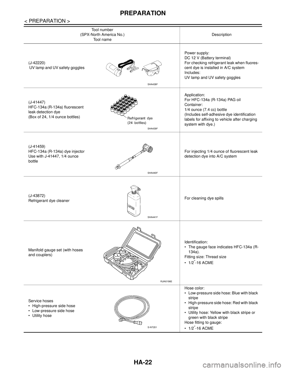
(J-42220)
UV lamp and UV safety gogglesPower supply:
DC 12 V (Battery terminal)
For checking refrigerant leak when fluores-
cent dye is installed in A/C system
Includes:
UV lamp and UV safety goggles
(J-41447)
HFC-134a (R-134a) fluorescent
leak detection dye
(Box of 24, 1/4 ounce bottles)Application:
For HFC-134a (R-134a) PAG oil
Container:
1/4 ounce (7.4 cc) bottle
(Includes self-adhesive dye identification
labels for affixing to vehicle after charging
system with dye.)
(J-41459)
HFC-134a (R-134a) dye injector
Use with J-41447, 1/4 ounce
bottleFor injecting 1/4 ounce of fluorescent leak
detection dye into A/C system
(J-43872)
Refrigerant dye cleanerFor cleaning dye spills
Manifold gauge set (with hoses
and couplers)Identification:
The gauge face indicates HFC-134a (R-
134a).
Fitting size: Thread size
1/2
″-16 ACME
Service hoses
High-pressure side hose
Low-pressure side hose
Utility hoseHose color:
Low-pressure side hose: Blue with black
stripe
High-pressure side hose: Red with black
stripe
Utility hose: Yellow with black stripe or
green with black stripe
Hose fitting to gauge:
1/2
″-16 ACME Tool number
(SPX-North America No.)
Tool nameDescription
SHA438F
SHA439F
SHA440F
SHA441F
RJIA0196E
S-NT201
Page 2592 of 5121
PREPARATION
HA-23
< PREPARATION >
C
D
E
F
G
H
J
K
L
MA
B
HA
N
O
PSealant or/and LubricantINFOID:0000000003795894
HFC-134a (R-134a) Service Tool and Equipment Never mix HFC-134a (R-134a) refrigerant and/or its specified lubricant with CFC-12 (R-12) refrigerant and/
or its lubricant.
Separate and non-interchangeable service equipment must be used for handling each type of refrigerant/
lubricant.
Refrigerant container fittings, service hose fittings and service equipment fittings (equipment which handles
refrigerant and/or lubricant) are different between CFC-12 (R-12) and HFC-134a (R-134a). This is to avoid
mixed use of the refrigerants/lubricant.
Never use adapters that convert one size fitting to another: refrigerant/lubricant contamination occurs and
compressor malfunction may result.
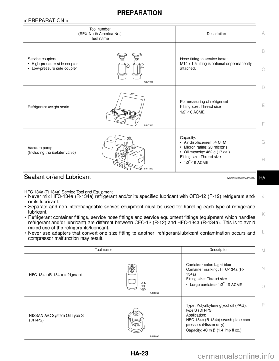
Service couplers
High-pressure side coupler
Low-pressure side couplerHose fitting to service hose:
M14 x 1.5 fitting is optional or permanently
attached.
Refrigerant weight scaleFor measuring of refrigerant
Fitting size: Thread size
1/2
″-16 ACME
Va c u u m p u m p
(Including the isolator valve)Capacity:
Air displacement: 4 CFM
Micron rating: 20 microns
Oil capacity: 482 g (17 oz.)
Fitting size: Thread size
1/2
″-16 ACME Tool number
(SPX-North America No.)
Tool nameDescription
S-NT202
S-NT200
S-NT203
Tool name Description
HFC-134a (R-134a) refrigerantContainer color: Light blue
Container marking: HFC-134a (R-
134a)
Fitting size: Thread size
Large container 1/2
″-16 ACME
NISSAN A/C System Oil Type S
(DH-PS)Type: Polyalkylene glycol oil (PAG),
type S (DH-PS)
Application:
HFC-134a (R-134a) swash plate com-
pressors (Nissan only)
Capacity: 40 m (1.4 Imp fl oz.)
S-NT196
S-NT197
Page 2594 of 5121
REFRIGERANT
HA-25
< ON-VEHICLE MAINTENANCE >
C
D
E
F
G
H
J
K
L
MA
B
HA
N
O
P
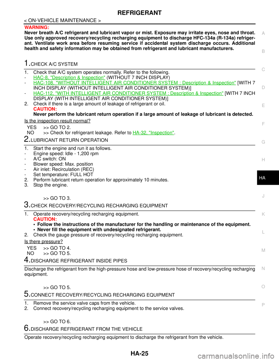
WARNING:
Never breath A/C refrigerant and lubricant vapor or mist. Exposure may irritate eyes, nose and throat.
Use only approved recovery/recycling recharging equipment to discharge HFC-134a (R-134a) refriger-
ant. Ventilate work area before resuming service if accidental system discharge occurs. Additional
health and safety information may be obtained from refrigerant and lubricant manufacturers.
1.CHECK A/C SYSTEM
1. Check that A/C system operates normally. Refer to the following.
-HAC-8, "
Description & Inspection" (WITHOUT 7 INCH DISPLAY)
-HAC-108, "
WITHOUT INTELLIGENT AIR CONDITIONER SYSTEM : Description & Inspection" [WITH 7
INCH DISPLAY (WITHOUT INTELLIGENT AIR CONDITIONER SYSTEM)]
-HAC-112, "
WITH INTELLIGENT AIR CONDITIONER SYSTEM : Description & Inspection" [WITH 7 INCH
DISPLAY (WITH INTELLIGENT AIR CONDITIONER SYSTEM)]
2. Check if there is a large amount of leakage of refrigerant or oil.
CAUTION:
Never perform the lubricant return operation if a large amount of leakage of lubricant is detected.
Is the inspection result normal?
YES >> GO TO 2.
NO >> Check for refrigerant leakage. Refer to HA-32, "
Inspection".
2.LUBRICANT RETURN OPERATION
1. Start the engine and run it as follows.
- Engine speed: Idle - 1,200 rpm
- A/C switch: ON
- Blower speed: Max. position
- Air inlet: Recirculation (REC)
- Set temperature: FULL HOT
2. Perform lubricant return operation for approximately 10 minutes.
3. Stop the engine.
>> GO TO 3.
3.CHECK RECOVERY/RECYCLING RECHARGING EQUIPMENT
1. Operate recovery/recycling recharging equipment.
CAUTION:
Follow the instructions of the manufacturer for the handling or maintenance of the equipment.
Never fill the equipment with undesignated refrigerant.
2. Check the gauge pressure of recovery/recycling recharging equipment.
Is there pressure?
YES >> GO TO 4.
NO >> GO TO 5.
4.DISCHARGE REFRIGERANT INSIDE PIPES
Discharge the refrigerant from the high-pressure hose and low-pressure hose of recovery/recycling recharging
equipment.
>> GO TO 5.
5.CONNECT RECOVERY/RECYCLING RECHARGING EQUIPMENT
1. Remove the service valve caps from the vehicle.
2. Connect recovery/recycling recharging equipment to the service valves.
>> GO TO 6.
6.DISCHARGE REFRIGERANT FROM THE VEHICLE
Operate recovery/recycling recharging equipment to discharge the refrigerant from the vehicle.
Page 2601 of 5121
HA-32
< ON-VEHICLE MAINTENANCE >
FLUORESCENT LEAK DETECTOR
FLUORESCENT LEAK DETECTOR
InspectionINFOID:0000000003795981
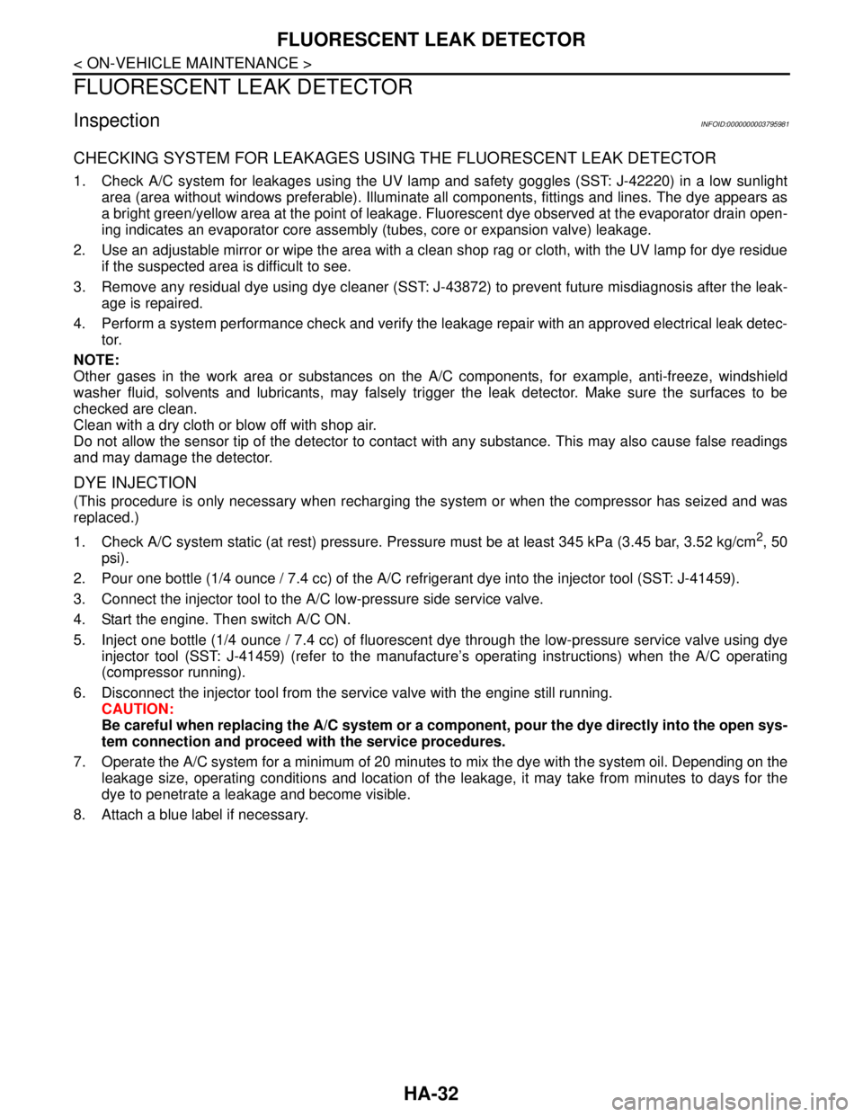
CHECKING SYSTEM FOR LEAKAGES USING THE FLUORESCENT LEAK DETECTOR
1. Check A/C system for leakages using the UV lamp and safety goggles (SST: J-42220) in a low sunlight
area (area without windows preferable). Illuminate all components, fittings and lines. The dye appears as
a bright green/yellow area at the point of leakage. Fluorescent dye observed at the evaporator drain open-
ing indicates an evaporator core assembly (tubes, core or expansion valve) leakage.
2. Use an adjustable mirror or wipe the area with a clean shop rag or cloth, with the UV lamp for dye residue
if the suspected area is difficult to see.
3. Remove any residual dye using dye cleaner (SST: J-43872) to prevent future misdiagnosis after the leak-
age is repaired.
4. Perform a system performance check and verify the leakage repair with an approved electrical leak detec-
tor.
NOTE:
Other gases in the work area or substances on the A/C components, for example, anti-freeze, windshield
washer fluid, solvents and lubricants, may falsely trigger the leak detector. Make sure the surfaces to be
checked are clean.
Clean with a dry cloth or blow off with shop air.
Do not allow the sensor tip of the detector to contact with any substance. This may also cause false readings
and may damage the detector.
DYE INJECTION
(This procedure is only necessary when recharging the system or when the compressor has seized and was
replaced.)
1. Check A/C system static (at rest) pressure. Pressure must be at least 345 kPa (3.45 bar, 3.52 kg/cm
2, 50
psi).
2. Pour one bottle (1/4 ounce / 7.4 cc) of the A/C refrigerant dye into the injector tool (SST: J-41459).
3. Connect the injector tool to the A/C low-pressure side service valve.
4. Start the engine. Then switch A/C ON.
5. Inject one bottle (1/4 ounce / 7.4 cc) of fluorescent dye through the low-pressure service valve using dye
injector tool (SST: J-41459) (refer to the manufacture’s operating instructions) when the A/C operating
(compressor running).
6. Disconnect the injector tool from the service valve with the engine still running.
CAUTION:
Be careful when replacing the A/C system or a component, pour the dye directly into the open sys-
tem connection and proceed with the service procedures.
7. Operate the A/C system for a minimum of 20 minutes to mix the dye with the system oil. Depending on the
leakage size, operating conditions and location of the leakage, it may take from minutes to days for the
dye to penetrate a leakage and become visible.
8. Attach a blue label if necessary.
Page 2608 of 5121
LOW-PRESSURE FLEXIBLE HOSE
HA-39
< ON-VEHICLE REPAIR >
C
D
E
F
G
H
J
K
L
MA
B
HA
N
O
P
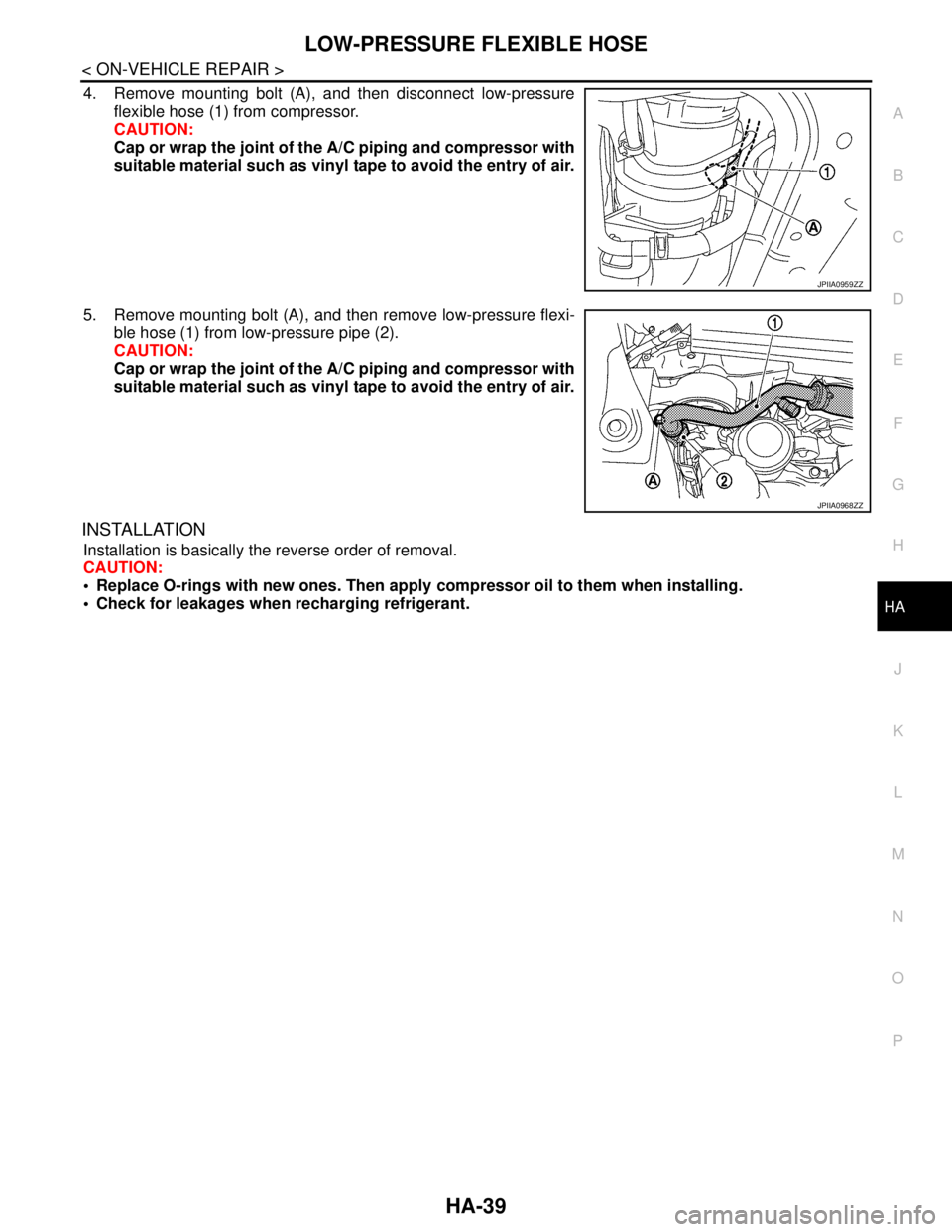
4. Remove mounting bolt (A), and then disconnect low-pressure
flexible hose (1) from compressor.
CAUTION:
Cap or wrap the joint of the A/C piping and compressor with
suitable material such as vinyl tape to avoid the entry of air.
5. Remove mounting bolt (A), and then remove low-pressure flexi-
ble hose (1) from low-pressure pipe (2).
CAUTION:
Cap or wrap the joint of the A/C piping and compressor with
suitable material such as vinyl tape to avoid the entry of air.
INSTALLATION
Installation is basically the reverse order of removal.
CAUTION:
Replace O-rings with new ones. Then apply compressor oil to them when installing.
Check for leakages when recharging refrigerant.
JPIIA0959ZZ
JPIIA0968ZZ
Page 2612 of 5121
LOW-PRESSURE PIPE
HA-43
< ON-VEHICLE REPAIR >
C
D
E
F
G
H
J
K
L
MA
B
HA
N
O
P
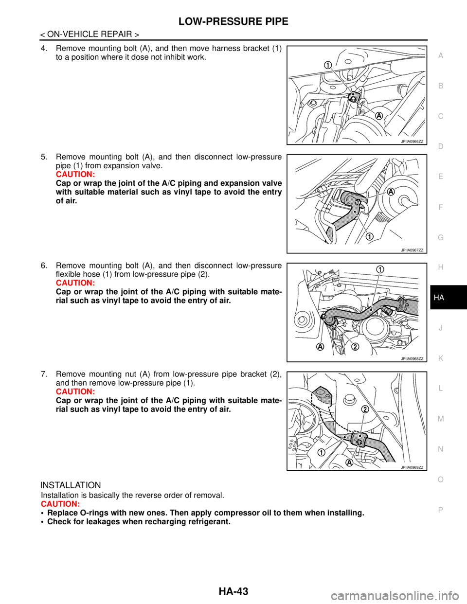
4. Remove mounting bolt (A), and then move harness bracket (1)
to a position where it dose not inhibit work.
5. Remove mounting bolt (A), and then disconnect low-pressure
pipe (1) from expansion valve.
CAUTION:
Cap or wrap the joint of the A/C piping and expansion valve
with suitable material such as vinyl tape to avoid the entry
of air.
6. Remove mounting bolt (A), and then disconnect low-pressure
flexible hose (1) from low-pressure pipe (2).
CAUTION:
Cap or wrap the joint of the A/C piping with suitable mate-
rial such as vinyl tape to avoid the entry of air.
7. Remove mounting nut (A) from low-pressure pipe bracket (2),
and then remove low-pressure pipe (1).
CAUTION:
Cap or wrap the joint of the A/C piping with suitable mate-
rial such as vinyl tape to avoid the entry of air.
INSTALLATION
Installation is basically the reverse order of removal.
CAUTION:
Replace O-rings with new ones. Then apply compressor oil to them when installing.
Check for leakages when recharging refrigerant.
JPIIA0966ZZ
JPIIA0967ZZ
JPIIA0968ZZ
JPIIA0969ZZ
Page 2619 of 5121
HA-50
< ON-VEHICLE REPAIR >
LIQUID TANK
LIQUID TANK
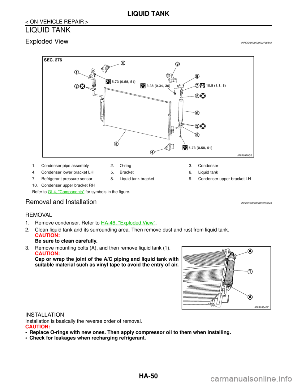
Exploded ViewINFOID:0000000003795848
Removal and InstallationINFOID:0000000003795849
REMOVAL
1. Remove condenser. Refer to HA-46, "Exploded View".
2. Clean liquid tank and its surrounding area. Then remove dust and rust from liquid tank.
CAUTION:
Be sure to clean carefully.
3. Remove mounting bolts (A), and then remove liquid tank (1).
CAUTION:
Cap or wrap the joint of the A/C piping and liquid tank with
suitable material such as vinyl tape to avoid the entry of air.
INSTALLATION
Installation is basically the reverse order of removal.
CAUTION:
Replace O-rings with new ones. Then apply compressor oil to them when installing.
Check for leakages when recharging refrigerant.
1. Condenser pipe assembly 2. O-ring 3. Condenser
4. Condenser lower bracket LH 5. Bracket 6. Liquid tank
7. Refrigerant pressure sensor 8. Liquid tank bracket 9. Condenser upper bracket LH
10. Condenser upper bracket RH
Refer to GI-4, "
Components" for symbols in the figure.
JPIIA0978GB
JPIIA0984ZZ
Page 2620 of 5121
REFRIGERANT PRESSURE SENSOR
HA-51
< ON-VEHICLE REPAIR >
C
D
E
F
G
H
J
K
L
MA
B
HA
N
O
P
REFRIGERANT PRESSURE SENSOR
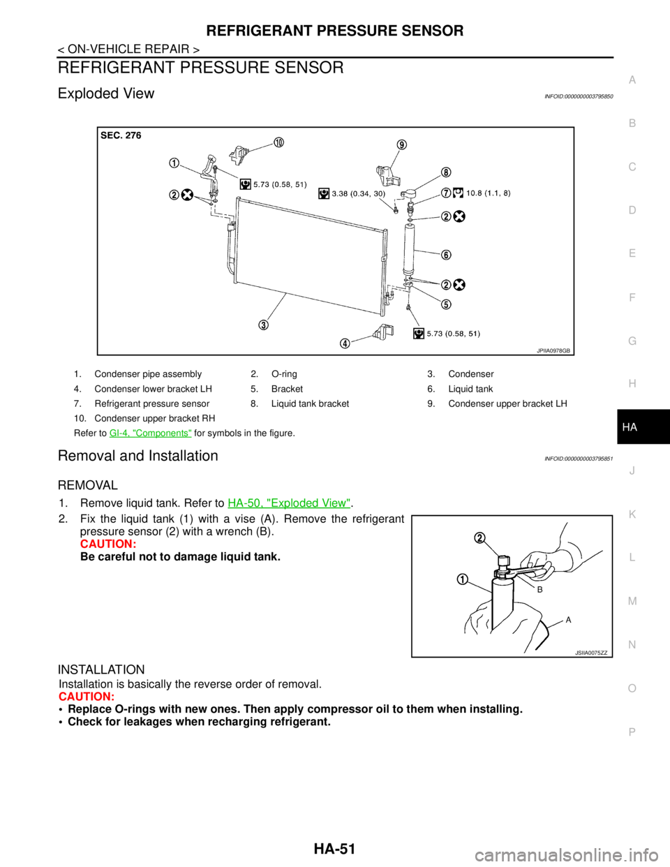
Exploded ViewINFOID:0000000003795850
Removal and InstallationINFOID:0000000003795851
REMOVAL
1. Remove liquid tank. Refer to HA-50, "Exploded View".
2. Fix the liquid tank (1) with a vise (A). Remove the refrigerant
pressure sensor (2) with a wrench (B).
CAUTION:
Be careful not to damage liquid tank.
INSTALLATION
Installation is basically the reverse order of removal.
CAUTION:
Replace O-rings with new ones. Then apply compressor oil to them when installing.
Check for leakages when recharging refrigerant.
1. Condenser pipe assembly 2. O-ring 3. Condenser
4. Condenser lower bracket LH 5. Bracket 6. Liquid tank
7. Refrigerant pressure sensor 8. Liquid tank bracket 9. Condenser upper bracket LH
10. Condenser upper bracket RH
Refer to GI-4, "
Components" for symbols in the figure.
JPIIA0978GB
JSIIA0075ZZ