transmission NISSAN TEANA 2008 Manual PDF
[x] Cancel search | Manufacturer: NISSAN, Model Year: 2008, Model line: TEANA, Model: NISSAN TEANA 2008Pages: 5121, PDF Size: 69.03 MB
Page 2766 of 5121

HAC-138
< FUNCTION DIAGNOSIS >[WITH 7 INCH DISPLAY]
AUTOMATIC AIR CONDITIONER SYSTEM
START: Initial compulsory signal is sent to each of the door motors.
ADDRESS: Data sent from the A/C auto amp. is selected according to data-based decisions made by the mode door
motor, the air mix door motors and the intake door motor.
If the addresses are identical, the opening angle data and error check signals are received by the door motor
LCUs. The LCUs then make the appropriate error decision. If the opening angle data has no error, door con-
trol begins.
If an error exists, the received data is rejected and the corrected data received. Finally, door control is based
upon the corrected opening angle data.
OPENING ANGLE:
Data that shows the indicated door opening angle of each door motor.
ERROR CHECK: In this procedure, transmitted and received data is checked for errors. Error data is then compiled. The error
check prevents corrupted data from being used by the mode door motor, the air mix door motors and the
intake door motor. Error data can be related to the following symptoms.
- Malfunction of electrical frequency
- Poor electrical connections
- Signal leakage from transmission lines
- Signal level fluctuation
STOP SIGNAL:
At the end of each transmission, a stop operation, in-operation, or internal malfunction message is delivered
to the A/C auto amp. This completes one data transmission and control cycle.
WITH INTELLIGENT AIR CONDITIONER SYSTEM : Component Part Location
INFOID:0000000003885178
ENGINE COMPARTMENT
JSIIA1132GB
Page 2783 of 5121

CAN COMMUNICATION SYSTEM
HAC-155
< FUNCTION DIAGNOSIS >[WITH 7 INCH DISPLAY]
C
D
E
F
G
H
J
K
L
MA
B
HAC
N
O
P
CAN COMMUNICATION SYSTEM
System DescriptionINFOID:0000000003884731
CAN (Controller Area Network) is a serial communication line for real time application. It is an on-vehicle mul-
tiplex communication line with high data communication speed and excellent error detection ability. Many elec-
tronic control units are equipped onto each vehicle, and each control unit shares information and links with
other control units during operation (not independent). In CAN communication, control units are connected
with 2 communication lines (CAN-H line, CAN-L line) allowing a high rate of information transmission with less
wiring. Each control unit transmits/receives data but selectively reads required data only. For details, refer to
LAN-22, "
CAN System Specification Chart".
Page 2792 of 5121

HAC-164
< COMPONENT DIAGNOSIS >[WITH 7 INCH DISPLAY]
U1000 CAN COMM CIRCUIT
COMPONENT DIAGNOSIS
U1000 CAN COMM CIRCUIT
DescriptionINFOID:0000000003884734
CAN (Controller Area Network) is a serial communication line for real time application. It is an on-vehicle mul-
tiplex communication line with high data communication speed and excellent error detection ability. Many elec-
tronic control units are equipped onto a vehicle, and each control unit shares information and links with other
control units during operation (not independent). In CAN communication, control units are connected with two
communication lines (CAN-H line, CAN-L line) allowing a high rate of information transmission with less wiring.
Each control unit transmits/receives data but selectively reads required data only.
CAN Communication Signal Chart. Refer to LAN-13, "
How to Use CAN Communication Signal Chart".
DTC LogicINFOID:0000000003884735
DTC DETECTION LOGIC
Diagnosis ProcedureINFOID:0000000003884736
1.CHECK WITH SELF-DIAGNOSIS FUNCTION OF CONSULT-III
1. Turn ignition switch ON and wait for 2 or more seconds.
2. Using CONSULT-III, perform “SELF-DIAGNOSIS RESULTS” of HVAC.
Is
“CAN COMM CIRCUIT” displayed?
YES >> Perform trouble diagnosis for the CAN communication system. Refer to LAN-14, "Trouble Diagno-
sis Flow Chart".
NO >> Perform the intermittent malfunction diagnosis. Refer to GI-35, "
Intermittent Incident".
DTCItems
(CONSULT-III screen terms)Diagnostic item is detected when... Possible cause
U1000 CAN COMM CIRCUITWhen A/C auto amp. is not transmitting
or receiving CAN communication signal
for 2 or more seconds.CAN communication system
Page 3025 of 5121
INT-48
< ON-VEHICLE REPAIR >
FLOOR TRIM
6. Remove instrument lower cover, instrument driver panel, instrument assist lower panel and instrument
side panel (LH/RH). Refer to IP-12, "
Removal and Installation".
7. Remove G-sensor. Refer to VTL-82, "
WITH INTELLIGENT AIR CONDITIONER SYSTEM : Removal and
Installation".
8. Remove diagnosis sensor unit. Refer to SR-22, "
Removal and Installation".
9. Remove dash side finisher (LH/RH), front kicking plate inner (LH/RH), center pillar lower garnish (LH/RH)
and body side welt (LH/RH). Refer to INT-39, "
Removal and Installation".
10. Remove side brake wire. Refer to BR-17, "
Removal and Installation".
11. Remove automatic transmission drive. Refer to FAX-16, "
Exploded View".
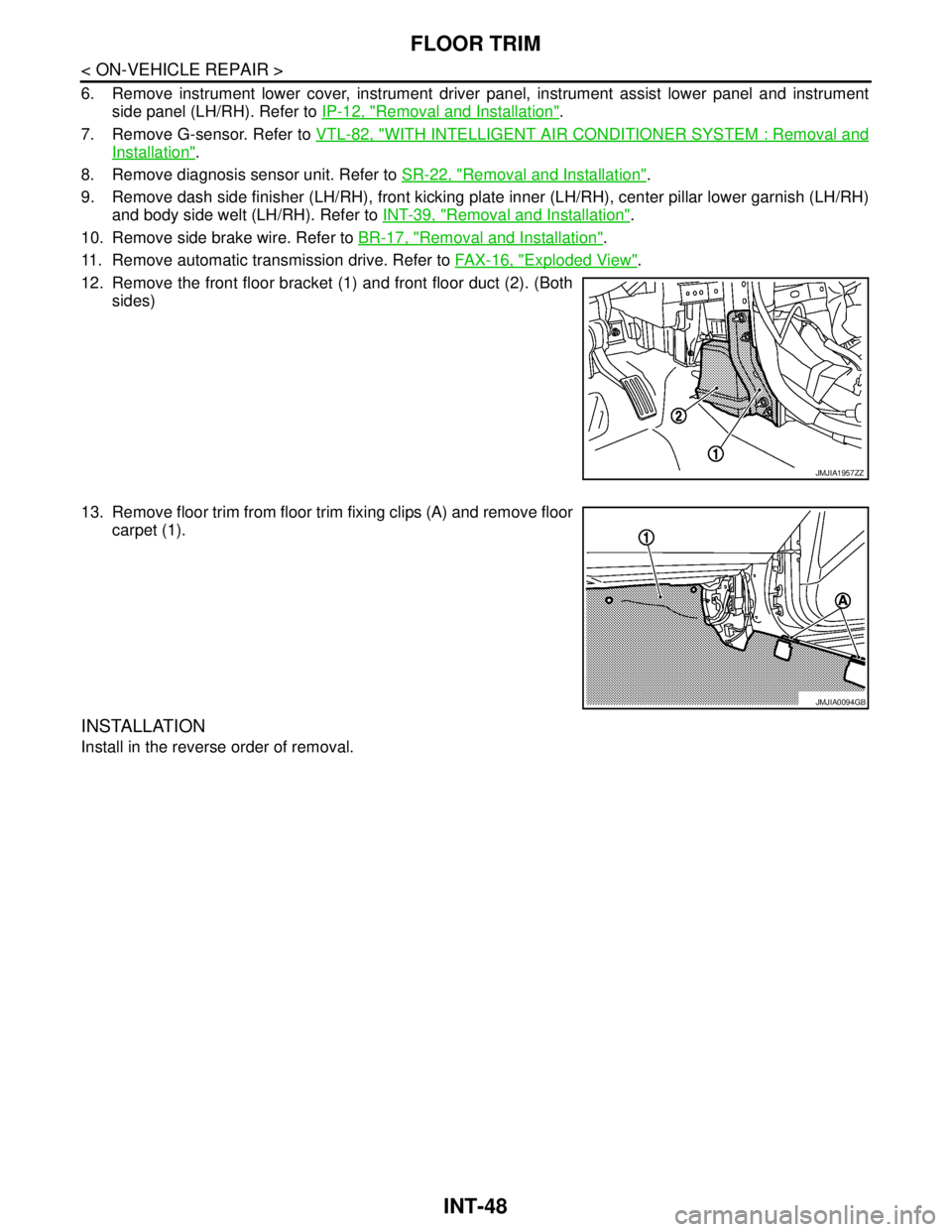
12. Remove the front floor bracket (1) and front floor duct (2). (Both
sides)
13. Remove floor trim from floor trim fixing clips (A) and remove floor
carpet (1).
INSTALLATION
Install in the reverse order of removal.
JMJIA1957ZZ
JMJIA0094GB
Page 3073 of 5121

LAN-6
< FUNCTION DIAGNOSIS >[CAN FUNDAMENTAL]
CAN COMMUNICATION SYSTEM
CAN Communication Control Circuit
INFOID:0000000003767667
*: These are the only control units wired with both ends of CAN communication system.
SKIB8713E
Component System description
CAN controller It controls CAN communication signal transmission and reception, error detection, etc.
Transceiver ICIt converts digital signal into CAN communication signal, and CAN communication signal into digital
signal.
Noise filter It eliminates noise of CAN communication signal.
Termination circuit
*
(Resistance of approx. 120 Ω)It produces potential difference.
Page 3076 of 5121

LAN
TROUBLE DIAGNOSIS
LAN-9
< FUNCTION DIAGNOSIS >[CAN FUNDAMENTAL]
C
D
E
F
G
H
I
J
K
L B A
O
P N Example: Data link connector branch line open circuit
NOTE:
When data link connector branch line is open, transmission and reception of CAN communication signals
are not affected. Therefore, no symptoms occur. However, be sure to repair malfunctioning circuit.
The model (all units on CAN communication system are Diag on CAN) cannot perform CAN diagnosis with
CONSULT-III if the following error occurs. The error is judged by the symptom.
EPS control unit Normal operation.
Combination meter Shift position indicator and OD OFF indicator turn OFF.
Warning lamps turn ON.
ABS actuator and electric unit (control unit) Normal operation.
TCM No impact on operation.
IPDM E/R Normal operation.Unit name Symptom
SKIB8739E
Unit name Symptom
ECM
Normal operation. BCM
EPS control unit
Combination meter
ABS actuator and electric unit (control unit)
TCM
IPDM E/R
Error Difference of symptom
Data link connector branch line open circuit Normal operation.
CAN-H, CAN-L harness short-circuitMost of the units which are connected to the CAN communication
system enter fail-safe mode or are deactivated.
Page 3079 of 5121

LAN-12
< FUNCTION DIAGNOSIS >[CAN FUNDAMENTAL]
TROUBLE DIAGNOSIS
Example: CAN DIAG SUPPORT MNTR indication
Without PAST
With PAST
MONITOR ITEM (ON-BOARD DIAGNOSIS)
NOTE:
For some models, CAN communication diagnosis result is received from the vehicle monitor.
JSMIA0015GB
Item PRSNT Description
Initial diagnosisOK Normal at present
NG Control unit error (Except for some control units)
Transmission diagnosisOK Normal at present
UNKWNUnable to transmit signals for 2 seconds or more.
Diagnosis not performed
Control unit name
(Reception diagnosis)OK Normal at present
UNKWNUnable to receive signals for 2 seconds or more.
Diagnosis not performed
No control unit for receiving signals. (No applicable optional parts)
Item PRSNT PAST Description
Transmission diagnosisOKOK Normal at present and in the past
1 – 39Normal at present, but unable to transmit signals for 2 seconds or more
in the past. (The number indicates the number of ignition switch cycles
from OFF to ON.)
UNKWN 0 Unable to transmit signals for 2 seconds or more at present.
Control unit name
(Reception diagnosis)OKOK Normal at present and in the past
1 – 39Normal at present, but unable to receive signals for 2 seconds or more
in the past. (The number indicates the number of ignition switch cycles
from OFF to ON.)
UNKWN 0 Unable to receive signals for 2 seconds or more at present.
––Diagnosis not performed.
No control unit for receiving signals. (No applicable optional parts)
Page 3080 of 5121

LAN
TROUBLE DIAGNOSIS
LAN-13
< FUNCTION DIAGNOSIS >[CAN FUNDAMENTAL]
C
D
E
F
G
H
I
J
K
L B A
O
P N
Example: Vehicle Display
How to Use CAN Communication Signal ChartINFOID:0000000003767675
The CAN communication signal chart lists the signals needed for trouble diagnosis. It is useful for detecting
the root cause by finding a signal related to the symptom, and by checking transmission and reception unit.
ItemResult indi-
catedError counter Description
CAN_COMM
(Initial diagnosis)OK 0 Normal at present
NG 1 – 50Control unit error
(The number indicates how many times diagnosis has been
run.)
CAN_CIRC_1
(Transmission diagnosis)OK 0 Normal at present
UNKWN 1 – 50Unable to transmit for 2 seconds or more at present.
(The number indicates how many times diagnosis has been
run.)
CAN_CIRC_2 – 9
(Reception diagnosis of each unit)OK 0 Normal at present
UNKWN 1 – 50Unable to transmit for 2 seconds or more at present.
(The number indicates how many times diagnosis has been
run.)
Diagnosis not performed.
No control unit for receiving signals. (No applicable optional
parts)
SKIB8715E
Page 3089 of 5121

LAN-22
< FUNCTION DIAGNOSIS >[CAN]
CAN COMMUNICATION SYSTEM
FUNCTION DIAGNOSIS
CAN COMMUNICATION SYSTEM
CAN System Specification ChartINFOID:0000000003767684
Determine CAN system type from the following specification chart.
NOTE:
Refer to LAN-14, "
Trouble Diagnosis Procedure" for how to use CAN system specification chart.
×: Applicable
VEHICLE EQUIPMENT IDENTIFICATION INFORMATION
NOTE:
Check CAN system type from the vehicle shape and equipment.
CAN Communication Signal ChartINFOID:0000000003767685
Refer to LAN-13, "How to Use CAN Communication Signal Chart" for how to use CAN communication signal
chart.
Body typeSedan
Axle2WD
Engine VQ25DE VQ35DE
TransmissionCVT
Brake control ABS VDC
Automatic drive positioner××
Color display×××
CAN system type 2469
Start CAN Diagnosis (CONSULT-III) 2469
JPMIA1011GB
Page 3195 of 5121
PERIODIC MAINTENANCE
MA-7
< ON-VEHICLE MAINTENANCE >
C
D
E
F
G
H
I
J
K
L
MB
MAN
OA
(5) Replace spark plug when the spark plug gap exceeds 1.4 mm (0.055 in) even if within specified periodic replacement
mileage.
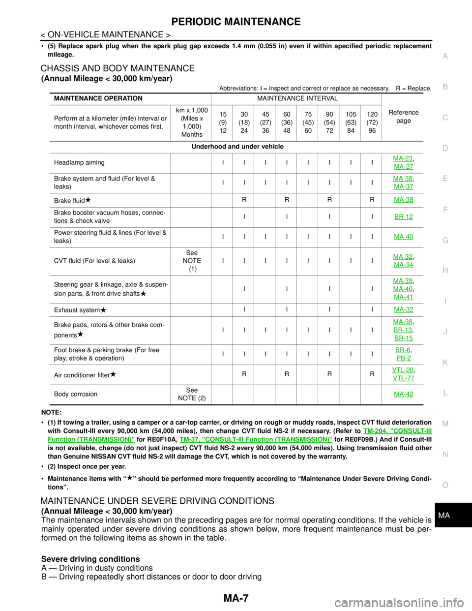
CHASSIS AND BODY MAINTENANCE
(Annual Mileage < 30,000 km/year)
Abbreviations: I = Inspect and correct or replace as necessary, R = Replace.
NOTE:
(1) If towing a trailer, using a camper or a car-top carrier, or driving on rough or muddy roads, inspect CVT fluid deterioration
with Consult-III every 90,000 km (54,000 miles), then change CVT fluid NS-2 if necessary. (Refer to TM-204, "
CONSULT-III
Function (TRANSMISSION)" for RE0F10A, TM-37, "CONSULT-III Function (TRANSMISSION)" for RE0F09B.) And if Consult-III
is not available, change (do not just inspect) CVT fluid NS-2 every 90,000 km (54,000 miles). Using transmission fluid other
than Genuine NISSAN CVT fluid NS-2 will damage the CVT, which is not covered by the warranty.
(2) Inspect once per year.
Maintenance items with “ ” should be performed more frequently according to “Maintenance Under Severe Driving Condi-
tions”.
MAINTENANCE UNDER SEVERE DRIVING CONDITIONS
(Annual Mileage < 30,000 km/year)
The maintenance intervals shown on the preceding pages are for normal operating conditions. If the vehicle is
mainly operated under severe driving conditions as shown below, more frequent maintenance must be per-
formed on the following items as shown in the table.
Severe driving conditions
A — Driving in dusty conditions
B — Driving repeatedly short distances or door to door driving
MAINTENANCE OPERATIONMAINTENANCE INTERVAL
Reference
page Perform at a kilometer (mile) interval or
month interval, whichever comes first.km x 1,000
(Miles x
1,000)
Months15
(9)
1230
(18)
2445
(27)
3660
(36)
4875
(45)
6090
(54)
72105
(63)
84120
(72)
96
Underhood and under vehicle
Headlamp aiming IIIIIIIIMA-23
,
MA-27
Brake system and fluid (For level &
leaks)IIIIIIIIMA-38,
MA-37
Brake fluidRRRRMA-38
Brake booster vacuum hoses, connec-
tions & check valveIIIIBR-12
Power steering fluid & lines (For level &
leaks)IIIIIIIIMA-40
CVT fluid (For level & leaks)See
NOTE
(1)IIIIIIIIMA-32,
MA-34
Steering gear & linkage, axle & suspen-
sion parts, & front drive shaftsIIIIMA-39,
MA-40
,
MA-41
Exhaust systemIIIIMA-32
Brake pads, rotors & other brake com-
ponentsIIIIIIIIMA-38,
BR-13
,
BR-15
Foot brake & parking brake (For free
play, stroke & operation)IIIIIIIIBR-6,
PB-2
Air conditioner filterRRRRVTL-20,
VTL-77
Body corrosionSee
NOTE (2)MA-42