transmission NISSAN TEANA 2008 Repair Manual
[x] Cancel search | Manufacturer: NISSAN, Model Year: 2008, Model line: TEANA, Model: NISSAN TEANA 2008Pages: 5121, PDF Size: 69.03 MB
Page 2536 of 5121
CONSULT-III/GST CHECKING SYSTEM
GI-43
< BASIC INSPECTION >
C
D
E
F
G
H
I
J
K
L
MB
GI
N
O
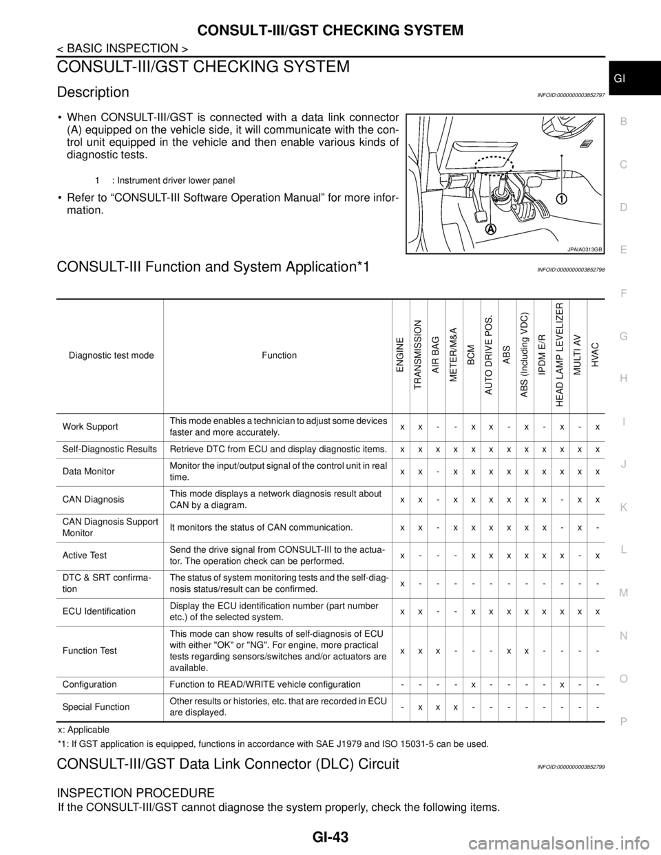
PCONSULT-III/GST CHECKING SYSTEM
DescriptionINFOID:0000000003852797
When CONSULT-III/GST is connected with a data link connector
(A) equipped on the vehicle side, it will communicate with the con-
trol unit equipped in the vehicle and then enable various kinds of
diagnostic tests.
Refer to “CONSULT-III Software Operation Manual” for more infor-
mation.
CONSULT-III Function and System Application*1INFOID:0000000003852798
x: Applicable
*1: If GST application is equipped, functions in accordance with SAE J1979 and ISO 15031-5 can be used.
CONSULT-III/GST Data Link Connector (DLC) CircuitINFOID:0000000003852799
INSPECTION PROCEDURE
If the CONSULT-III/GST cannot diagnose the system properly, check the following items.
1 : Instrument driver lower panel
JPAIA0313GB
Diagnostic test mode Function
ENGINE
TRANSMISSION
AIR BAG
METER/M&A
BCM
AUTO DRIVE POS.
ABS
ABS (Including VDC)
IPDM E/R
HEAD LAMP LEVELIZER
MULTI AV
HVAC
Work SupportThis mode enables a technician to adjust some devices
faster and more accurately.xx- -xx-x-x-x
Self-Diagnostic Results Retrieve DTC from ECU and display diagnostic items. x x x x x x x x x x x x
Data MonitorMonitor the input/output signal of the control unit in real
time.xx - xxxxxxxxx
CAN DiagnosisThis mode displays a network diagnosis result about
CAN by a diagram.xx - xxxxxx - xx
CAN Diagnosis Support
MonitorIt monitors the status of CAN communication. x x - x x x x x x - x -
Active TestSend the drive signal from CONSULT-III to the actua-
tor. The operation check can be performed.x - - - xxxxxx - x
DTC & SRT confirma-
tionThe status of system monitoring tests and the self-diag-
nosis status/result can be confirmed.x-----------
ECU IdentificationDisplay the ECU identification number (part number
etc.) of the selected system.xx - - xxxxxxxx
Function TestThis mode can show results of self-diagnosis of ECU
with either "OK" or "NG". For engine, more practical
tests regarding sensors/switches and/or actuators are
available.xxx---xx----
Configuration Function to READ/WRITE vehicle configuration - - - - x - - - - x - -
Special FunctionOther results or histories, etc. that are recorded in ECU
are displayed.-xxx--------
Page 2650 of 5121

HAC-22
< FUNCTION DIAGNOSIS >[WITHOUT 7 INCH DISPLAY]
AUTOMATIC AIR CONDITIONER SYSTEM
AIR CONDITIONER LAN CONTROL SYSTEM
The LAN (Local Area Network) system consists of the A/C auto amp., the mode door motor, the air mix door
motors and the intake door motor.
A configuration of these components is as shown in the figure below.
SYSTEM CONSTRUCTION
A small network exists between the A/C auto amp., the mode door motor, the air mix door motor and the intake
door motor. The A/C auto amp. and motors are connected by data transmission lines and motor power supply
lines. The LAN network is built through the ground circuits of each door motor.
Addresses, motor opening angle signals, motor stop signals and error checking messages are all transmitted
through the data transmission lines connecting the A/C auto amp. and each door motor.
The following functions are contained in LCUs built into the mode door motor, the air mix door motors and the
intake door motor.
Address
Motor opening angle signals
Data transmission
Motor stop and drive decision
Opening angle sensor (PBR function)
Comparison
JSIIA1186GB
JSIIA1129GB
Page 2651 of 5121

AUTOMATIC AIR CONDITIONER SYSTEM
HAC-23
< FUNCTION DIAGNOSIS >[WITHOUT 7 INCH DISPLAY]
C
D
E
F
G
H
J
K
L
MA
B
HAC
N
O
P
Decision (A/C auto amp. indicated value and motor opening angle comparison)
Operation
The A/C auto amp. receives data from each of the sensors. The A/C auto amp. sends mode door, the air mix
door and the intake door opening angle data to the mode door motor LCU, the air mix door motor LCUs and
the intake door motor LCU.
The mode door motor, the air mix door motors and the intake door motor read their respective signals accord-
ing to the address signal. Opening angle indication signals received from the A/C auto amp. and each of the
motor position sensors is compared by the LCUs in each door motor with the existing decision and opening
angles. Next, HOT/COLD, DEF/VENT, OPEN/SHUT or FRE/REC operation is selected. The new selection
data is returned to the A/C auto amp.
Transmission Data and Transmission Order
A/C auto amp. data is transmitted consecutively to each of the door motors following the form as shown in the
figure below.
START: Initial compulsory signal is sent to each of the door motors.
ADDRESS: Data sent from the A/C auto amp. is selected according to data-based decisions made by the mode door
motor, the air mix door motors and the intake door motor.
If the addresses are identical, the opening angle data and error check signals are received by the door motor
LCUs. The LCUs then make the appropriate error decision. If the opening angle data has no error, door con-
trol begins.
If an error exists, the received data is rejected and the corrected data received. Finally, door control is based
upon the corrected opening angle data.
OPENING ANGLE:
Data that shows the indicated door opening angle of each door motor.
ERROR CHECK: In this procedure, transmitted and received data is checked for errors. Error data is then compiled. The error
check prevents corrupted data from being used by the mode door motor, the air mix door motors and the
intake door motor. Error data can be related to the following symptoms.
- Malfunction of electrical frequency
- Poor electrical connections
- Signal leakage from transmission lines
- Signal level fluctuation
STOP SIGNAL:
JSIIA1130GB
JSIIA1131GB
Page 2652 of 5121

HAC-24
< FUNCTION DIAGNOSIS >[WITHOUT 7 INCH DISPLAY]
AUTOMATIC AIR CONDITIONER SYSTEM
At the end of each transmission, a stop operation, in-operation, or internal malfunction message is delivered
to the A/C auto amp. This completes one data transmission and control cycle.
Component Part LocationINFOID:0000000003846303
ENGINE COMPARTMENT
JSIIA1132GB
Page 2665 of 5121

CAN COMMUNICATION SYSTEM
HAC-37
< FUNCTION DIAGNOSIS >[WITHOUT 7 INCH DISPLAY]
C
D
E
F
G
H
J
K
L
MA
B
HAC
N
O
P
CAN COMMUNICATION SYSTEM
System DescriptionINFOID:0000000003846319
CAN (Controller Area Network) is a serial communication line for real time application. It is an on-vehicle mul-
tiplex communication line with high data communication speed and excellent error detection ability. Many elec-
tronic control units are equipped onto each vehicle, and each control unit shares information and links with
other control units during operation (not independent). In CAN communication, control units are connected
with 2 communication lines (CAN-H line, CAN-L line) allowing a high rate of information transmission with less
wiring. Each control unit transmits/receives data but selectively reads required data only. For details, refer to
LAN-22, "
CAN System Specification Chart".
Page 2670 of 5121

HAC-42
< COMPONENT DIAGNOSIS >[WITHOUT 7 INCH DISPLAY]
U1000 CAN COMM CIRCUIT
COMPONENT DIAGNOSIS
U1000 CAN COMM CIRCUIT
DescriptionINFOID:0000000003846322
CAN (Controller Area Network) is a serial communication line for real time application. It is an on-vehicle mul-
tiplex communication line with high data communication speed and excellent error detection ability. Many elec-
tronic control units are equipped onto a vehicle, and each control unit shares information and links with other
control units during operation (not independent). In CAN communication, control units are connected with two
communication lines (CAN-H line, CAN-L line) allowing a high rate of information transmission with less wiring.
Each control unit transmits/receives data but selectively reads required data only.
CAN Communication Signal Chart. Refer to LAN-13, "
How to Use CAN Communication Signal Chart".
DTC LogicINFOID:0000000003846323
DTC DETECTION LOGIC
Diagnosis ProcedureINFOID:0000000003846324
1.CHECK WITH SELF-DIAGNOSIS FUNCTION OF CONSULT-III
1. Turn ignition switch ON and wait for 2 or more seconds.
2. Using CONSULT-III, perform “SELF-DIAGNOSIS RESULTS” of HVAC.
Is
“CAN COMM CIRCUIT” displayed?
YES >> Perform trouble diagnosis for the CAN communication system. Refer to LAN-14, "Trouble Diagno-
sis Flow Chart".
NO >> Perform the intermittent malfunction diagnosis. Refer to GI-35, "
Intermittent Incident".
DTCItems
(CONSULT-III screen terms)Diagnostic item is detected when... Possible cause
U1000 CAN COMM CIRCUITWhen A/C auto amp. is not transmitting
or receiving CAN communication signal
for 2 or more seconds.CAN communication system
Page 2755 of 5121

AUTOMATIC AIR CONDITIONER SYSTEM
HAC-127
< FUNCTION DIAGNOSIS >[WITH 7 INCH DISPLAY]
C
D
E
F
G
H
J
K
L
MA
B
HAC
N
O
P
AIR CONDITIONER LAN CONTROL SYSTEM
The LAN (Local Area Network) system consists of the A/C auto amp., the mode door motor, the air mix door
motors and the intake door motor.
A configuration of these components is as shown in the figure below.
SYSTEM CONSTRUCTION
A small network exists between the A/C auto amp., the mode door motor, the air mix door motor and the intake
door motor. The A/C auto amp. and motors are connected by data transmission lines and motor power supply
lines. The LAN network is built through the ground circuits of each door motor.
Addresses, motor opening angle signals, motor stop signals and error checking messages are all transmitted
through the data transmission lines connecting the A/C auto amp. and each door motor.
The following functions are contained in LCUs built into the mode door motor, the air mix door motors and the
intake door motor.
Address
Motor opening angle signals
Data transmission
Motor stop and drive decision
Opening angle sensor (PBR function)
Comparison
JSIIA1189GB
JSIIA1129GB
Page 2756 of 5121

HAC-128
< FUNCTION DIAGNOSIS >[WITH 7 INCH DISPLAY]
AUTOMATIC AIR CONDITIONER SYSTEM
Decision (A/C auto amp. indicated value and motor opening angle comparison)
Operation
The A/C auto amp. receives data from each of the sensors. The A/C auto amp. sends mode door, the air mix
door and the intake door opening angle data to the mode door motor LCU, the air mix door motor LCUs and
the intake door motor LCU.
The mode door motor, the air mix door motors and the intake door motor read their respective signals accord-
ing to the address signal. Opening angle indication signals received from the A/C auto amp. and each of the
motor position sensors is compared by the LCUs in each door motor with the existing decision and opening
angles. Next, HOT/COLD, DEF/VENT, OPEN/SHUT or FRE/REC operation is selected. The new selection
data is returned to the A/C auto amp.
Transmission Data and Transmission Order
A/C auto amp. data is transmitted consecutively to each of the door motors following the form as shown in the
figure below.
START: Initial compulsory signal is sent to each of the door motors.
ADDRESS: Data sent from the A/C auto amp. is selected according to data-based decisions made by the mode door
motor, the air mix door motors and the intake door motor.
If the addresses are identical, the opening angle data and error check signals are received by the door motor
LCUs. The LCUs then make the appropriate error decision. If the opening angle data has no error, door con-
trol begins.
If an error exists, the received data is rejected and the corrected data received. Finally, door control is based
upon the corrected opening angle data.
OPENING ANGLE:
Data that shows the indicated door opening angle of each door motor.
ERROR CHECK: In this procedure, transmitted and received data is checked for errors. Error data is then compiled. The error
check prevents corrupted data from being used by the mode door motor, the air mix door motors and the
intake door motor. Error data can be related to the following symptoms.
- Malfunction of electrical frequency
- Poor electrical connections
- Signal leakage from transmission lines
- Signal level fluctuation
STOP SIGNAL:
JSIIA1130GB
JSIIA1131GB
Page 2757 of 5121

AUTOMATIC AIR CONDITIONER SYSTEM
HAC-129
< FUNCTION DIAGNOSIS >[WITH 7 INCH DISPLAY]
C
D
E
F
G
H
J
K
L
MA
B
HAC
N
O
P
At the end of each transmission, a stop operation, in-operation, or internal malfunction message is delivered
to the A/C auto amp. This completes one data transmission and control cycle.
WITHOUT INTELLIGENT AIR CONDITIONER SYSTEM : Component Part Location
INFOID:0000000003884706
ENGINE COMPARTMENT
JSIIA1132GB
Page 2765 of 5121

AUTOMATIC AIR CONDITIONER SYSTEM
HAC-137
< FUNCTION DIAGNOSIS >[WITH 7 INCH DISPLAY]
C
D
E
F
G
H
J
K
L
MA
B
HAC
N
O
P
A configuration of these components is as shown in the figure below.
SYSTEM CONSTRUCTION
A small network exists between the A/C auto amp., the mode door motor, the air mix door motor and the intake
door motor. The A/C auto amp. and motors are connected by data transmission lines and motor power supply
lines. The LAN network is built through the ground circuits of each door motor.
Addresses, motor opening angle signals, motor stop signals and error checking messages are all transmitted
through the data transmission lines connecting the A/C auto amp. and each door motor.
The following functions are contained in LCUs built into the mode door motor, the air mix door motors and the
intake door motor.
Address
Motor opening angle signals
Data transmission
Motor stop and drive decision
Opening angle sensor (PBR function)
Comparison
Decision (A/C auto amp. indicated value and motor opening angle comparison)
Operation
The A/C auto amp. receives data from each of the sensors. The A/C auto amp. sends mode door, the air mix
door and the intake door opening angle data to the mode door motor LCU, the air mix door motor LCUs and
the intake door motor LCU.
The mode door motor, the air mix door motors and the intake door motor read their respective signals accord-
ing to the address signal. Opening angle indication signals received from the A/C auto amp. and each of the
motor position sensors is compared by the LCUs in each door motor with the existing decision and opening
angles. Next, HOT/COLD, DEF/VENT, OPEN/SHUT or FRE/REC operation is selected. The new selection
data is returned to the A/C auto amp.
Transmission Data and Transmission Order
A/C auto amp. data is transmitted consecutively to each of the door motors following the form as shown in the
figure below.
JSIIA1129GB
JSIIA1130GB
JSIIA1131GB