NISSAN TEANA 2008 Manual Online
Manufacturer: NISSAN, Model Year: 2008, Model line: TEANA, Model: NISSAN TEANA 2008Pages: 5121, PDF Size: 69.03 MB
Page 81 of 5121

LIFTING MOTOR (REAR)
ADP-75
< COMPONENT DIAGNOSIS >
C
D
E
F
G
H
I
K
L
MA
B
ADP
N
O
P
Is the inspection result normal?
YES >> Replace driver seat control unit. Refer to ADP-136, "Removal and Installation".
NO >> Repair or replace harness.
Driver seat control unit
GroundContinuity
Connector Terminal
B4517
Not existed
8
Page 82 of 5121

ADP-76
< COMPONENT DIAGNOSIS >
SEAT MEMORY INDICATOR
SEAT MEMORY INDICATOR
DescriptionINFOID:0000000003759207
Memory indicators are equipped on the seat memory switch installed to the driver side door trim. The opera-
tion signal is inputted to the driver seat control unit when the memory switch is operated.
The status of automatic drive positioner system can be checked according to the illuminating/blinking status.
Component Function CheckINFOID:0000000003759208
1.CHECK FUNCTION
1. Select “MEMORY SW INDCTR” in “Active test” mode with CONSULT-III.
2. Check the memory indicator operation.
Is the operation of relevant parts normal?
YES >> Seat memory indicator function is OK.
NO >> Refer to ADP-76, "
DiagnosisProcedure".
Diagnosis ProcedureINFOID:0000000003759209
1.CHECK SEAT MEMORY INDICATOR OPERATION
Check seat memory indicator operation.
Which is the malfunctioning indicator?
All indicators are NG>>GO TO 2.
An indicator is NG>>GO TO 4.
2.CHECK FUSE
1. Turn ignition switch OFF.
2. Check that the blown fuse after repairing the affected circuit if a fuse is blown.
Is the fuse blown?
YES >> Replace the blown fuse after repairing the affected circuit if a fuse is blown.
NO >> GO TO 3.
3.CHECK SEAT MEMORY INDICATOR POWER SUPPLY
1. Disconnect seat memory switch connector.
2. Check voltage between seat memory switch harness connector and ground.
Is the inspection result normal?
YES >> GO TO 4.
NO >> Repair or replace harness.
4.CHECK SEAT MEMORY INDICATOR
Check seat memory indicator. Refer to ADP-77, "
Component Inspection".
Test item Description
MEMORY SW INDCTROFF
Memory switch indicatorOFF
ON-1 Indicator 1: ON
ON-2 Indicator 2: ON
Signal name Fuse No.
Battery power supply 10 (10A)
(+)
(–)Voltage (V)
(Approx.) Seat memory switch
Connector Terminal
D13 5 Ground Battery voltage
Page 83 of 5121

SEAT MEMORY INDICATOR
ADP-77
< COMPONENT DIAGNOSIS >
C
D
E
F
G
H
I
K
L
MA
B
ADP
N
O
P
Is the inspection result normal?
YES >> GO TO 5.
NO >> Replace seat memory switch. Refer to ADP-137, "
Removal and Installation".
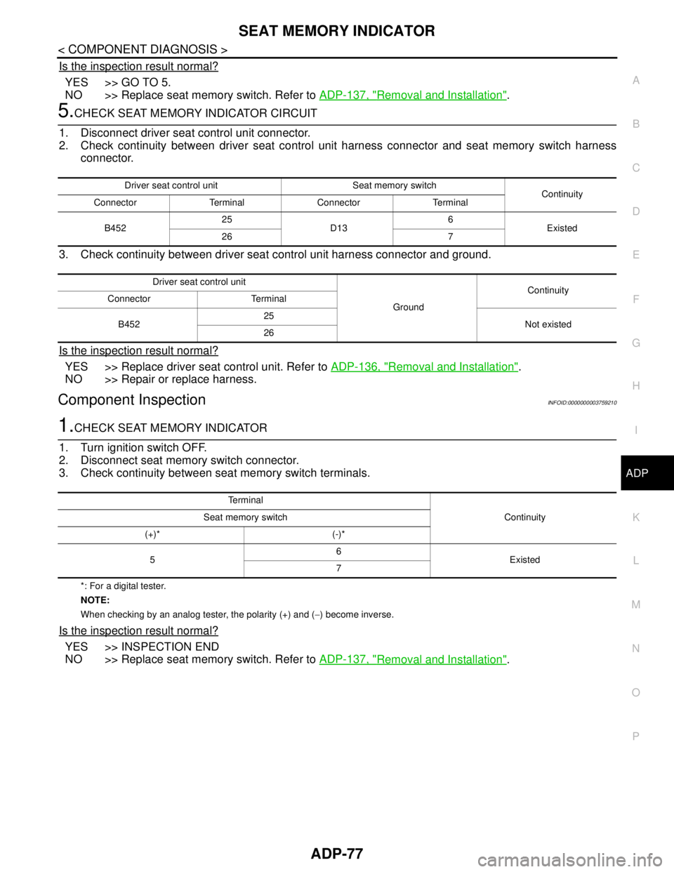
5.CHECK SEAT MEMORY INDICATOR CIRCUIT
1. Disconnect driver seat control unit connector.
2. Check continuity between driver seat control unit harness connector and seat memory switch harness
connector.
3. Check continuity between driver seat control unit harness connector and ground.
Is the inspection result normal?
YES >> Replace driver seat control unit. Refer to ADP-136, "Removal and Installation".
NO >> Repair or replace harness.
Component InspectionINFOID:0000000003759210
1.CHECK SEAT MEMORY INDICATOR
1. Turn ignition switch OFF.
2. Disconnect seat memory switch connector.
3. Check continuity between seat memory switch terminals.
*: For a digital tester.
NOTE:
When checking by an analog tester, the polarity (+) and (−) become inverse.
Is the inspection result normal?
YES >> INSPECTION END
NO >> Replace seat memory switch. Refer to ADP-137, "
Removal and Installation".
Driver seat control unit Seat memory switch
Continuity
Connector Terminal Connector Terminal
B45225
D136
Existed
26 7
Driver seat control unit
GroundContinuity
Connector Terminal
B45225
Not existed
26
Te r m i n a l
Continuity Seat memory switch
(+)* (-)*
56
Existed
7
Page 84 of 5121

ADP-78
< COMPONENT DIAGNOSIS >
BCM (BODY CONTROL MODULE)
BCM (BODY CONTROL MODULE)
Reference ValueINFOID:0000000003940046
VALUES ON THE DIAGNOSIS TOOL
CONSULT-III MONITOR ITEM
Monitor Item Condition Value/Status
FR WIPER HIOther than front wiper switch HI Off
Front wiper switch HI On
FR WIPER LOWOther than front wiper switch LO Off
Front wiper switch LO On
FR WASHER SWFront washer switch OFF Off
Front washer switch ON On
FR WIPER INTOther than front wiper switch INT Off
Front wiper switch INT On
FR WIPER STOPFront wiper is not in STOP position Off
Front wiper is in STOP position On
INT VOLUME Wiper intermittent dial is in a dial position 1 - 7 Wiper intermittent dial position
TURN SIGNAL ROther than turn signal switch RH Off
Turn signal switch RH On
TURN SIGNAL LOther than turn signal switch LH Off
Turn signal switch LH On
TAIL LAMP SWOther than lighting switch 1ST and 2ND Off
Lighting switch 1ST or 2ND On
HI BEAM SWOther than lighting switch HI Off
Lighting switch HI On
HEAD LAMP SW 1Other than lighting switch 2ND Off
Lighting switch 2ND On
HEAD LAMP SW 2Other than lighting switch 2ND Off
Lighting switch 2ND On
PASSING SWOther than lighting switch PASS Off
Lighting switch PASS On
AUTO LIGHT SWOther than lighting switch AUTO Off
Lighting switch AUTO On
FR FOG SWFront fog lamp switch OFF Off
Front fog lamp switch ON On
RR FOG SWRear fog lamp switch OFF Off
Rear fog lamp switch ON On
DOOR SW-DRDriver door closed Off
Driver door opened On
DOOR SW-ASPassenger door closed Off
Passenger door opened On
DOOR SW-RRRear RH door closed Off
Rear RH door opened On
DOOR SW-RLRear LH door closed Off
Rear LH door opened On
Page 85 of 5121

BCM (BODY CONTROL MODULE)
ADP-79
< COMPONENT DIAGNOSIS >
C
D
E
F
G
H
I
K
L
MA
B
ADP
N
O
P
DOOR SW-BKNOTE:
The item is indicated, but not monitored. Off
CDL LOCK SWOther than power door lock switch LOCK Off
Power door lock switch LOCK On
CDL UNLOCK SWOther than power door lock switch UNLOCK Off
Power door lock switch UNLOCK On
KEY CYL LK-SWNOTE:
The item is indicated, but not monitored. Off
KEY CYL UN-SWNOTE:
The item is indicated, but not monitored. Off
KEY CYL SW-TRNOTE:
The item is indicated, but not monitored. Off
HAZARD SWHazard switch is OFF Off
Hazard switch is ON On
REAR DEF SW
NOTE:
At model with BOSE au-
dio system this item is in-
dicated, but is not
monitored.Rear window defogger switch is OFF Off
Rear window defogger switch is ON On
TR CANCEL SWNOTE:
The item is indicated, but not monitored. Off
TR/BD OPEN SWTrunk lid opener switch OFF Off
While the trunk lid opener switch is turned ON On
TRNK/HAT MNTRTrunk lid closed Off
Trunk lid opened On
RKE-LOCKLOCK button of the key is not pressed Off
LOCK button of the key is pressed On
RKE-UNLOCKUNLOCK button of the key is not pressed Off
UNLOCK button of the key is pressed On
RKE-TR/BDTRUNK OPEN button of the key is not pressed Off
TRUNK OPEN button of the key is pressed On
RKE-PANICNOTE:
The item is indicated, but not monitored. Off
RKE-P/W OPENNOTE:
The item is indicated, but not monitored. Off
RKE-MODE CHGLOCK/UNLOCK button of the key is not pressed and held simulta-
neouslyOff
LOCK/UNLOCK button of the key is pressed and held simulta-
neouslyOn
OPTICAL SENSORBright outside of the vehicle Close to 5 V
Dark outside of the vehicle Close to 0 V
REQ SW -DRDriver door request switch is not pressed Off
Driver door request switch is pressed On
REQ SW -ASPassenger door request switch is not pressed Off
Passenger door request switch is pressed On
REQ SW -RRNOTE:
The item is indicated, but not monitored. Off Monitor Item Condition Value/Status
Page 86 of 5121

ADP-80
< COMPONENT DIAGNOSIS >
BCM (BODY CONTROL MODULE)
REQ SW -RRNOTE:
The item is indicated, but not monitored. Off
REQ SW -BD/TRTrunk lid opener request switch is not pressed Off
Trunk lid opener request switch is pressed On
PUSH SWPush-button ignition switch (push switch) is not pressed Off
Push-button ignition switch (push switch) is pressed On
IGN RLY2 -F/BIgnition switch in OFF or ACC position Off
Ignition switch in ON position On
CLUCH SWNOTE:
The item is indicated, but not monitored. Off
BRAKE SW 1The brake pedal is not depressed On
The brake pedal is depressed Off
DETE/CANCL SWSelector lever in P position Off
Selector lever in any position other than P On
SFT PN/N SWSelector lever in any position other than P and N Off
Selector lever in P or N position On
S/L -LOCKSteering is locked Off
Steering is unlocked On
S/L -UNLOCKSteering is unlocked Off
Steering is locked On
S/L RELAY-F/BIgnition switch in OFF or ACC position Off
Ignition switch in ON position On
UNLK SEN -DRDriver door is unlocked Off
Driver door is locked On
PUSH SW -IPDMPush-button ignition switch (push-switch) is not pressed Off
Push-button ignition switch (push-switch) is pressed On
IGN RLY1 -F/BIgnition switch in OFF or ACC position Off
Ignition switch in ON position On
DETE SW -IPDMSelector lever in P position Off
Selector lever in any position other than P On
SFT PN -IPDMSelector lever in any position other than P and N Off
Selector lever in P or N position On
SFT P -METSelector lever in any position other than P Off
Selector lever in P position On
SFT N -METSelector lever in any position other than N Off
Selector lever in N position On
ENGINE STATEEngine stopped Stop
While the engine stalls Stall
At engine cranking Crank
Engine running Run
S/L LOCK-IPDMSteering is locked Off
Steering is unlocked On
S/L UNLK-IPDMSteering is unlocked Off
Steering is locked On Monitor Item Condition Value/Status
Page 87 of 5121

BCM (BODY CONTROL MODULE)
ADP-81
< COMPONENT DIAGNOSIS >
C
D
E
F
G
H
I
K
L
MA
B
ADP
N
O
P
S/L RELAY-REQIgnition switch in OFF or ACC position Off
Ignition switch in ON position On
VEH SPEED 1 While driving Equivalent to speedometer reading
VEH SPEED 2 While driving Equivalent to speedometer reading
DOOR STAT-DRDriver door is locked LOCK
Wait with selective UNLOCK operation (5 seconds) READY
Driver door is unlocked UNLOCK
DOOR STAT-ASPassenger door is locked LOCK
Wait with selective UNLOCK operation (5 seconds) READY
Passenger door is unlocked UNLOCK
ID OK FLAGIgnition switch in ACC or ON position Reset
Ignition switch in OFF position Set
PRMT ENG STRTThe engine start is prohibited Reset
The engine start is permitted Set
PRMT RKE STRTNOTE:
The item is indicated, but not monitored. Reset
KEY SW -SLOTThe key is not inserted into key slot Off
The key is inserted into key slot On
RKE OPE COUN1 During the operation of the key Operation frequency of the key
RKE OPE COUN2NOTE:
The item is indicated, but not monitored. —
CONFRM ID ALLThe key ID that the key slot receives does not accord with any key
ID registered to BCM.Ye t
The key ID that the key slot receives accords with any key ID regis-
tered to BCM.Done
CONFIRM ID4The key ID that the key slot receives does not accord with the fourth
key ID registered to BCM.Ye t
The key ID that the key slot receives accords with the fourth key ID
registered to BCM.Done
CONFIRM ID3The key ID that the key slot receives does not accord with the third
key ID registered to BCM.Ye t
The key ID that the key slot receives accords with the third key ID
registered to BCM.Done
CONFIRM ID2The key ID that the key slot receives does not accord with the sec-
ond key ID registered to BCM.Ye t
The key ID that the key slot receives accords with the second key
ID registered to BCM.Done
CONFIRM ID1The key ID that the key slot receives does not accord with the first
key ID registered to BCM.Ye t
The key ID that the key slot receives accords with the first key ID
registered to BCM.Done
TP 4The ID of fourth key is not registered to BCM Yet
The ID of fourth key is registered to BCM Done
TP 3The ID of third key is not registered to BCM Yet
The ID of third key is registered to BCM Done
TP 2The ID of second key is not registered to BCM Yet
The ID of second key is registered to BCM Done Monitor Item Condition Value/Status
Page 88 of 5121

ADP-82
< COMPONENT DIAGNOSIS >
BCM (BODY CONTROL MODULE)
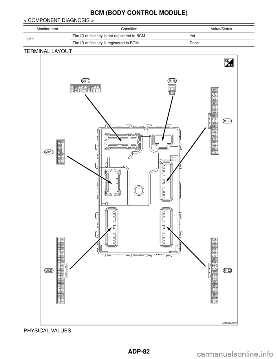
TERMINAL LAYOUT
PHYSICAL VALUES
TP 1The ID of first key is not registered to BCM Yet
The ID of first key is registered to BCM Done Monitor Item Condition Value/Status
JPMIA0062ZZ
Page 89 of 5121

BCM (BODY CONTROL MODULE)
ADP-83
< COMPONENT DIAGNOSIS >
C
D
E
F
G
H
I
K
L
MA
B
ADP
N
O
P
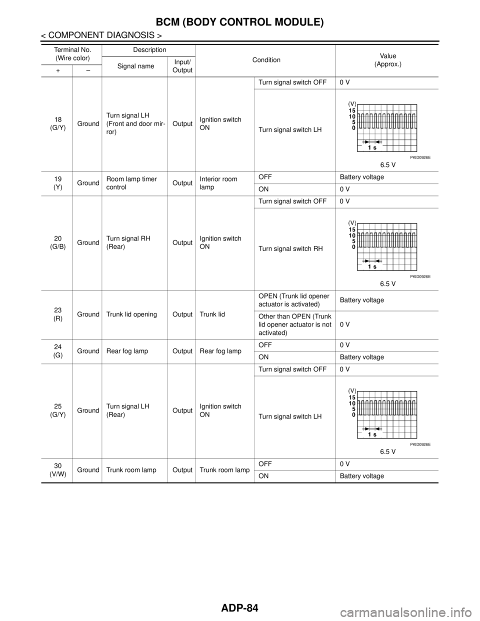
Te r m i n a l N o .
(Wire color)Description
ConditionVa l u e
(Approx.)
Signal nameInput/
Output +–
1
(W/B)GroundBattery power sup-
plyInput Ignition switch OFF Battery voltage
2
(R/Y)GroundP/W power supply
(BAT)Output Ignition switch OFF Battery voltage
3
(L/W)GroundP/W power supply
(IGN)Output Ignition switch ON Battery voltage
4
(P/W)GroundInterior room lamp
power supplyOutputInterior room lamp battery saver is activated.
(Cuts the interior room lamp power supply)0 V
Interior room lamp battery saver is not activat-
ed.
(Outputs the interior room lamp power supply)Battery voltage
5
(G/Y)GroundPassenger door
UNLOCKOutput Passenger doorUNLOCK (Actuator is ac-
tivated)Battery voltage
Other than UNLOCK (Ac-
tuator is not activated)0 V
7
(R/W)Ground Step lamp Output Step lampON 0 V
OFF Battery voltage
8
(V)Ground All doors LOCK Output All doorsLOCK (Actuator is acti-
vated)Battery voltage
Other than LOCK (Actua-
tor is not activated)0 V
9
(G)GroundDriver door UN-
LOCKOutput Driver doorUNLOCK (Actuator is ac-
tivated)Battery voltage
Other than UNLOCK (Ac-
tuator is not activated)0 V
10
(G/Y)GroundRear RH door and
rear LH door UN-
LOCKOutputRear RH door
and rear LH doorUNLOCK (Actuator is ac-
tivated)Battery voltage
Other than UNLOCK (Ac-
tuator is not activated)0 V
11
(Y/R)GroundBattery power sup-
plyInput Ignition switch OFF Battery voltage
13
(B)
Ground Ground — Ignition switch ON 0 V
15
(Y)Ground ACC indicator lamp Output Ignition switchOFF (LOCK indicator is
not illuminated)Battery voltage
ACC or ON 0 V
17
(G/B)GroundTurn signal RH
(Front and door mir-
ror)OutputIgnition switch
ONTurn signal switch OFF 0 V
Turn signal switch RH
6.5 V
PKID0926E
Page 90 of 5121

ADP-84
< COMPONENT DIAGNOSIS >
BCM (BODY CONTROL MODULE)
18
(G/Y)GroundTurn signal LH
(Front and door mir-
ror)OutputIgnition switch
ONTurn signal switch OFF 0 V
Turn signal switch LH
6.5 V
19
(Y)GroundRoom lamp timer
controlOutputInterior room
lampOFF Battery voltage
ON 0 V
20
(G/B)GroundTurn signal RH
(Rear)OutputIgnition switch
ONTurn signal switch OFF 0 V
Turn signal switch RH
6.5 V
23
(R)Ground Trunk lid opening Output Trunk lidOPEN (Trunk lid opener
actuator is activated)Battery voltage
Other than OPEN (Trunk
lid opener actuator is not
activated)0 V
24
(G)Ground Rear fog lamp Output Rear fog lampOFF 0 V
ON Battery voltage
25
(G/Y)GroundTurn signal LH
(Rear)OutputIgnition switch
ONTurn signal switch OFF 0 V
Turn signal switch LH
6.5 V
30
(V/W)Ground Trunk room lamp Output Trunk room lampOFF 0 V
ON Battery voltage Te r m i n a l N o .
(Wire color)Description
ConditionVa l u e
(Approx.)
Signal nameInput/
Output +–
PKID0926E
PKID0926E
PKID0926E