NISSAN TEANA 2014 Service Manual
Manufacturer: NISSAN, Model Year: 2014, Model line: TEANA, Model: NISSAN TEANA 2014Pages: 4801, PDF Size: 51.2 MB
Page 101 of 4801

PREPARATIONBR-5
< PREPARATION >
C
D E
G H
I
J
K L
M A
B
BR
N
O P
PREPARATION
PREPARATION
Special Service ToolINFOID:0000000009463679
The actual shape of the tools may di ffer from those illustrated here.
Commercial Service ToolINFOID:0000000009463680
Tool number
(TechMate No.)
Tool name Description
—
(J-46532)
Brake height tool Measuring brake pedal height
38-PFM92
(—)
Pro-Cut 9.2 Lathe Refinishing rotors
LFIA0227E
ALFIA0092ZZ
Tool name
Description
1. Flare nut crowfoot
2. Torque wrench Removing and installing brake piping
a: 10mm (0.39 in)/12mm (0.47 in)
Power tool Loosening nuts, screws and bolts
NT360
PIIB1407E
Revision: November 20132014 Altima NAM
Page 102 of 4801
BR-6
< SYSTEM DESCRIPTION >
NOISE, VIBRATION AND HARSHNESS (NVH) TROUBLESHOOTING
SYSTEM DESCRIPTION
NOISE, VIBRATION AND HARSHNESS (NVH) TROUBLESHOOTING
NVH Troubleshooting ChartINFOID:0000000009463681
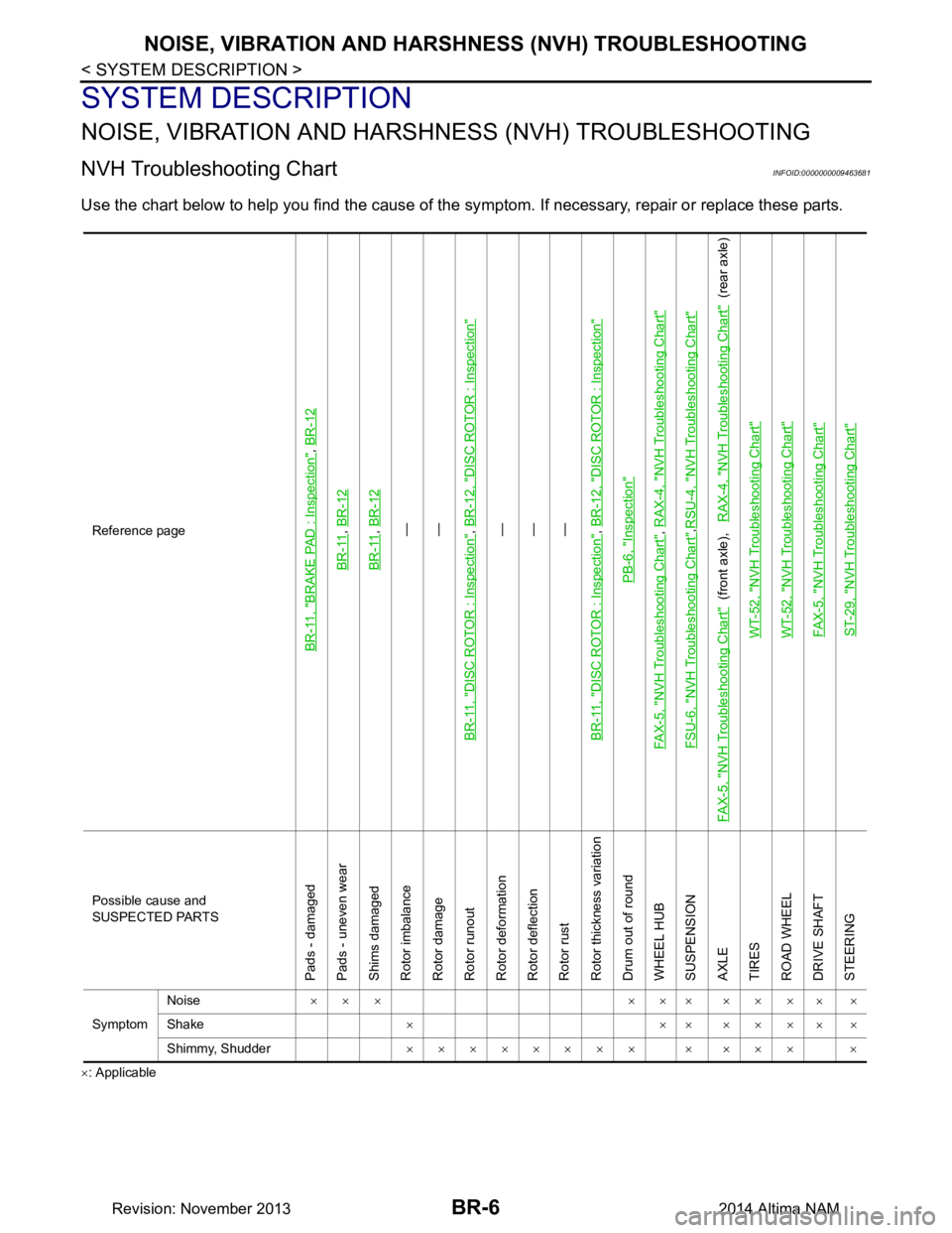
Use the chart below to help you find the cause of the sy mptom. If necessary, repair or replace these parts.
×: ApplicableReference page
BR-11, "BRAKE PAD : Inspection"
,
BR-12
BR-11
, BR-12
BR-11
, BR-12—
—
BR-11, "DISC ROTOR : Inspection", BR-12, "DISC ROTOR : Inspection"—
—
—
BR-11, "DISC ROTOR : Inspection", BR-12, "DISC ROTOR : Inspection"
PB-6, "Inspection"
FAX-5, "NVH Troubleshooting Chart"
, RAX-4, "NVH Troubleshooting Chart"
FSU-6, "NVH Troubleshooting Chart"
,RSU-4, "NVH Troubleshooting Chart"
FAX-5, "NVH Troubleshooting Chart"
(front axle), RAX-4, "NVH Troubleshooting Chart"
(rear axle)
WT-52, "NVH Troubleshooting Chart"
WT-52, "NVH Troubleshooting Chart"FAX-5, "NVH Troubleshooting Chart"ST-29, "NVH Troubleshooting Chart"
Possible cause and
SUSPECTED PARTS
Pads - damaged
Pads - uneven wear
Shims damaged
Rotor imbalance
Rotor damage
Rotor runout
Rotor deformation
Rotor deflection
Rotor rust
Rotor thickness variation
Drum out of round
WHEEL HUB
SUSPENSION
AXLE
TIRES
ROAD WHEEL
DRIVE SHAFT
STEERING
Symptom Noise
××× ××× ×××
××
Shake × ×× ×××
××
Shimmy, Shudder ×××××××× × ××× ×
Revision: November 20132014 Altima NAM
Page 103 of 4801
BRAKE PEDALBR-7
< BASIC INSPECTION >
C
D E
G H
I
J
K L
M A
B
BR
N
O P
BASIC INSPECTION
BRAKE PEDAL
InspectionINFOID:0000000009463682
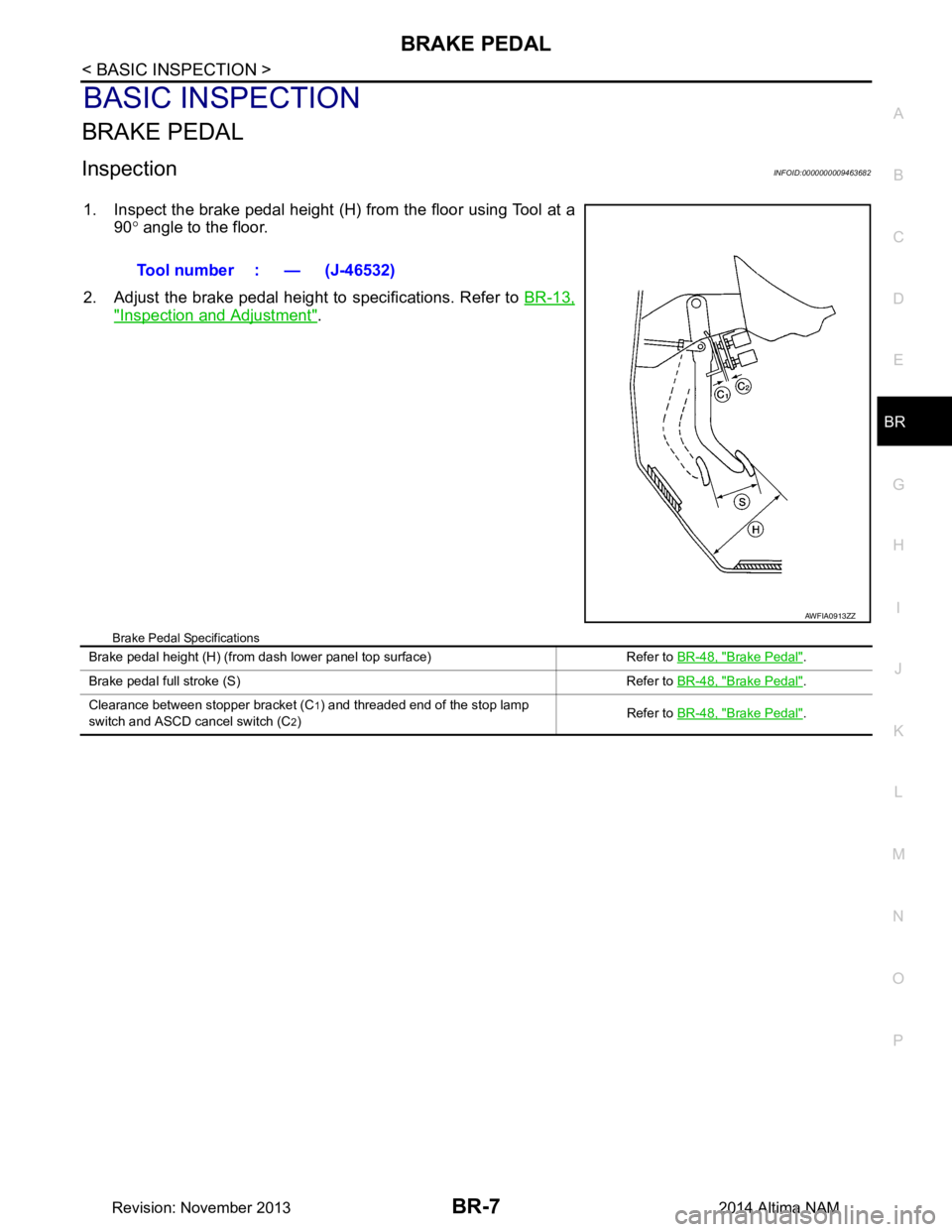
1. Inspect the brake pedal height (H) from the floor using Tool at a 90° angle to the floor.
2. Adjust the brake pedal height to specifications. Refer to BR-13,
"Inspection and Adjustment".
Brake Pedal Specifications
Tool number : — (J-46532)
AWFIA0913ZZ
Brake pedal height (H) (from dash lower panel top surface) Refer to BR-48, "Brake Pedal".
Brake pedal full stroke (S) Refer to BR-48, "Brake Pedal"
.
Clearance between stopper bracket (C
1) and threaded end of the stop lamp
switch and ASCD cancel switch (C
2) Refer to
BR-48, "Brake Pedal".
Revision: November 20132014 Altima NAM
Page 104 of 4801
BR-8
< BASIC INSPECTION >
BRAKE FLUID
BRAKE FLUID
InspectionINFOID:0000000009463683
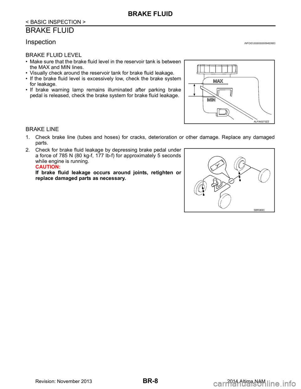
BRAKE FLUID LEVEL
• Make sure that the brake fluid level in the reservoir tank is betweenthe MAX and MIN lines.
• Visually check around the reservoir tank for brake fluid leakage.
• If the brake fluid level is excessively low, check the brake system for leakage.
• If brake warning lamp remains illuminated after parking brake pedal is released, check the brake system for brake fluid leakage.
BRAKE LINE
1. Check brake line (tubes and hoses) for cracks, deterioration or other damage. Replace any damaged
parts.
2. Check for brake fluid leakage by depressing brake pedal under a force of 785 N (80 kg-f, 177 lb-f) for approximately 5 seconds
while engine is running.
CAUTION:
If brake fluid leakage occurs around joints, retighten or
replace damaged parts as necessary.
ALFIA0273ZZ
SBR389C
Revision: November 20132014 Altima NAM
Page 105 of 4801

BRAKE MASTER CYLINDERBR-9
< BASIC INSPECTION >
C
D E
G H
I
J
K L
M A
B
BR
N
O P
BRAKE MASTER CYLINDER
InspectionINFOID:0000000009463684
Check for brake fluid leakage at the following areas:
• Master cylinder mounting face
• Reservoir tank mounting face
• Brake tube and brake tube connections
• Brake hose and brake hose connections
If any brake fluid leakage is found, repair as necessary.
On Board InspectionINFOID:0000000009463685
LEAK INSPECTION
Check for leaks in the master cylinder installation surf ace, reservoir tank installation surface, and brake pipe
and hose connections.
Revision: November 20132014 Altima NAM
Page 106 of 4801
BR-10
< BASIC INSPECTION >
BRAKE BOOSTER
BRAKE BOOSTER
InspectionINFOID:0000000009463686
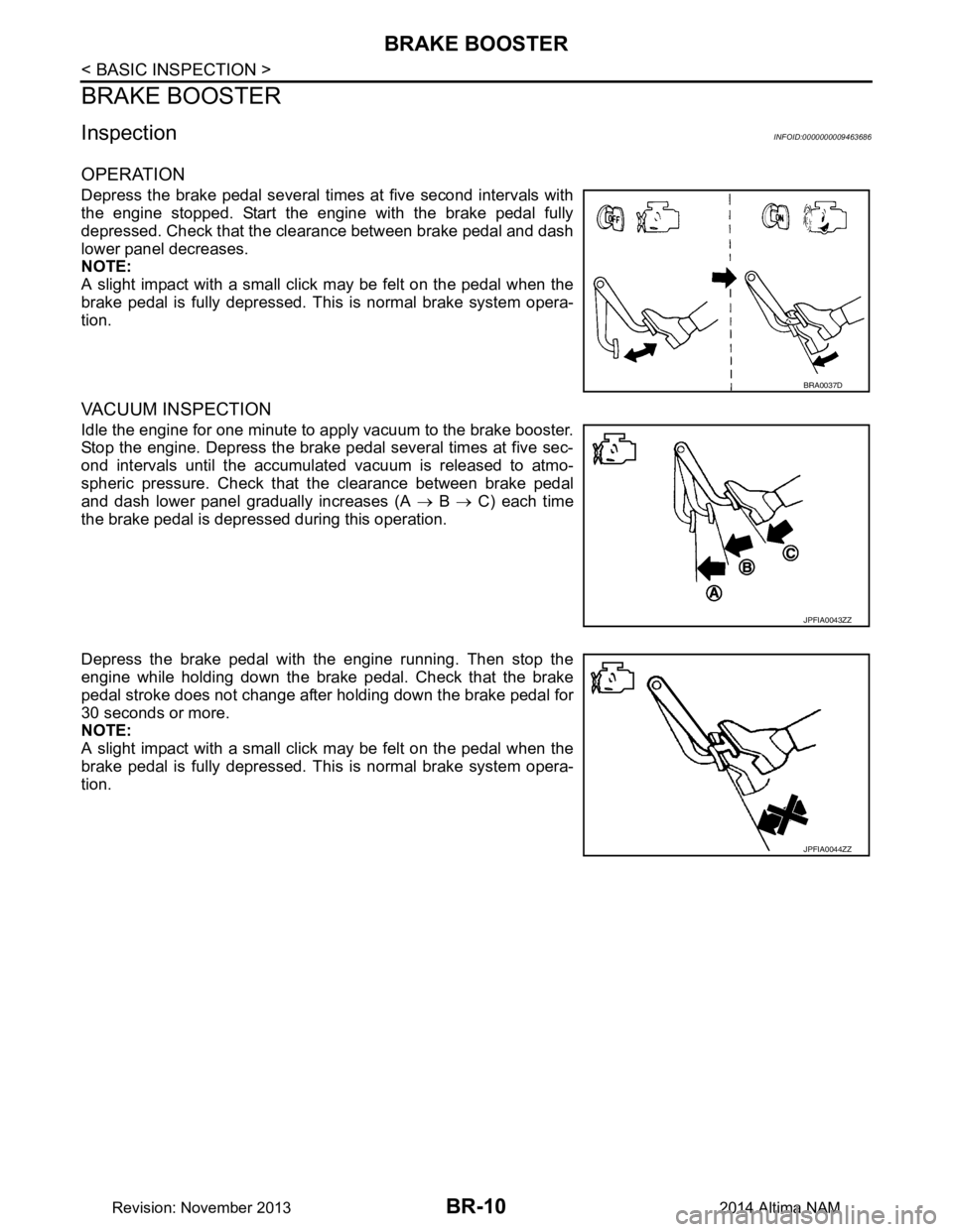
OPERATION
Depress the brake pedal several times at five second intervals with
the engine stopped. Start the engine with the brake pedal fully
depressed. Check that the cl earance between brake pedal and dash
lower panel decreases.
NOTE:
A slight impact with a small click may be felt on the pedal when the
brake pedal is fully depressed. Th is is normal brake system opera-
tion.
VACUUM INSPECTION
Idle the engine for one minute to apply vacuum to the brake booster.
Stop the engine. Depress the brake pedal several times at five sec-
ond intervals until the accumulated vacuum is released to atmo-
spheric pressure. Check that the clearance between brake pedal
and dash lower panel gradually increases (A → B → C) each time
the brake pedal is depressed during this operation.
Depress the brake pedal with the engine running. Then stop the
engine while holding down the brake pedal. Check that the brake
pedal stroke does not change after holding down the brake pedal for
30 seconds or more.
NOTE:
A slight impact with a small click may be felt on the pedal when the
brake pedal is fully depressed. Th is is normal brake system opera-
tion.
BRA0037D
JPFIA0043ZZ
JPFIA0044ZZ
Revision: November 20132014 Altima NAM
Page 107 of 4801
FRONT DISC BRAKEBR-11
< BASIC INSPECTION >
C
D E
G H
I
J
K L
M A
B
BR
N
O P
FRONT DISC BRAKE
BRAKE PAD
BRAKE PAD : InspectionINFOID:0000000009463687
PA D W E A R
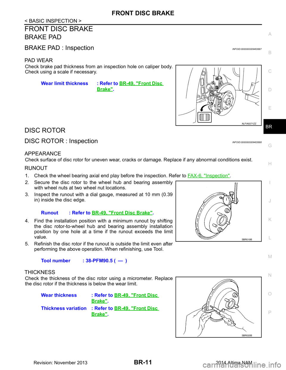
Check brake pad thickness from an inspection hole on caliper body.
Check using a scale if necessary.
DISC ROTOR
DISC ROTOR : InspectionINFOID:0000000009463688
APPEARANCE
Check surface of disc rotor for uneven wear, cracks or damage. Replace if any abnormal conditions exist.
RUNOUT
1. Check the wheel bearing axial end play before the inspection. Refer to FAX-6, "Inspection".
2. Secure the disc rotor to the wheel hub and bearing assembly with wheel nuts at two wheel nut locations.
3. Inspect the runout with a dial gauge, measured at 10 mm (0.39 in) inside the disc edge.
4. Find the installation position with a minimum runout by shifting the disc rotor-to-wheel hub and bearing assembly installation
position by one hole at a time if the runout exceeds the limit
value.
5. Refinish the disc rotor if the runout is outside the limit even after performing the above operation. When refinishing, use Tool.
THICKNESS
Check the thickness of the disc rotor using a micrometer. Replace
the disc rotor if the thick ness is below the wear limit.
Wear limit thickness : Refer to
BR-49, "Front Disc
Brake".
ALFIA0271ZZ
Runout : Refer to BR-49, "Front Disc Brake".
Tool number : 38-PFM90.5 ( — )
SBR019B
Wear thickness : Refer to BR-49, "Front Disc
Brake".
Thickness variation : Refer to BR-49, "Front Disc
Brake".
SBR020B
Revision: November 20132014 Altima NAM
Page 108 of 4801
BR-12
< BASIC INSPECTION >
REAR DISC BRAKE
REAR DISC BRAKE
BRAKE PAD
BRAKE PAD : InspectionINFOID:0000000009463689
PA D W E A R
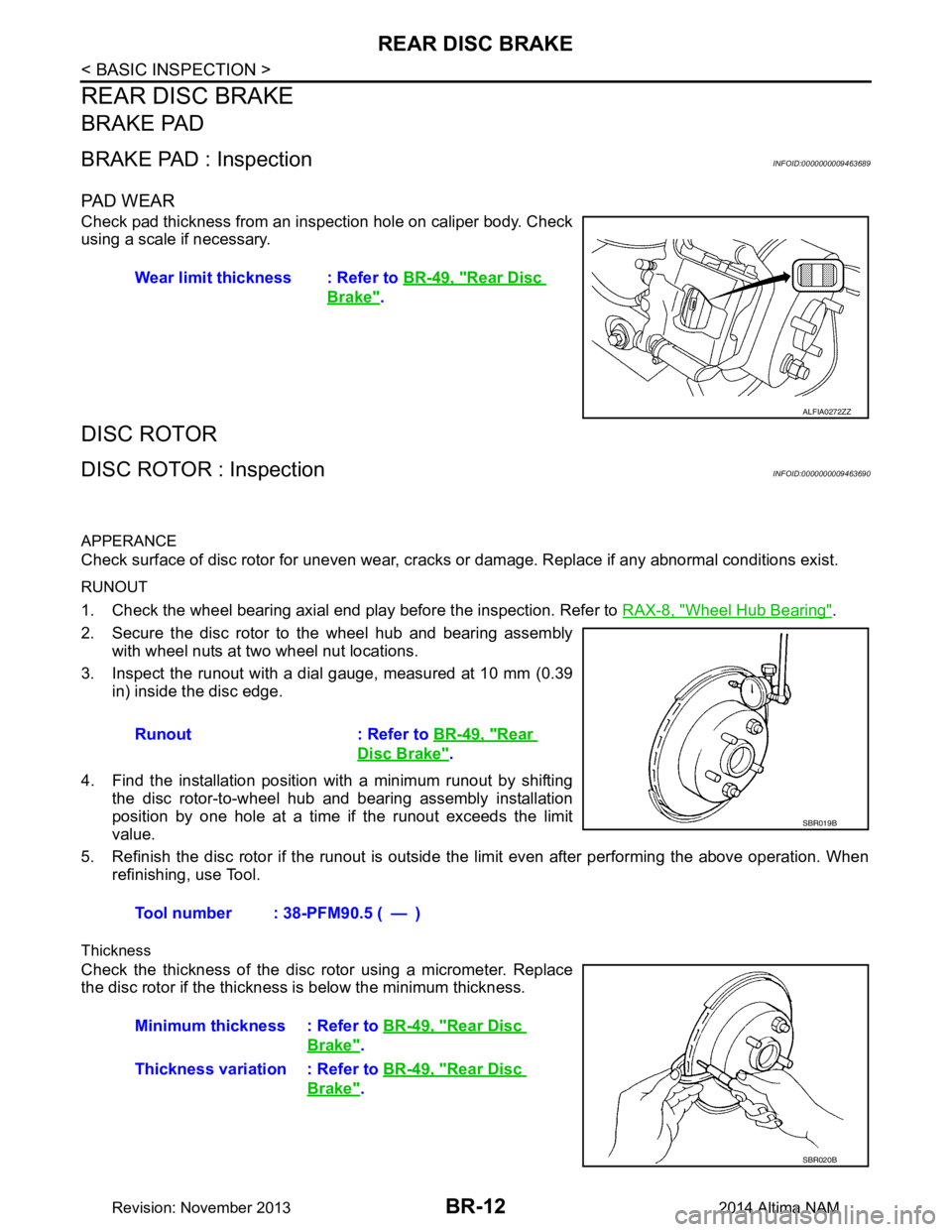
Check pad thickness from an inspection hole on caliper body. Check
using a scale if necessary.
DISC ROTOR
DISC ROTOR : InspectionINFOID:0000000009463690
APPERANCE
Check surface of disc rotor for uneven wear, cracks or damage. Replace if any abnormal conditions exist.
RUNOUT
1. Check the wheel bearing axial end play before the inspection. Refer to RAX-8, "Wheel Hub Bearing".
2. Secure the disc rotor to the wheel hub and bearing assembly with wheel nuts at two wheel nut locations.
3. Inspect the runout with a dial gauge, measured at 10 mm (0.39 in) inside the disc edge.
4. Find the installation position with a minimum runout by shifting the disc rotor-to-wheel hub and bearing assembly installation
position by one hole at a time if the runout exceeds the limit
value.
5. Refinish the disc rotor if the runout is outside t he limit even after performing the above operation. When
refinishing, use Tool.
Thickness
Check the thickness of the disc ro tor using a micrometer. Replace
the disc rotor if the thickness is below the minimum thickness. Wear limit thickness : Refer to
BR-49, "Rear Disc
Brake".
ALFIA0272ZZ
Runout : Refer to BR-49, "Rear
Disc Brake".
Tool number : 38-PFM90.5 ( — )
SBR019B
Minimum thickness : Refer to BR-49, "Rear Disc
Brake".
Thickness variation : Refer to BR-49, "Rear Disc
Brake".
SBR020B
Revision: November 20132014 Altima NAM
Page 109 of 4801
BRAKE PEDALBR-13
< PERIODIC MAINTENANCE >
C
D E
G H
I
J
K L
M A
B
BR
N
O P
PERIODIC MAINTENANCE
BRAKE PEDAL
Inspection and AdjustmentINFOID:0000000009463691
ADJUSTMENT
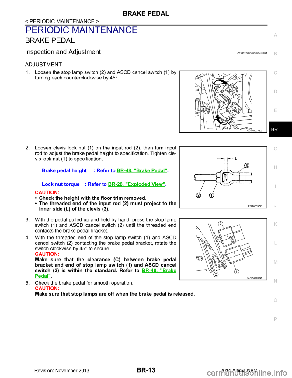
1. Loosen the stop lamp switch (2) and ASCD cancel switch (1) by turning each counterclockwise by 45 °.
2. Loosen clevis lock nut (1) on the input rod (2), then turn input rod to adjust the brake pedal height to specification. Tighten cle-
vis lock nut (1) to specification.
CAUTION:
• Check the height with the floor trim removed.
• The threaded end of the input rod (2) must project to the
inner side (L) of the clevis (3).
3. With the pedal pulled up and held by hand, press the stop lamp switch (1) and ASCD cancel switch (2) until the threaded end
contacts the brake pedal bracket.
4. With the threaded end of the stop lamp switch (1) and ASCD cancel switch (2) contacting the brake pedal bracket, rotate the
switch clockwise by 45 ° to secure.
CAUTION:
Make sure that the clearance (C) between brake pedal
bracket and end of stop lamp switch (1) and ASCD cancel
switch (2) is within the standard. Refer to BR-48, "Brake
Pedal".
5. Check the brake pedal for smooth operation. CAUTION:
Make sure that stop lamps are off when the brake pedal is released.
ALFIA0277ZZ
Brake pedal height : Refer to BR-48, "Brake Pedal".
Lock nut torque : Refer to BR-28, "Exploded View"
.
JPFIA0003ZZ
ALFIA0278ZZ
Revision: November 20132014 Altima NAM
Page 110 of 4801
BR-14
< PERIODIC MAINTENANCE >
BRAKE FLUID
BRAKE FLUID
Drain and RefillINFOID:0000000009463692
CAUTION:
• Do not spill or splash brake fluid on painted surf aces. Brake fluid may damage paint. If brake fluid is
splashed on painted areas, wash it away with water immediately.
• Prior to repair, turn the ignition switch OFF, disconnect the ABS actuator and electric unit (control
unit) connector or negative battery terminal. Refer to PG-73, "Removal and Installation (Battery)"
.
• Refill brake system with new brake fluid. Refer to MA-11, "FOR USA AND CANADA : Fluids and
Lubricants".
• Do not reuse drained brake fluid.
DRAINING
1. Turn ignition switch OFF and disconnect ABS actuat or and electric unit (control unit) connector or nega-
tive battery terminal. Refer to PG-73, "Removal and Installation (Battery)"
.
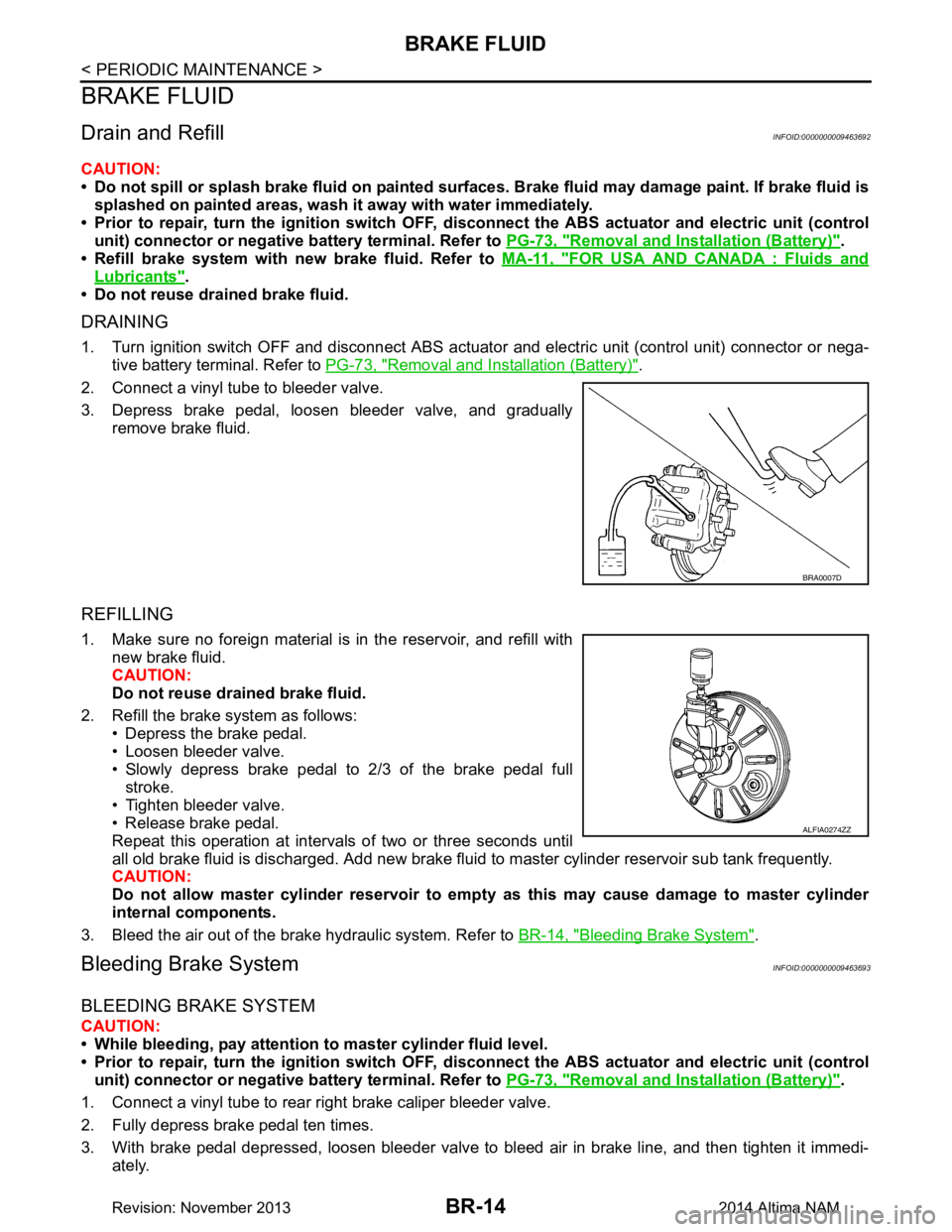
2. Connect a vinyl tube to bleeder valve.
3. Depress brake pedal, loosen bleeder valve, and gradually remove brake fluid.
REFILLING
1. Make sure no foreign material is in the reservoir, and refill withnew brake fluid.
CAUTION:
Do not reuse drained brake fluid.
2. Refill the brake system as follows: • Depress the brake pedal.
• Loosen bleeder valve.
• Slowly depress brake pedal to 2/3 of the brake pedal full
stroke.
• Tighten bleeder valve.
• Release brake pedal.
Repeat this operation at intervals of two or three seconds until
all old brake fluid is discharged. Add new brake flui d to master cylinder reservoir sub tank frequently.
CAUTION:
Do not allow master cylinder reservoir to empt y as this may cause damage to master cylinder
internal components.
3. Bleed the air out of the brake hydraulic system. Refer to BR-14, "Bleeding Brake System"
.
Bleeding Brake SystemINFOID:0000000009463693
BLEEDING BRAKE SYSTEM
CAUTION:
• While bleeding, pay attention to master cylinder fluid level.
• Prior to repair, turn the ignition switch OFF, disconnect the ABS actuator and electric unit (control
unit) connector or negative battery terminal. Refer to PG-73, "Removal and Installation (Battery)"
.
1. Connect a vinyl tube to rear right brake caliper bleeder valve.
2. Fully depress brake pedal ten times.
3. With brake pedal depressed, loosen bleeder valve to bleed air in brake line, and then tighten it immedi-
ately.
BRA0007D
ALFIA0274ZZ
Revision: November 20132014 Altima NAM