NISSAN TEANA 2014 Service Manual
Manufacturer: NISSAN, Model Year: 2014, Model line: TEANA, Model: NISSAN TEANA 2014Pages: 4801, PDF Size: 51.2 MB
Page 121 of 4801
BRAKE PIPINGBR-25
< REMOVAL AND INSTALLATION >
C
D E
G H
I
J
K L
M A
B
BR
N
O P
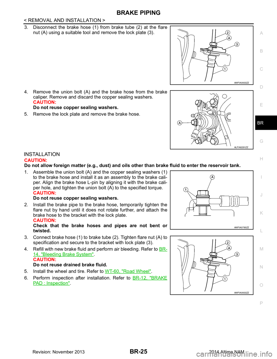
3. Disconnect the brake hose (1) from brake tube (2) at the flare nut (A) using a suitable tool and remove the lock plate (3).
4. Remove the union bolt (A) and the brake hose from the brake caliper. Remove and discard the copper sealing washers.
CAUTION:
Do not reuse copper sealing washers.
5. Remove the lock plate and remove the brake hose.
INSTALLATION
CAUTION:
Do not allow foreign matte r (e.g., dust) and oils other than brake fluid to enter the reservoir tank.
1. Assemble the union bolt (A) and the copper sealing washers (1) to the brake hose and install it as an assembly to the brake cali-
per. Align the brake hose L-pin by aligning it with the brake cali-
per hole, and tighten the union bolt (A) to the specified torque.
CAUTION:
Do not reuse copper sealing washers.
2. Install the brake pipe to the brake hose, temporarily tighten the flare nut by hand until it does not rotate further, and attach the
brake hose to the bracket with the lock plate.
CAUTION:
Check that the brake hoses and pipes are not bent or
twisted.
3. Connect brake hose (1) to brake tube (2). Tighten flare nut (A) to specification and secure to the bracket with lock plate (3).
4. Refill with new brake fluid and perform air bleeding. Refer to BR-
14, "Bleeding Brake System".
CAUTION:
Do not reuse drained brake fluid.
5. Install the wheel and tire. Refer to WT-60, "Road Wheel"
.
6. Perform inspection after installation. Refer to BR-12, "BRAKE
PAD : Inspection".
AWFIA0933ZZ
ALFIA0291ZZ
AWFIA0795ZZ
AWFIA0933ZZ
Revision: November 20132014 Altima NAM
Page 122 of 4801
BR-26
< REMOVAL AND INSTALLATION >
BRAKE MASTER CYLINDER
BRAKE MASTER CYLINDER
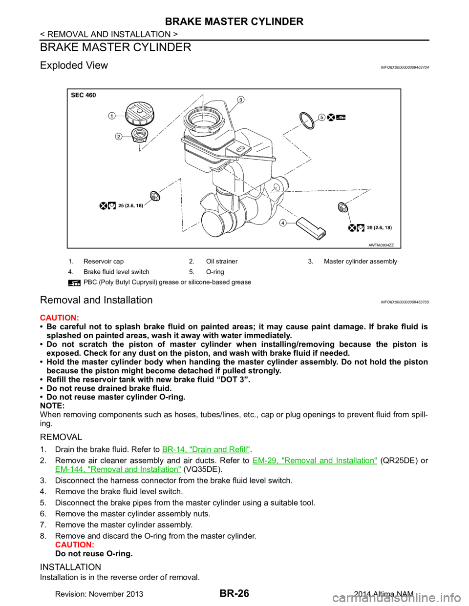
Exploded ViewINFOID:0000000009463704
Removal and InstallationINFOID:0000000009463705
CAUTION:
• Be careful not to splash brake fluid on painted areas; it may cause paint damage. If brake fluid is
splashed on painted areas, wash it away with water immediately.
• Do not scratch the piston of master cylinder when installing/removing because the piston is
exposed. Check for any dust on the piston , and wash with brake fluid if needed.
• Hold the master cylinder body when handing the master cylinder assembly. Do not hold the piston
because the piston might become detached if pulled strongly.
• Refill the reservoir tank wi th new brake fluid “DOT 3”.
• Do not reuse drained brake fluid.
• Do not reuse master cylinder O-ring.
NOTE:
When removing components such as hoses, tubes/lines, etc. , cap or plug openings to prevent fluid from spill-
ing.
REMOVAL
1. Drain the brake fluid. Refer to BR-14, "Drain and Refill".
2. Remove air cleaner assembly and air ducts. Refer to EM-29, "Removal and Installation"
(QR25DE) or
EM-144, "Removal and Installation"
(VQ35DE).
3. Disconnect the harness connector from the brake fluid level switch.
4. Remove the brake fluid level switch.
5. Disconnect the brake pipes from the master cylinder using a suitable tool.
6. Remove the master cylinder assembly nuts.
7. Remove the master cylinder assembly.
8. Remove and discard the O-ring from the master cylinder. CAUTION:
Do not reuse O-ring.
INSTALLATION
Installation is in the reverse order of removal.
1. Reservoir cap 2. Oil strainer 3. Master cylinder assembly
4. Brake fluid level switch 5. O-ring PBC (Poly Butyl Cuprysil) grease or silicone-based grease
AWFIA0934ZZ
Revision: November 20132014 Altima NAM
Page 123 of 4801
BRAKE MASTER CYLINDERBR-27
< REMOVAL AND INSTALLATION >
C
D E
G H
I
J
K L
M A
B
BR
N
O P
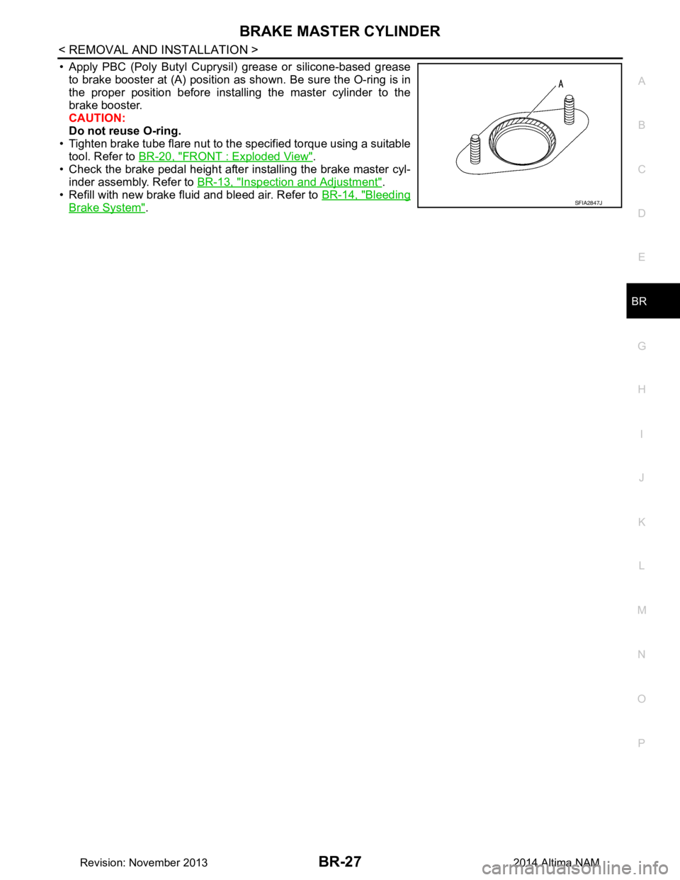
• Apply PBC (Poly Butyl Cuprysil) grease or silicone-based grease to brake booster at (A) position as shown. Be sure the O-ring is in
the proper position before installing the master cylinder to the
brake booster.
CAUTION:
Do not reuse O-ring.
• Tighten brake tube flare nut to the specified torque using a suitable tool. Refer to BR-20, "FRONT : Exploded View"
.
• Check the brake pedal height after installing the brake master cyl-
inder assembly. Refer to BR-13, "Inspection and Adjustment"
.
• Refill with new brake fluid and bleed air. Refer to BR-14, "Bleeding
Brake System".SFIA2847J
Revision: November 20132014 Altima NAM
Page 124 of 4801
BR-28
< REMOVAL AND INSTALLATION >
BRAKE BOOSTER
BRAKE BOOSTER
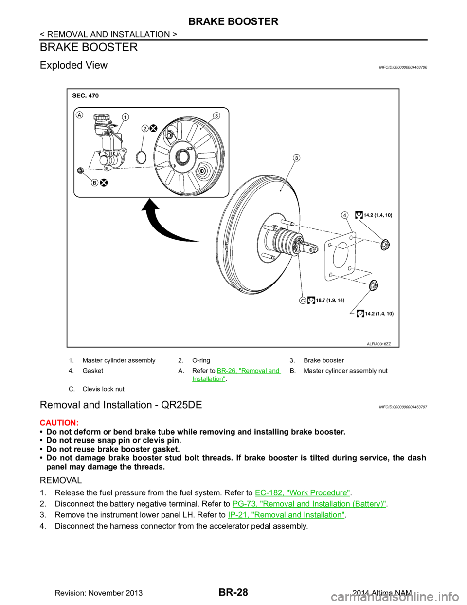
Exploded ViewINFOID:0000000009463706
Removal and Installation - QR25DEINFOID:0000000009463707
CAUTION:
• Do not deform or bend brake tube whil e removing and installing brake booster.
• Do not reuse snap pin or clevis pin.
• Do not reuse brake booster gasket.
• Do not damage brake booster stud bolt threads. If brake booster is tilted during service, the dash
panel may damage the threads.
REMOVAL
1. Release the fuel pressure from the fuel system. Refer to EC-182, "Work Procedure".
2. Disconnect the battery negative terminal. Refer to PG-73, "Removal and Installation (Battery)"
.
3. Remove the instrument lower panel LH. Refer to IP-21, "Removal and Installation"
.
4. Disconnect the harness connector from the accelerator pedal assembly.
1. Master cylinder assembly 2. O-ring 3. Brake booster
4. Gasket A. Refer to BR-26, "Removal and
Installation".B. Master cylinder assembly nut
C. Clevis lock nut
ALFIA0318ZZ
Revision: November 20132014 Altima NAM
Page 125 of 4801

BRAKE BOOSTERBR-29
< REMOVAL AND INSTALLATION >
C
D E
G H
I
J
K L
M A
B
BR
N
O P
5. Remove the snap pin (1) and clevis pin (2) from the brake pedal. CAUTION:
Do not reuse snap pin or clevis pin.
6. Disconnect the harness connectors from the ASCD cancel switch and stop lamp switch.
7. Disconnect the steering column assembly pinch bolt and position the steering column shaft aside. Refer to
ST-33, "Exploded View"
.
8. Remove the brake master cylinder. Refer to BR-26, "Removal and Installation"
.
9. Disconnect the fuel line main connections. Refer to FL-5, "Quick Connector"
.
10. Remove the cowl top. Refer to EXT-24, "Removal and Installation"
.
11. Remove the strut tower bar. Refer to FSU-19, "Exploded View"
.
12. Remove the wiper drive assembly. Refer to WW-64, "Removal and Installation"
.
13. Remove the cowl top extension.
14. Disconnect the vacuum hose from the brake booster.
15. Disconnect the active boost sensor harness connector.
16. Remove brake booster nuts.
17. Remove the brake booster.
18. Remove and discard the brake booster gasket. CAUTION:
Do not reuse brake booster gasket.
INSTALLATION
Installation is in the reverse order of removal.
• Prior to installation, loosen clevis lock nut (1) and adjust input rod (2) to the specified value (B).
• After input rod adjustment (B), temporarily tighten clevis lock nut for installation of brake booster.
• Connect the battery negative terminal. Refer to PG-7, "ADDITIONAL SERVICE WHEN REMOVING BAT-
TERY NEGATIVE TERMINAL : Special Repair Requirement".
Removal and Installation - VQ35DEINFOID:0000000009463708
CAUTION:
• Do not deform or bend brake tube while removing and installing brake booster.
• Do not reuse snap pin or clevis pin.
• Do not reuse brake booster gasket.
• Do not damage brake booster stud bolt threads. If brake booster is tilted during service, the dash
panel may damage the threads.
REMOVAL
1. Release the fuel pressure from the fuel system. Refer to EC-687, "Work Procedure".
JPFIA0019ZZ
Length (B) : Refer to BR-49, "Brake Booster".
ALFIA0299ZZ
Revision: November 20132014 Altima NAM
Page 126 of 4801

BR-30
< REMOVAL AND INSTALLATION >
BRAKE BOOSTER
2. Disconnect the battery negative cable. Refer to PG-73, "Removal and Installation (Battery)".
3. Remove the instrument lower panel LH. Refer to IP-21, "Removal and Installation"
.
4. Remove accelerator pedal assembly. Refer to ACC-3, "Removal and Installation"
.
5. Remove the brake pedal. Refer to BR-18, "Removal and Installation"
.
6. Loosen the clevis lock nut (A) and remove the clevis bracket (B) from the input rod (C).
7. Remove the brake master cylinder. Refer to BR-26, "Removal and Installation"
.
8. Remove the vacuum hose. Refer to BR-31, "Exploded View"
.
9. Disconnect the fuel line main connections. Refer to FL-5, "Quick Connector"
.
10. Remove the cowl top. Refer to EXT-24, "Removal and Installation"
.
11. Remove the strut tower bar. Refer to FSU-19, "Exploded View"
.
12. Remove the wiper drive assembly. Refer to WW-64, "Removal and Installation"
.
13. Remove the cowl top extension.
14. Disconnect the active boost sensor harness connector.
15. Remove the brake booster.
16. Remove and discard the brake booster gasket. CAUTION:
Do not reuse brake booster gasket.
INSTALLATION
Installation is in the reverse order of removal.
• Prior to installation, loosen clevis lock nut (1) and adjust input rod (2) to the specified value (B).
• After input rod adjustment (B), temporarily tighten clevis lock nut for installation of brake booster.
• Connect the battery negative terminal. Refer to PG-7, "ADDITIONAL SERVICE WHEN REMOVING BAT-
TERY NEGATIVE TERMINAL : Special Repair Requirement".
:Front
ALFIA0319ZZ
Length (B) : Refer to BR-49, "Brake Booster".
ALFIA0299ZZ
Revision: November 20132014 Altima NAM
Page 127 of 4801
VACUUM LINESBR-31
< REMOVAL AND INSTALLATION >
C
D E
G H
I
J
K L
M A
B
BR
N
O P
VACUUM LINES
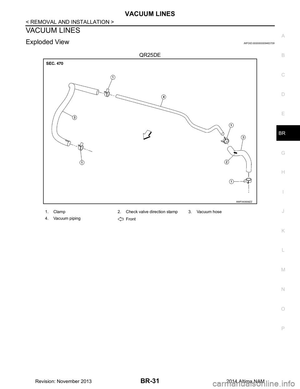
Exploded ViewINFOID:0000000009463709
QR25DE
AWFIA0939ZZ
1. Clamp 2. Check valve direction stamp 3. Vacuum hose
4. Vacuum piping Front
Revision: November 20132014 Altima NAM
Page 128 of 4801
BR-32
< REMOVAL AND INSTALLATION >
VACUUM LINES
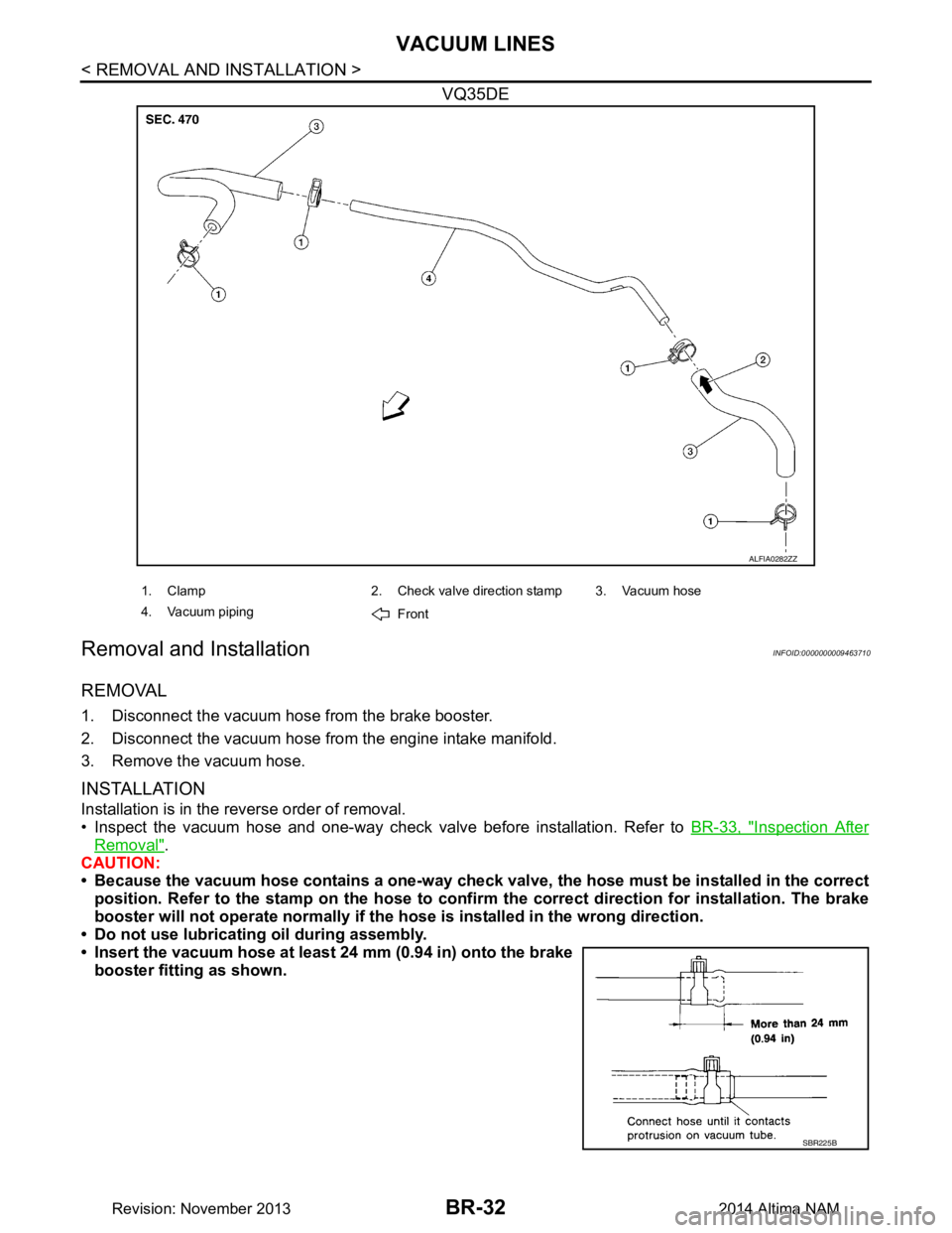
VQ35DE
Removal and InstallationINFOID:0000000009463710
REMOVAL
1. Disconnect the vacuum hose from the brake booster.
2. Disconnect the vacuum hose from the engine intake manifold.
3. Remove the vacuum hose.
INSTALLATION
Installation is in the reverse order of removal.
• Inspect the vacuum hose and one-way check valve before installation. Refer to BR-33, "Inspection After
Removal".
CAUTION:
• Because the vacuum hose contains a one-way check val ve, the hose must be installed in the correct
position. Refer to the stamp on the hose to confi rm the correct direction for installation. The brake
booster will not operate normally if the ho se is installed in the wrong direction.
• Do not use lubricating oil during assembly.
• Insert the vacuum hose at least 24 mm (0.94 in) onto the brake booster fitting as shown.
ALFIA0282ZZ
1. Clamp 2. Check valve direction stamp 3. Vacuum hose
4. Vacuum piping Front
SBR225B
Revision: November 20132014 Altima NAM
Page 129 of 4801
VACUUM LINESBR-33
< REMOVAL AND INSTALLATION >
C
D E
G H
I
J
K L
M A
B
BR
N
O P
Inspection After RemovalINFOID:0000000009463711
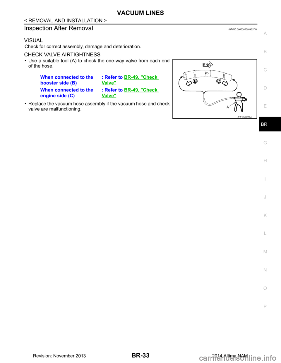
VISUAL
Check for correct assembly, damage and deterioration.
CHECK VALVE AIRTIGHTNESS
• Use a suitable tool (A) to check the one-way valve from each end of the hose.
• Replace the vacuum hose assembly if the vacuum hose and check valve are malfunctioning. When connected to the
booster side (B) : Refer to
BR-49, "Check
Valve"
When connected to the
engine side (C) : Refer to
BR-49, "Check
Valve"
JPFIA0024ZZ
Revision: November 20132014 Altima NAM
Page 130 of 4801
BR-34
< REMOVAL AND INSTALLATION >
FRONT DISC BRAKE
FRONT DISC BRAKE
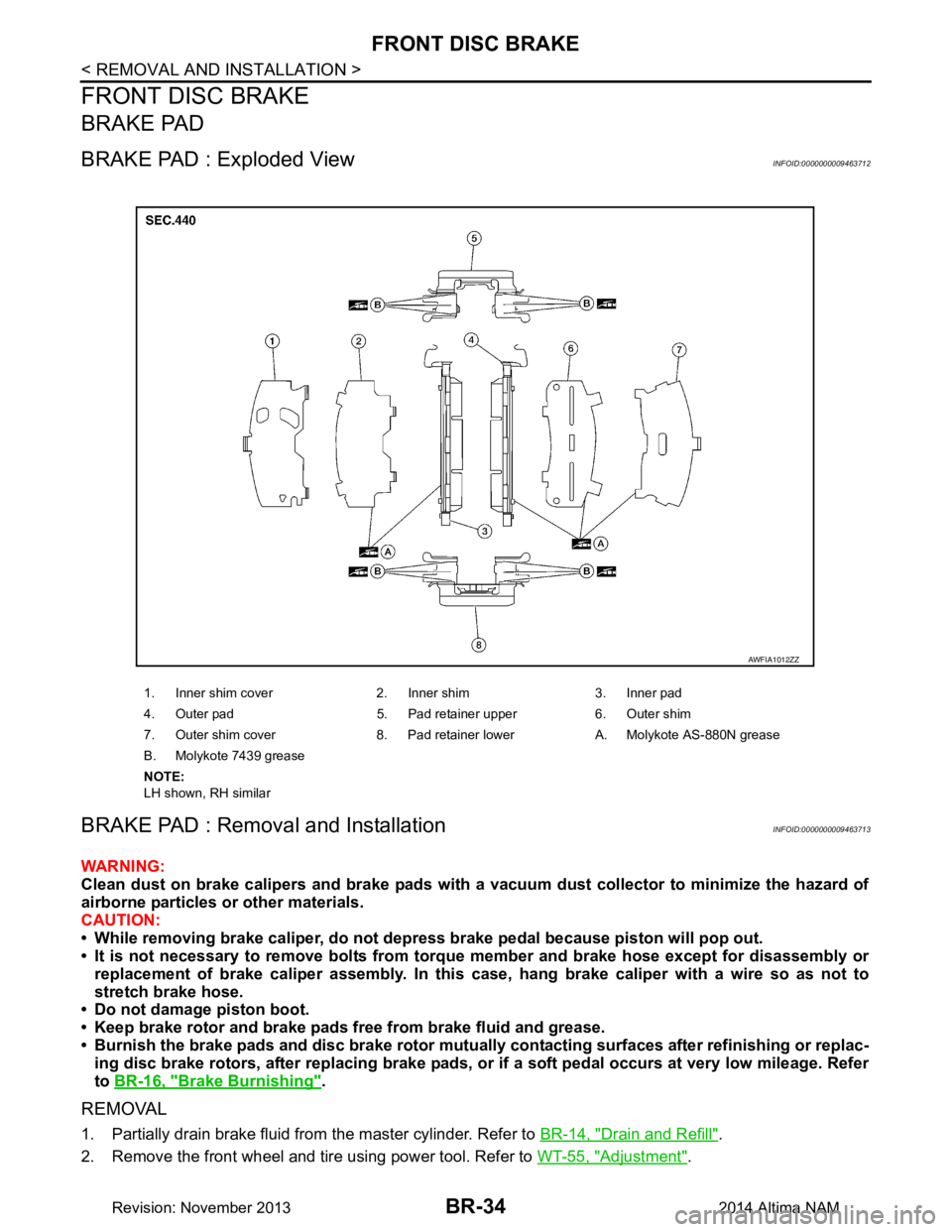
BRAKE PAD
BRAKE PAD : Exploded ViewINFOID:0000000009463712
BRAKE PAD : Removal and InstallationINFOID:0000000009463713
WARNING:
Clean dust on brake calipers and brake pads with a vacuum dust collector to minimize the hazard of
airborne particles or other materials.
CAUTION:
• While removing brake caliper, do not depr ess brake pedal because piston will pop out.
• It is not necessary to remove bolts from torque member and brake hose except for disassembly or
replacement of brake caliper assembly. In this case, hang brake caliper with a wire so as not to
stretch brake hose.
• Do not damage piston boot.
• Keep brake rotor and brake pads free from brake fluid and grease.
• Burnish the brake pads and disc brake rotor mutual ly contacting surfaces after refinishing or replac-
ing disc brake rotors, after replacing brake pads, or if a soft pedal occurs at very low mileage. Refer
to BR-16, "Brake Burnishing"
.
REMOVAL
1. Partially drain brake fluid from the master cylinder. Refer to BR-14, "Drain and Refill".
2. Remove the front wheel and tire using power tool. Refer to WT-55, "Adjustment"
.
1. Inner shim cover 2. Inner shim 3. Inner pad
4. Outer pad 5. Pad retainer upper 6. Outer shim
7. Outer shim cover 8. Pad retainer lower A. Molykote AS-880N grease
B. Molykote 7439 grease
NOTE:
LH shown, RH similar
AWFIA1012ZZ
Revision: November 20132014 Altima NAM