NISSAN TEANA 2014 Service Manual
Manufacturer: NISSAN, Model Year: 2014, Model line: TEANA, Model: NISSAN TEANA 2014Pages: 4801, PDF Size: 51.2 MB
Page 4741 of 4801
WW-6
< SYSTEM DESCRIPTION >
SYSTEM
SYSTEM
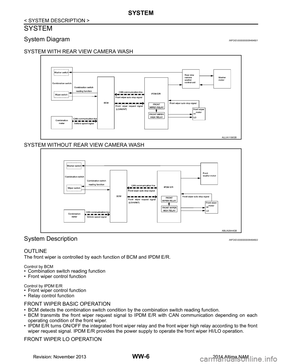
System DiagramINFOID:0000000009464601
SYSTEM WITH REAR VIEW CAMERA WASH
SYSTEM WITHOUT REAR VIEW CAMERA WASH
System DescriptionINFOID:0000000009464602
OUTLINE
The front wiper is controlled by each function of BCM and IPDM E/R.
Control by BCM
• Combination switch reading function
• Front wiper control function
Control by IPDM E/R
• Front wiper control function
• Relay control function
FRONT WIPER BASIC OPERATION
• BCM detects the combination switch conditi on by the combination switch reading function.
• BCM transmits the front wiper request signal to IPDM E/R with CAN communication depending on each
operating condition of the front wiper.
• IPDM E/R turns ON/OFF the integrated front wiper rela y and the front wiper high relay according to the front
wiper request signal. IPDM E/R provides the power supply to operate the front wiper HI/LO operation.
FRONT WIPER LO OPERATION
ALLIA1156GB
ABLIA2944GB
Revision: November 20132014 Altima NAMRevision: November 20132014 Altima NAM
Page 4742 of 4801
SYSTEMWW-7
< SYSTEM DESCRIPTION >
C
D E
F
G H
I
J
K
M A
B
WW
N
O P
• BCM transmits the front wiper request signal (LO) to IPDM E/R with CAN communication according to the
front wiper LO operating condition.
Front wiper LO operating condition- Ignition switch ON
- Front wiper switch LO or front wiper switch MIST (while pressing)
• IPDM E/R turns ON the integrated front wiper rela y according to the front wiper request signal (LO).
FRONT WIPER HI OPERATION
• BCM transmits the front wiper request signal (HI) to IPDM E/R with CAN communication according to the
front wiper HI operating condition.
Front wiper HI operating condition
- Ignition switch ON
- Front wiper switch HI
• IPDM E/R turns ON the integrated front wiper relay and the front wiper high relay according to the front wiper
request signal (HI).
FRONT WIPER INT OPERATION
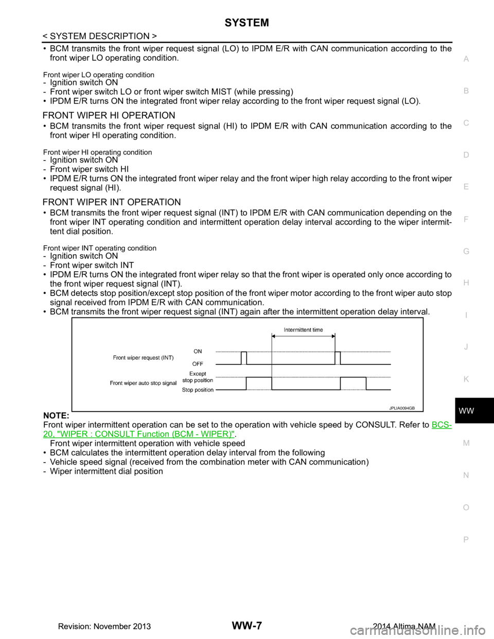
• BCM transmits the front wiper request signal (INT ) to IPDM E/R with CAN communication depending on the
front wiper INT operating condition and intermittent operati on delay interval according to the wiper intermit-
tent dial position.
Front wiper INT operating condition
- Ignition switch ON
- Front wiper switch INT
• IPDM E/R turns ON the integrated front wiper relay so that the front wiper is operated only once according to
the front wiper request signal (INT).
• BCM detects stop position/except stop position of the front wiper motor according to the front wiper auto stop
signal received from IPDM E/R with CAN communication.
• BCM transmits the front wiper request signal (INT) again after the intermittent operation delay interval.
NOTE:
Front wiper intermittent operation can be set to the operation with vehicle speed by CONSULT. Refer to BCS-
20, "WIPER : CONSULT Function (BCM - WIPER)".
Front wiper intermittent operation with vehicle speed
• BCM calculates the intermittent operation delay interval from the following
- Vehicle speed signal (received from the combination meter with CAN communication)
- Wiper intermittent dial position
JPLIA0094GB
Revision: November 20132014 Altima NAMRevision: November 20132014 Altima NAM
Page 4743 of 4801
WW-8
< SYSTEM DESCRIPTION >
SYSTEM
*: When without vehicle speed setting
FRONT WIPER AUTO STOP OPERATION
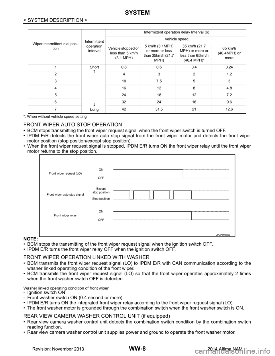
• BCM stops transmitting the front wiper request signal when the front wiper switch is turned OFF.
• IPDM E/R detects the front wiper auto stop signal fr om the front wiper motor and detects the front wiper
motor position (stop position/except stop position).
• When the front wiper request signal is stopped, IPDM E/R turns ON the front wiper relay until the front wiper
motor returns to the stop position.
NOTE:
• BCM stops the transmitting of the front wi per request signal when the ignition switch OFF.
• IPDM E/R turns the front wiper rela y OFF when the ignition switch OFF.
FRONT WIPER OPERATION LINKED WITH WASHER
• BCM transmits the front wiper request signal (LO) to IPDM E/R with CAN communication according to the
washer linked operating condition of the front wiper.
• BCM transmits the front wiper request signal (LO) so that the front wiper operates approximately 2 times
when the front washer s witch OFF is detected.
Washer linked operating condition of front wiper- Ignition switch ON
- Front washer switch ON (0.4 second or more)
• IPDM E/R turns ON the integrated front wiper rela y according to the front wiper request signal (LO).
• The front washer motor is grounded through the combinat ion switch when the front washer switch is ON.
REAR VIEW CAMERA WASHER CONTROL UNIT (if equipped)
• Rear view camera washer control unit detects the co mbination switch condition by the combination switch
reading function.
• Rear view camera washer control unit supplies power and ground to operate the front washer motor.
Wiper intermittent dial posi-
tion Intermittent
operation interval Intermittent operation delay Interval (s)
Vehicle speed
Vehicle stopped or less than 5 km/h (3.1 MPH) 5 km/h (3.1MPH)
or more or less
than 35km/h (21.7
MPH) 35 km/h (21.7
MPH) or more or
less than 65km/h
(40.4 MPH)* 65 km/h
(40.4MPH) or more
1Short ↑
↓
Long 0.8 0.6 0.4 0.24
2 4321.2
3107.553
4161284.8
52418127.2
63224169.6
7 4231.52112.6
JPLIA0095GB
Revision: November 20132014 Altima NAMRevision: November 20132014 Altima NAM
Page 4744 of 4801
SYSTEMWW-9
< SYSTEM DESCRIPTION >
C
D E
F
G H
I
J
K
M A
B
WW
N
O P
Washer linked operating condition of rear view camera washer control unit- Ignition switch ON
- Front washer switch ON (0.4 second or more).
• IPDM E/R turns ON the integrated front wiper relay.
• The washer motor is grounded through the rear view camera washer control unit.
• The rear view camera washer control unit decides to spray the windshield or the rear camera.
Fail-SafeINFOID:0000000009464603
FA I L −SAFE OPERATION
IPDM E/R performs the fail-safe function when the front wiper auto stop circuit is malfunctioning. Refer to
PCS-19, "Fail Safe"
.
Revision: November 20132014 Altima NAMRevision: November 20132014 Altima NAM
Page 4745 of 4801

WW-10
< SYSTEM DESCRIPTION >
DIAGNOSIS SYSTEM (BCM)
DIAGNOSIS SYSTEM (BCM)
COMMON ITEM
COMMON ITEM : CONSULT Function (BCM - COMMON ITEM)INFOID:0000000009944151
CAUTION:
After disconnecting the CONSULT vehicle interface (VI) from the data link connector, the ignition must
be cycled OFF → ON (for at least 5 seconds) → OFF. If this step is not performed, the BCM may not go
to ”sleep mode”, potentially causing a di scharged battery and a no-start condition.
APPLICATION ITEM
CONSULT performs the following functions via CAN communication with BCM.
SYSTEM APPLICATION
BCM can perform the following functions.
Direct Diagnostic Mode Description
Ecu Identification The BCM part number is displayed.
Self Diagnostic Result The BCM self diagnostic results are displayed.
Data Monitor The BCM input/output data is displayed in real time.
Active Test The BCM activates outputs to test components.
Work support The settings for BCM functions can be changed.
Configuration • The vehicle specification can be read and saved.
• The vehicle specification can be written when replacing BCM.
CAN Diag Support Mntr The result of transmit/receive diagnosis of CAN communication is displayed.
System Sub System Direct Diagnostic Mode
Ecu Identification
Self Diagnostic Result
Data Monitor
Active Test
Work support
Configuration
CAN Diag Su pport Mntr
Door lock DOOR LOCK ××××
Rear window defogger REAR DEFOGGER ×××
Warning chime BUZZER ××
Interior room lamp timer INT LAMP ×××
Remote keyless entry system MULTI REMOTE ENT ×××
Exterior lamp HEADLAMP ×××
Wiper and washer WIPER ×××
Turn signal and hazard warning lamps FLASHER ××
Air conditioner AIR CONDITIONER ×
Intelligent Key system INTELLIGENT KEY ××××
Combination switch COMB SW ×
BCM BCM × × ×××
Immobilizer IMMU ×××
Interior room lamp battery saver BATTERY SAVER ××
Trunk open TRUNK ×
Vehicle security system THEFT ALM ×××
Revision: November 20132014 Altima NAMRevision: November 20132014 Altima NAM
Page 4746 of 4801

DIAGNOSIS SYSTEM (BCM)WW-11
< SYSTEM DESCRIPTION >
C
D E
F
G H
I
J
K
M A
B
WW
N
O P
WIPER
WIPER : CONSULT Func tion (BCM - WIPER)INFOID:0000000009944152
CAUTION:
After disconnecting the CONSULT vehicle interface (VI) from the data link connector, the ignition must
be cycled OFF → ON (for at least 5 seconds) → OFF. If this step is not performed, the BCM may not go
to ”sleep mode”, potentiall y causing a discharged battery and a no-start condition.
DATA MONITOR
ACTIVE TEST
WORK SUPPORT
* : Initial setting RAP system RETAINED PWR
×
Signal buffer system SIGNAL BUFFER ×
TPMS AIR PRESSURE MONITOR ××××
System Sub System
Direct Diagnostic Mode
Ecu Identification
Self Diagnostic Result
Data Monitor
Active Test
Work support
Configuration
CAN Diag Support Mntr
Monitor Item [Unit] Description
PUSH SW [On/Off] Indicates condition of push-button ignition switch.
VEH SPEED 1 [km/h] Indicates vehicle speed signal received from ABS on CAN communication line.
FR WIPER HI [On/Off]
Indicates condition of wiper operation of combination switch.
FR WIPER LOW [On/Off]
FR WASHER SW [On/Off]
FR WIPER INT [On/Off]
FR WIPER STOP [On/Off] Indicates front wiper auto stop signal received from IPDM E/R on CAN communication
line.
INT VOLUME [1 − 7] Indicates condition of intermittent wiper operation of combination switch.
Test Item Description
FR WIPER This test is able to check front wiper operation [Hi/Lo/INT/Off].
Support Item Setting Description
WIPER SPEED SETTING On Front wiper intermittent time linked with vehicle speed and wiper dial position.
Off* Front wiper intermittent time linked with wiper dial position.
Revision: November 20132014 Altima NAMRevision: November 20132014 Altima NAM
Page 4747 of 4801

WW-12
< SYSTEM DESCRIPTION >
DIAGNOSIS SYSTEM (IPDM E/R)
DIAGNOSIS SYSTEM (IPDM E/R)
Diagnosis DescriptionINFOID:0000000009944155
AUTO ACTIVE TEST
Description
In auto active test mode, the IPDM E/R sends a drive signal to the follo wing systems to check their operation.
• Front wiper (LO, HI)
• Front fog lamps
• Parking lamps
• Side marker lamps
• Tail lamps
• License plate lamps
• Daytime running lamps
• Headlamps (LO, HI)
• A/C compressor
• Cooling fans (LO, HI)
Operation Procedure
CAUTION:
Do not start the engine.
NOTE:
When auto active test is performed with hood opened, sprinkle water on windshield before hand.
NOTE:
• If auto active test mode cannot be actuat ed, check door switch system. Refer to DLK-100,
"Component Function Check".
• When auto active test mode has to be cancelled halfway through test, turn ignition switch OFF.
1. Close the hood and lift the wiper arms from the windshield. (Prevent windshield damage due to wiper
operation)
2. Turn ignition switch OFF.
3. Turn the ignition switch ON, and within 20 seconds, press the front door switch LH 10 times. Then turn the ignition switch OFF.
4. Turn the ignition switch ON within 10 seconds. Af ter that the horn sounds once, and the auto active test
starts.
5. After a series of the following operations is repeated 3 times, auto active test is completed.
Inspection in Auto Active Test Mode
When auto active test mode is actuated, the following operation sequence is repeated 3 times.
*: Outputs duty ratio of 50% for 5 seconds → duty ratio of 100% for 5 seconds on the cooling fan control module.
Operation se-
quence Inspection Location Operation
1 Front wiper LO for 3 seconds → HI for 3 seconds
2 •Front fog lamps
• Parking lamps
• Side marker lamps
•Tail lamps
• License plate lamps 10 seconds
3 Daytime running lamps 10 seconds
4 Headlamps LO ⇔ HI 5 times
5 A/C compressor ON ⇔ OFF 5 times
6
*Cooling fans LO for 5 seconds → HI for 5 seconds
Revision: November 20132014 Altima NAMRevision: November 20132014 Altima NAM
Page 4748 of 4801
DIAGNOSIS SYSTEM (IPDM E/R)WW-13
< SYSTEM DESCRIPTION >
C
D E
F
G H
I
J
K
M A
B
WW
N
O P
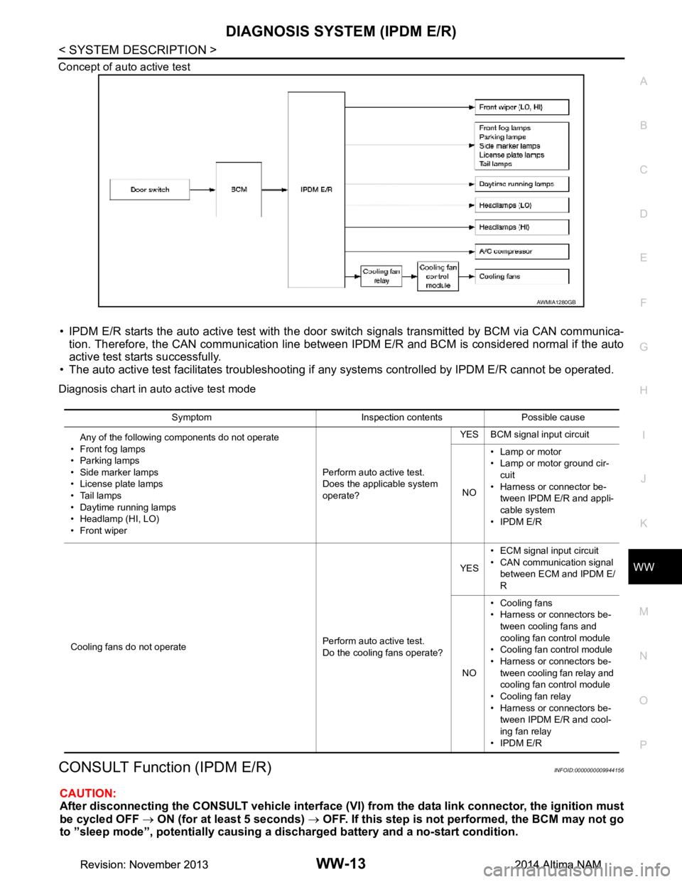
Concept of auto active test
• IPDM E/R starts the auto active test with the door
switch signals transmitted by BCM via CAN communica-
tion. Therefore, the CAN communication line between IPDM E/R and BCM is considered normal if the auto
active test starts successfully.
• The auto active test facilitates troubleshooting if any systems controlled by IPDM E/R cannot be operated.
Diagnosis chart in auto active test mode
CONSULT Function (IPDM E/R)INFOID:0000000009944156
CAUTION:
After disconnecting the CONSULT vehicle interface (VI) from the data link connector, the ignition must
be cycled OFF → ON (for at least 5 seconds) → OFF. If this step is not performed, the BCM may not go
to ”sleep mode”, potentiall y causing a discharged battery and a no-start condition.
AWMIA1280GB
Symptom Inspection contents Possible cause
Any of the following components do not operate
• Front fog lamps
•Parking lamps
• Side marker lamps
• License plate lamps
•Tail lamps
• Daytime running lamps
• Headlamp (HI, LO)
• Front wiper Perform auto active test.
Does the applicable system
operate? YES BCM signal input circuit
NO • Lamp or motor
• Lamp or motor ground cir-
cuit
• Harness or connector be- tween IPDM E/R and appli-
cable system
• IPDM E/R
Cooling fans do not operate Perform auto active test.
Do the cooling fans operate? YES
• ECM signal input circuit
• CAN communication signal between ECM and IPDM E/
R
NO • Cooling fans
• Harness or connectors be-
tween cooling fans and
cooling fan control module
• Cooling fan control module
• Harness or connectors be- tween cooling fan relay and
cooling fan control module
• Cooling fan relay
• Harness or connectors be- tween IPDM E/R and cool-
ing fan relay
• IPDM E/R
Revision: November 20132014 Altima NAMRevision: November 20132014 Altima NAM
Page 4749 of 4801

WW-14
< SYSTEM DESCRIPTION >
DIAGNOSIS SYSTEM (IPDM E/R)
APPLICATION ITEM
CONSULT performs the following functions via CAN communication with IPDM E/R.
ECU IDENTIFICATION
The IPDM E/R part number is displayed.
SELF DIAGNOSTIC RESULT
Refer to PCS-20, "DTC Index".
DATA MONITOR
Direct Diagnostic Mode Description
Ecu Identification The IPDM E/R part number is displayed.
Self Diagnostic Result The IPDM E/R self diagnostic results are displayed.
Data Monitor The IPDM E/R input/output data is displayed in real time.
Active Test The IPDM E/R activates outputs to test components.
CAN Diag Support Mntr The result of transmit/receive diagnosis of CAN communication is displayed.
Monitor Item [Unit] Main
Signals Description
MOTOR FAN REQ [%] ×Indicates cooling fan speed signal received from ECM on CAN communication
line
AC COMP REQ [On/Off] ×Indicates A/C compressor request signal received from ECM on CAN commu-
nication line
TAIL&CLR REQ [On/Off] ×Indicates position light request signal received from BCM on CAN communica-
tion line
HL LO REQ [On/Off] ×Indicates low beam request signal received from BCM on CAN communication
line
HL HI REQ [On/Off] ×Indicates high beam request signal received from BCM on CAN communication
line
FR FOG REQ [On/Off] ×Indicates front fog light request signal received from BCM on CAN communica-
tion line
FR WIP REQ [Stop/1LOW/Low/Hi] ×Indicates front wiper request signal received from BCM on CAN communication
line
WIP AUTO STOP [STOP P/ACT P] ×Indicates condition of front wiper auto stop signal
WIP PROT [Off/BLOCK] ×Indicates condition of front wiper fail-safe operation
IGN RLY1 -REQ [On/Off] Indicates ignition switch ON signal received from BCM on CAN communication
line
IGN RLY [On/Off] ×Indicates condition of ignition relay
PUSH SW [On/Off] Indicates condition of push-button ignition switch
INTER/NP SW [On/Off] Indicates condition of CVT shift position
ST RLY CONT [On/Off] Indicates starter relay status signal received from BCM on CAN communication
line
IHBT RLY -REQ [On/Off] Indicates starter control relay signal received from BCM on CAN communication
line
ST/INHI RLY [Off/ ST /INHI] Indicates condition of starter relay and starter control relay
DETENT SW [On/Off] Indicates condition of CVT shift selector (park position switch)
DTRL REQ [Off] Indicates daytime light request signal received from BCM on CAN communica-
tion line
HOOD SW [On/Off] Indicates condition of hood switch
THFT HRN REQ [On/Off] Indicates theft warning horn request signal received from BCM on CAN commu-
nication line
Revision: November 20132014 Altima NAMRevision: November 20132014 Altima NAM
Page 4750 of 4801
![NISSAN TEANA 2014 Service Manual
DIAGNOSIS SYSTEM (IPDM E/R)WW-15
< SYSTEM DESCRIPTION >
C
D E
F
G H
I
J
K
M A
B
WW
N
O P
ACTIVE TEST
CAN DIAG SUPPORT MNTR
Refer to LAN-15, "CAN Diagnostic Support Monitor".
HORN CHIRP [On/Off] I NISSAN TEANA 2014 Service Manual
DIAGNOSIS SYSTEM (IPDM E/R)WW-15
< SYSTEM DESCRIPTION >
C
D E
F
G H
I
J
K
M A
B
WW
N
O P
ACTIVE TEST
CAN DIAG SUPPORT MNTR
Refer to LAN-15, "CAN Diagnostic Support Monitor".
HORN CHIRP [On/Off] I](/img/5/57390/w960_57390-4749.png)
DIAGNOSIS SYSTEM (IPDM E/R)WW-15
< SYSTEM DESCRIPTION >
C
D E
F
G H
I
J
K
M A
B
WW
N
O P
ACTIVE TEST
CAN DIAG SUPPORT MNTR
Refer to LAN-15, "CAN Diagnostic Support Monitor".
HORN CHIRP [On/Off] Indicates horn reminder signal received from BCM on CAN communication line
HOOD SW 2 [On/Off] Indicates condition of hood switch 2 Monitor Item [Unit]
Main
Signals Description
Test item Description
HORN This test is able to check horn operation [On].
FRONT WIPER This test is able to check wiper motor operation [Hi/Lo/Off].
MOTOR FAN This test is able to check cooling fan operation [4/3/2/1].
EXTERNAL LAMPS This test is able to check external lamp operation [Fog/Hi/Lo/TAIL/Off].
Revision: November 20132014 Altima NAMRevision: November 20132014 Altima NAM