NISSAN TEANA 2014 Service Manual
Manufacturer: NISSAN, Model Year: 2014, Model line: TEANA, Model: NISSAN TEANA 2014Pages: 4801, PDF Size: 51.2 MB
Page 4781 of 4801
WW-46
< SYMPTOM DIAGNOSIS >
WIPER AND WASHER SYSTEM SYMPTOMS
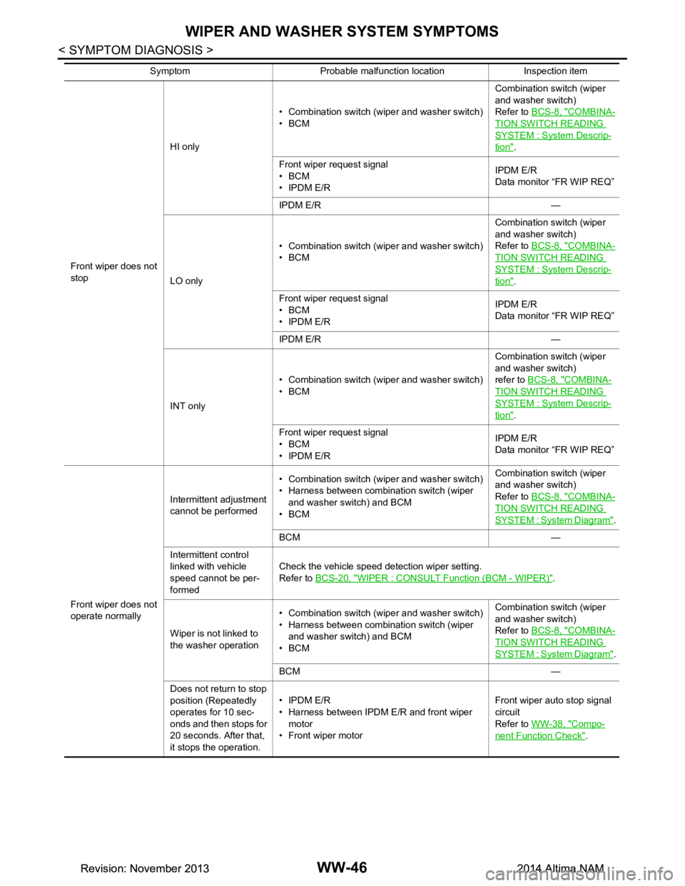
Front wiper does not
stop HI only
• Combination switch (wiper and washer switch)
•BCM Combination switch (wiper
and washer switch)
Refer to BCS-8, "COMBINA-
TION SWITCH READING
SYSTEM : System Descrip-
tion".
Front wiper request signal
•BCM
•IPDM E/R IPDM E/R
Data monitor “FR WIP REQ”
IPDM E/R —
LO only • Combination switch (wiper and washer switch)
•BCM Combination switch (wiper
and washer switch)
Refer to BCS-8, "COMBINA-
TION SWITCH READING
SYSTEM : System Descrip-
tion".
Front wiper request signal
•BCM
•IPDM E/R IPDM E/R
Data monitor “FR WIP REQ”
IPDM E/R —
INT only • Combination switch (wiper and washer switch)
•BCM Combination switch (wiper
and washer switch)
refer to BCS-8, "COMBINA-
TION SWITCH READING
SYSTEM : System Descrip-
tion".
Front wiper request signal
•BCM
•IPDM E/R IPDM E/R
Data monitor “FR WIP REQ”
Front wiper does not
operate normally Intermittent adjustment
cannot be performed • Combination switch (wiper and washer switch)
• Harness between combination switch (wiper and washer switch) and BCM
•BCM Combination switch (wiper
and washer switch)
Refer to BCS-8, "COMBINA-
TION SWITCH READING
SYSTEM : System Diagram".
BCM —
Intermittent control
linked with vehicle
speed cannot be per-
formed Check the vehicle speed detection wiper setting.
Refer to BCS-20, "WIPER : CONSULT Function (BCM - WIPER)"
.
Wiper is not linked to
the washer operation • Combination switch (wiper and washer switch)
• Harness between combination switch (wiper and washer switch) and BCM
•BCM Combination switch (wiper
and washer switch)
Refer to BCS-8, "COMBINA-
TION SWITCH READING
SYSTEM : System Diagram".
BCM —
Does not return to stop
position (Repeatedly
operates for 10 sec-
onds and then stops for
20 seconds. After that,
it stops the operation. •IPDM E/R
• Harness between IPDM E/R and front wiper motor
• Front wiper motor Front wiper auto stop signal
circuit
Refer to WW-38, "Compo-
nent Function Check".
Symptom Probable malfunction location Inspection item
Revision: November 20132014 Altima NAMRevision: November 20132014 Altima NAM
Page 4782 of 4801
WIPER AND WASHER SYSTEM SYMPTOMSWW-47
< SYMPTOM DIAGNOSIS >
C
D E
F
G H
I
J
K
M A
B
WW
N
O P
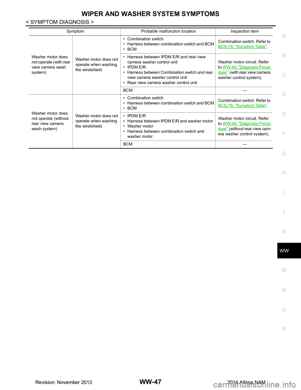
Washer motor does
not operate (with rear
view camera wash
system) Washer motor does not
operate when washing
the windshield. • Combination switch
• Harness between combination switch and BCM
•BCM Combination switch. Refer to
BCS-79, "Symptom Table"
.
• Harness between IPDM E/R and rear view camera washer control unit
• IPDM E/R
• Harness between Combination switch and rear view camera washer control unit
• Rear view camera washer control unit Washer motor circuit. Refer
to WW-40, "Diagnosis Proce-
dure" (with rear view camera
washer control system).
BCM —
Washer motor does
not operate (without
rear view camera
wash system) Washer motor does not
operate when washing
the windshield. • Combination switch
• Harness between combination switch and BCM
•BCM Combination switch. Refer to
BCS-79, "Symptom Table"
.
• IPDM E/R
• Harness between IPDM E/R and washer motor
• Washer motor
• Harness between combination switch and washer motor Washer motor circuit. Refer
to WW-40, "Diagnosis Proce-
dure" (without rear view cam-
era washer control system).
BCM —
Symptom Probable malfunction location Inspection item
Revision: November 20132014 Altima NAMRevision: November 20132014 Altima NAM
Page 4783 of 4801
WW-48
< SYMPTOM DIAGNOSIS >
FRONT WIPER DOES NOT OPERATE
FRONT WIPER DOES NOT OPERATE
DescriptionINFOID:0000000009464625
The front wiper does not operate under any operation conditions
Diagnosis ProcedureINFOID:0000000009464626
Regarding Wiring Diagram information, refer to WW-23, "Wiring Diagram - With Rear View Camera Washer
Control System".
1. CHECK WIPER RELAY OPERATION
IPDM E/R AUTO ACTIVE TEST
1. Start IPDM E/R auto active test. Refer to PCS-8, "Diagnosis Description"
.
2. Check that the front wiper operates at the LO/HI operation.
CONSULT ACTIVE TEST
1. Select FRONT WIPER of IPDM E/R active test item.
2. While operating the test item, check that front wiper LO/HI operation and OFF.
is the inspection result normal?
YES >> GO TO 5.
NO >> GO TO 2.
2. CHECK FRONT WIPER MOTOR FUSE
1. Turn the ignition switch OFF.
2. Check that the front wiper motor fuse 30A (No. 41, located in the IPDM E/R) is not blown.
Is the fuse blown?
YES >> Replace the fuse after repairing the affected circuit.
NO >> GO TO 3.
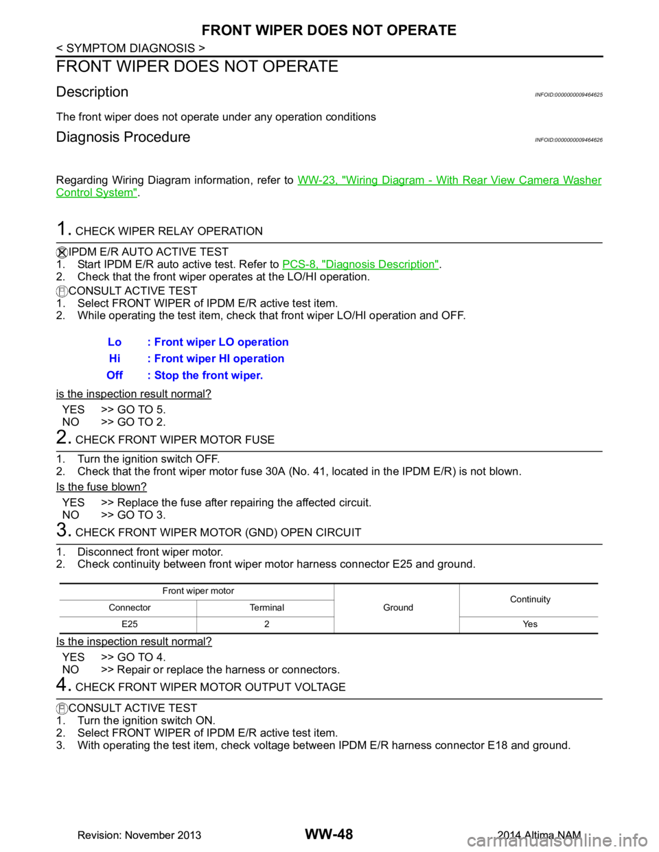
3. CHECK FRONT WIPER MOTOR (GND) OPEN CIRCUIT
1. Disconnect front wiper motor.
2. Check continuity between front wiper motor harness connector E25 and ground.
Is the inspection result normal?
YES >> GO TO 4.
NO >> Repair or replace the harness or connectors.
4. CHECK FRONT WIPER MOTOR OUTPUT VOLTAGE
CONSULT ACTIVE TEST
1. Turn the ignition switch ON.
2. Select FRONT WIPER of IPDM E/R active test item.
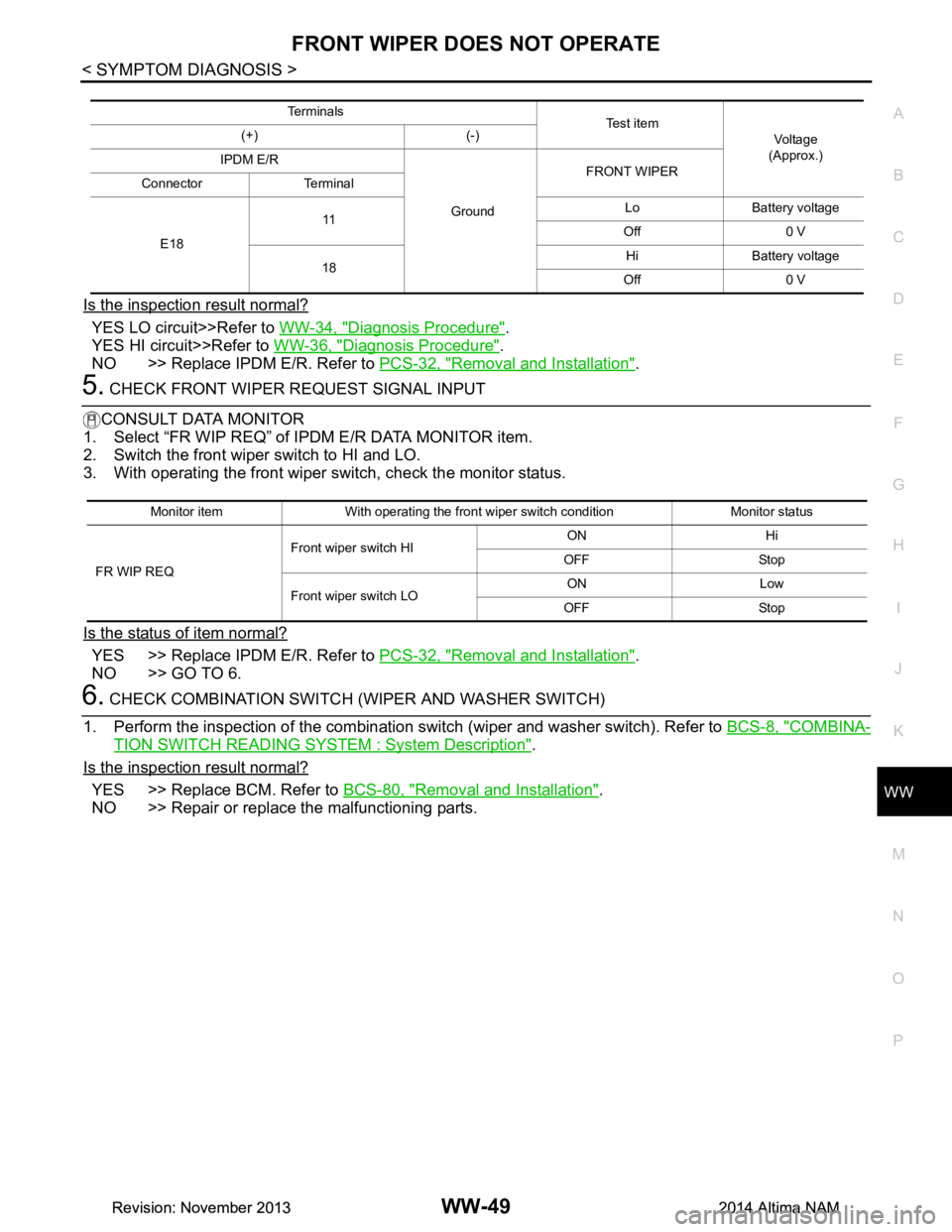
3. With operating the test item, check volt age between IPDM E/R harness connector E18 and ground.
Lo : Front wiper LO operation
Hi : Front wiper HI operation
Off : Stop the front wiper.
Front wiper motor
GroundContinuity
Connector Terminal
E25 2 Yes
Revision: November 20132014 Altima NAMRevision: November 20132014 Altima NAM
Page 4784 of 4801
FRONT WIPER DOES NOT OPERATEWW-49
< SYMPTOM DIAGNOSIS >
C
D E
F
G H
I
J
K
M A
B
WW
N
O P
Is the inspection result normal?
YES LO circuit>>Refer to WW-34, "Diagnosis Procedure".
YES HI circuit>>Refer to WW-36, "Diagnosis Procedure"
.
NO >> Replace IPDM E/R. Refer to PCS-32, "Removal and Installation"
.
5. CHECK FRONT WIPER REQUEST SIGNAL INPUT
CONSULT DATA MONITOR
1. Select “FR WIP REQ” of IPDM E/R DATA MONITOR item.
2. Switch the front wiper switch to HI and LO.
3. With operating the front wiper switch, check the monitor status.
Is the status of item normal?
YES >> Replace IPDM E/R. Refer to PCS-32, "Removal and Installation".
NO >> GO TO 6.
6. CHECK COMBINATION SWITCH (WIPER AND WASHER SWITCH)
1. Perform the inspection of the combination s witch (wiper and washer switch). Refer to BCS-8, "COMBINA-
TION SWITCH READING SYSTEM : System Description".
Is the inspection result normal?
YES >> Replace BCM. Refer to BCS-80, "Removal and Installation".
NO >> Repair or replace the malfunctioning parts.
Te r m i n a l s Te s t i t e m
Voltag e
(Approx.)
(+) (-)
IPDM E/R
GroundFRONT WIPER
Connector Terminal
E18 11
Lo Battery voltage
Off 0 V
18 Hi Battery voltage
Off 0 V
Monitor item With operating the front wiper switch condition Monitor status
FR WIP REQ Front wiper switch HI
ON Hi
OFF Stop
Front wiper switch LO ON Low
OFF Stop
Revision: November 20132014 Altima NAMRevision: November 20132014 Altima NAM
Page 4785 of 4801

WW-50
< SYMPTOM DIAGNOSIS >
NORMAL OPERATING CONDITION
NORMAL OPERATING CONDITION
DescriptionINFOID:0000000009464627
FRONT WIPER MOTOR PROTECTION FUNCTION
• IPDM E/R may stop the front wiper to protect the front wiper motor if any obstruction (operation resistance)
such as a large amount of snow is detected during the front wiper operation.
• At that time turn OFF the front wiper and remove t he foreign object. Then wait for approximately 20 seconds
or more and reactivate the front wiper. The wiper will operate normally.
Revision: November 20132014 Altima NAMRevision: November 20132014 Altima NAM
Page 4786 of 4801
WASHER TANKWW-51
< REMOVAL AND INSTALLATION >
C
D E
F
G H
I
J
K
M A
B
WW
N
O P
REMOVAL AND INSTALLATION
WASHER TANK
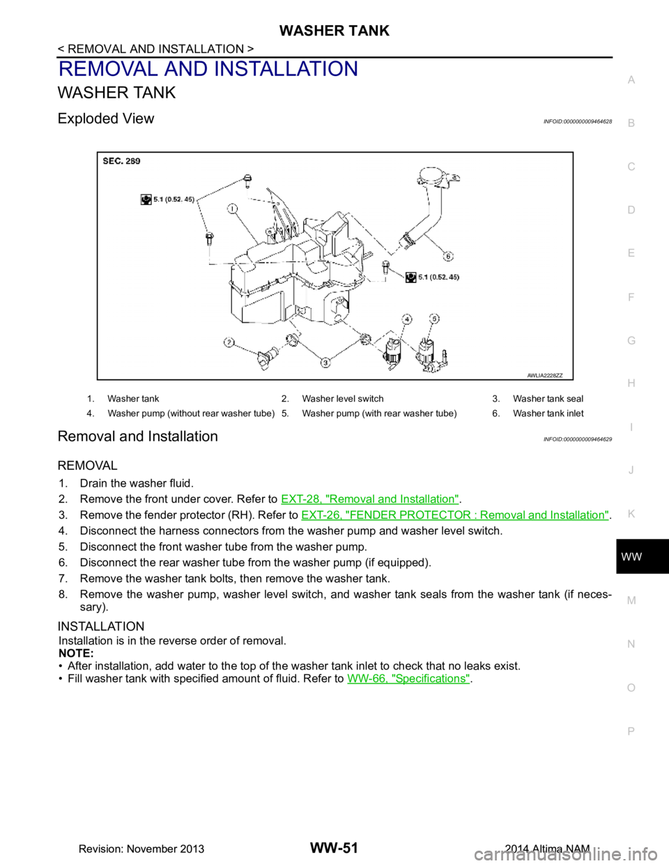
Exploded ViewINFOID:0000000009464628
Removal and InstallationINFOID:0000000009464629
REMOVAL
1. Drain the washer fluid.
2. Remove the front under cover. Refer to EXT-28, "Removal and Installation"
.
3. Remove the fender protector (RH). Refer to EXT-26, "FENDER PROTECTOR : Removal and Installation"
.
4. Disconnect the harness connectors from the washer pump and washer level switch.
5. Disconnect the front washer tube from the washer pump.
6. Disconnect the rear washer tube from the washer pump (if equipped).
7. Remove the washer tank bolts, then remove the washer tank.
8. Remove the washer pump, washer level switch, and wa sher tank seals from the washer tank (if neces-
sary).
INSTALLATION
Installation is in the reverse order of removal.
NOTE:
• After installation, add water to the top of the washer tank inlet to check that no leaks exist.
• Fill washer tank with specified amount of fluid. Refer to WW-66, "Specifications"
.
1. Washer tank 2. Washer level switch 3. Washer tank seal
4. Washer pump (without rear washer tube) 5. Washer pump (with rear washer tube) 6. Washer tank inlet
AWLIA2228ZZ
Revision: November 20132014 Altima NAMRevision: November 20132014 Altima NAM
Page 4787 of 4801
WW-52
< REMOVAL AND INSTALLATION >
WASHER PUMP
WASHER PUMP
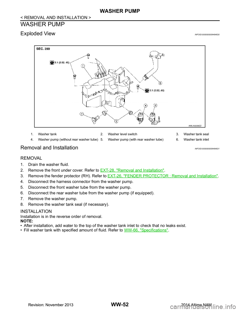
Exploded ViewINFOID:0000000009464630
Removal and InstallationINFOID:0000000009464631
REMOVAL
1. Drain the washer fluid.
2. Remove the front under cover. Refer to EXT-28, "Removal and Installation"
.
3. Remove the fender protector (RH). Refer to EXT-26, "FENDER PROTECTOR : Removal and Installation"
.
4. Disconnect the harness connecto r from the washer pump.
5. Disconnect the front washer tube from the washer pump.
6. Disconnect the rear washer tube from the washer pump (if equipped).
7. Remove the washer pump.
8. Remove the washer tank seal (if necessary).
INSTALLATION
Installation is in the reverse order of removal.
NOTE:
• After installation, add water to the top of the washer tank inlet to check that no leaks exist.
• Fill washer tank with specified amount of fluid. Refer to WW-66, "Specifications"
.
1. Washer tank 2. Washer level switch 3. Washer tank seal
4. Washer pump (without rear washer tube) 5. Washer pump (with rear washer tube) 6. Washer tank inlet
AWLIA2228ZZ
Revision: November 20132014 Altima NAMRevision: November 20132014 Altima NAM
Page 4788 of 4801
WASHER LEVEL SWITCHWW-53
< REMOVAL AND INSTALLATION >
C
D E
F
G H
I
J
K
M A
B
WW
N
O P
WASHER LEVEL SWITCH
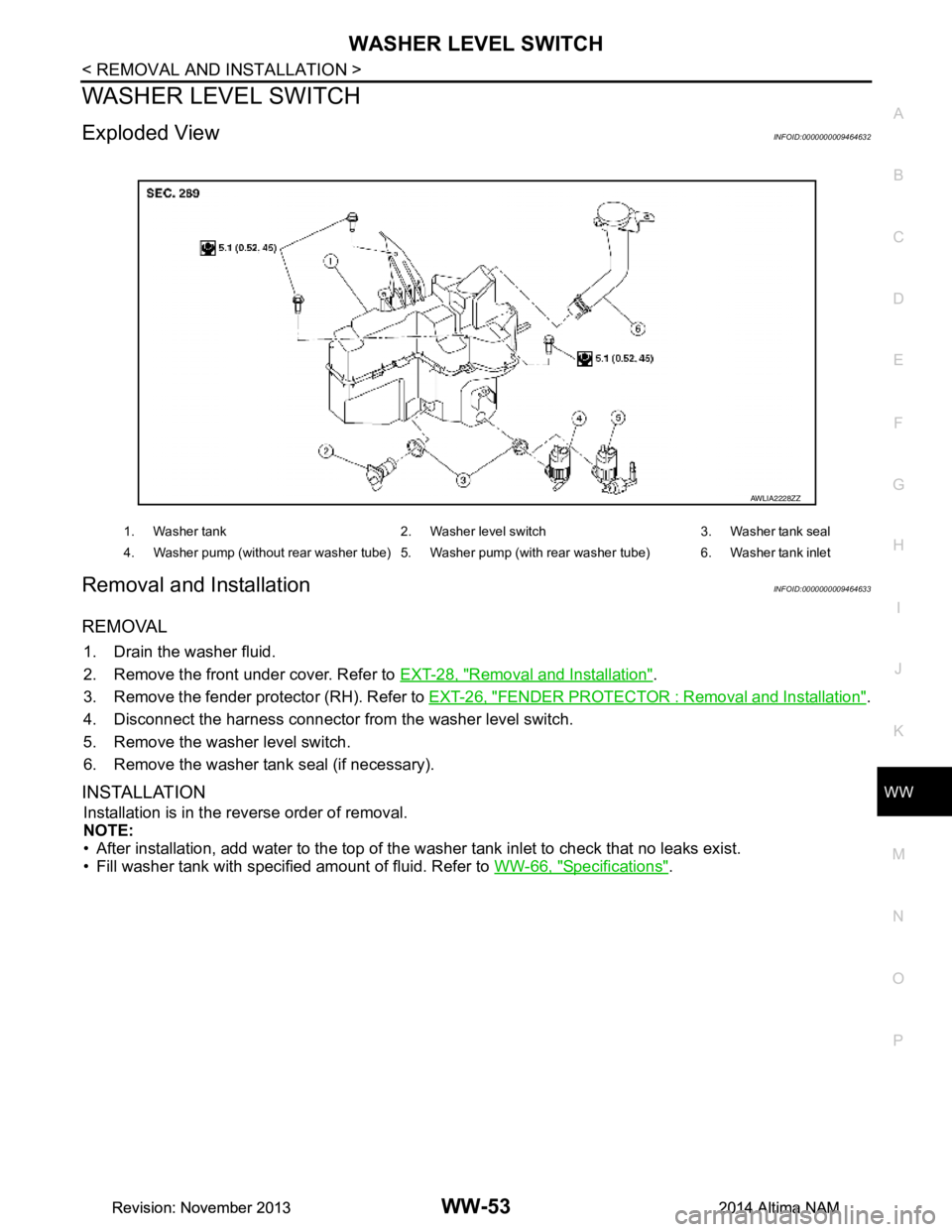
Exploded ViewINFOID:0000000009464632
Removal and InstallationINFOID:0000000009464633
REMOVAL
1. Drain the washer fluid.
2. Remove the front under cover. Refer to EXT-28, "Removal and Installation"
.
3. Remove the fender protector (RH). Refer to EXT-26, "FENDER PROTECTOR : Removal and Installation"
.
4. Disconnect the harness connector from the washer level switch.
5. Remove the washer level switch.
6. Remove the washer tank seal (if necessary).
INSTALLATION
Installation is in the reverse order of removal.
NOTE:
• After installation, add water to the top of the washer tank inlet to check that no leaks exist.
• Fill washer tank with specified amount of fluid. Refer to WW-66, "Specifications"
.
1. Washer tank 2. Washer level switch 3. Washer tank seal
4. Washer pump (without rear washer tube) 5. Washer pump (with rear washer tube) 6. Washer tank inlet
AWLIA2228ZZ
Revision: November 20132014 Altima NAMRevision: November 20132014 Altima NAM
Page 4789 of 4801
WW-54
< REMOVAL AND INSTALLATION >
WASHER NOZZLE & TUBE
WASHER NOZZLE & TUBE
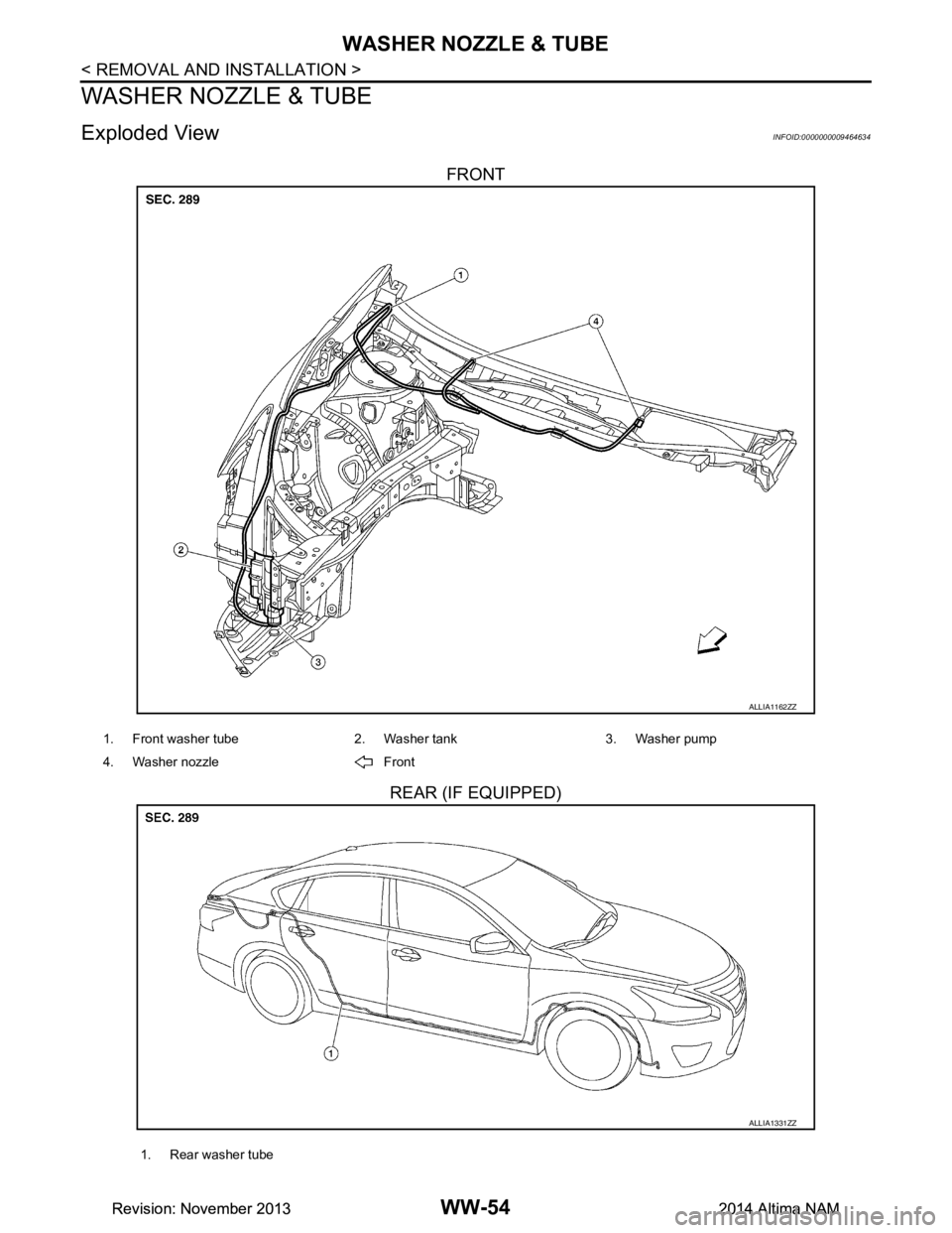
Exploded ViewINFOID:0000000009464634
FRONT
REAR (IF EQUIPPED)
ALLIA1162ZZ
1. Front washer tube 2. Washer tank 3. Washer pump
4. Washer nozzle Front
ALLIA1331ZZ
1. Rear washer tube
Revision: November 20132014 Altima NAMRevision: November 20132014 Altima NAM
Page 4790 of 4801
WASHER NOZZLE & TUBEWW-55
< REMOVAL AND INSTALLATION >
C
D E
F
G H
I
J
K
M A
B
WW
N
O P
WASHER NOZZLE
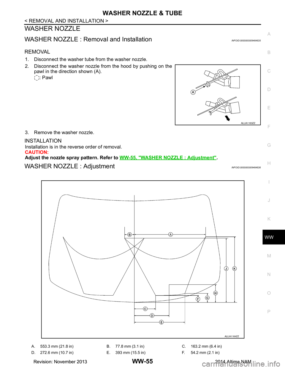
WASHER NOZZLE : Removal and InstallationINFOID:0000000009464635
REMOVAL
1. Disconnect the washer tube from the washer nozzle.
2. Disconnect the washer nozzle from the hood by pushing on the pawl in the direction shown (A).
: Pawl
3. Remove the washer nozzle.
INSTALLATION
Installation is in the reverse order of removal.
CAUTION:
Adjust the nozzle spray pattern. Refer to WW-55, "WASHER NOZZLE : Adjustment"
.
WASHER NOZZLE : AdjustmentINFOID:0000000009464636
ALLIA1163ZZ
A. 553.3 mm (21.8 in) B. 77.8 mm (3.1 in) C. 163.2 mm (6.4 in)
D. 272.6 mm (10.7 in) E. 393 mm (15.5 in) F. 54.2 mm (2.1 in)
ALLIA1164ZZ
Revision: November 20132014 Altima NAMRevision: November 20132014 Altima NAM