NISSAN TEANA 2014 Service Manual
Manufacturer: NISSAN, Model Year: 2014, Model line: TEANA, Model: NISSAN TEANA 2014Pages: 4801, PDF Size: 51.2 MB
Page 771 of 4801

DLK-3
C
D E
F
G H
I
J
L
M A
B
DLK
N
O P
PASSENGER SIDE : Diagnosis Procedure (With
LH and RH Anti-Pinch) ........................................ ..
106
PASSENGER SIDE : Diagnosis Procedure (With
LH Anti-Pinch Only) ............................................. ..
107
OUTSIDE KEY ANTENNA (PASSENGER
SIDE) .............................................................. ..
109
Component Function Check ................................ ..109
Diagnosis Procedure .............................................109
OUTSIDE KEY ANTENNA (DRIVER SIDE) .....111
Component Function Check ................................ ..111
Diagnosis Procedure .............................................111
OUTSIDE KEY ANTENNA (REAR BUMPER) ..113
Component Function Check ................................ ..113
Diagnosis Procedure .............................................113
KEY CYLINDER SWITCH ................................115
Description .......................................................... ..115
Component Function Check ..................................115
Diagnosis Procedure (With LH and RH Anti-Pinch)
..
115
Diagnosis Procedure (With LH Anti-Pinch Only) ...116
Component Inspection ..........................................117
UNLOCK SENSOR ..........................................119
Description .......................................................... ..119
Component Function Check ................................119
Diagnosis Procedure .............................................119
Component Inspection ..........................................120
TRUNK LID OPENER SWITCH .......................122
Description .......................................................... ..122
Component Function Check ................................122
Diagnosis Procedure .............................................122
Component Inspection ..........................................123
TRUNK LID OPENER CANCEL SWITCH .......124
Description .......................................................... ..124
Component Function Check ................................124
Diagnosis Procedure .............................................124
Component Inspection ..........................................125
TRUNK LAMP SWITCH ...................................126
Description .......................................................... ..126
Component Function Check ................................126
Diagnosis Procedure .............................................126
Component Inspection ..........................................127
DOOR REQUEST SWITCH ..............................129
Description .......................................................... ..129
Component Function Check ................................129
Diagnosis Procedure .............................................129
Component Inspection ..........................................131
TRUNK OPENER REQUEST SWITCH ............132
Description .......................................................... ..132
Component Function Check ................................132
Diagnosis Procedure .............................................132
Component Inspection ..........................................133
DOOR LOCK ACTUATOR ..............................135
DRIVER SIDE ......................................................... ..135
DRIVER SIDE : Description ...................................135
DRIVER SIDE : Component Function Check ......135
DRIVER SIDE : Diagnosis Procedure ...................135
PASSENGER SIDE ..................................................136
PASSENGER SIDE : Descript ion ..........................136
PASSENGER SIDE :
Component Function Check .............................. ..
136
PASSENGER SIDE : Diagnosis Procedure ..........136
REAR LH ................................................................ ..137
REAR LH : Description ..........................................137
REAR LH : Component Function Check ..............137
REAR LH : Diagnosis Procedure ...........................137
REAR RH ............................................................... ..138
REAR RH : Description .........................................138
REAR RH : Component Function Check .............138
REAR RH : Diagnosis Procedure ..........................138
TRUNK LID OPENER ACTUATOR ................140
Description .............................................................140
Component Function Check ................................140
Diagnosis Procedure .............................................140
INTELLIGENT KEY WARNING BUZZER .......142
Description .............................................................142
Component Function Check ................................142
Diagnosis Procedure .............................................142
Component Inspection ...........................................143
REMOTE KEYLESS ENTRY RECEIVER .......144
Description .............................................................144
Component Function Check ................................144
Diagnosis Procedure .............................................144
INTELLIGENT KEY BATTERY AND FUNC-
TION ................................................................
146
Description ........................................................... ..146
Component Function Check ................................146
Diagnosis Procedure .............................................146
WARNING CHIME FUNCTION .......................148
Description .............................................................148
Component Function Check ................................148
Diagnosis Procedure .............................................148
HAZARD FUNCTION ......................................149
Description .............................................................149
Component Function Check ................................149
Diagnosis Procedure .............................................149
HOMELINK UNIVERSAL TRANSCEIVER .....150
Description .............................................................150
Component Function Check ................................150
Diagnosis Procedure .............................................150
SYMPTOM DIAGNOSIS ............................152
Revision: November 20132014 Altima NAMRevision: November 20132014 Altima NAM
Page 772 of 4801

DLK-4
INTELLIGENT KEY SYSTEM SYMPTOMS ....152
Symptom Table ................................................... ..152
DOOR LOCK FUNCTION SYMPTOMS ..........153
DOOR LOCK AND UNLOCK SWITCH ................. ..153
DOOR LOCK AND UNLOCK SWITCH : Symptom
Table .................................................................... ..
153
DOOR REQUEST SWITCH ................................... ..153
DOOR REQUEST SWITCH : Symptom Table ......153
INTELLIGENT KEY ................................................ ..154
INTELLIGENT KEY : Symptom Table ...................154
TRUNK OPEN FUNCTION SYMPTOMS ....... .156
TRUNK LID OPENER SWITCH ............................. ..156
TRUNK LID OPENER SWITCH : Symptom Table ..156
TRUNK REQUEST SWITCH .................................. ..156
TRUNK REQUEST SWITCH : Symptom Table .....156
INTELLIGENT KEY ................................................ ..156
INTELLIGENT KEY : Symptom Table ...................156
WARNING FUNCTION SYMPTOMS .............. .158
Symptom Table ................................................... ..158
KEY REMINDER FUNCTION SYMPTOMS .....160
Symptom Table ................................................... ..160
HAZARD FUNCTION .......................................161
Symptom Table ................................................... ..161
HORN FUNCTION ...........................................162
Symptom Table ................................................... ..162
INTEGRATED HOMELINK TRANSMITTER ...163
Symptom Table ................................................... ..163
SQUEAK AND RATTLE TROUBLE DIAG-
NOSES ......................... ....................................
164
Work Flow ............................................................ ..164
Generic Squeak and Rattle Troubleshooting .........165
Diagnostic Worksheet ............................................168
REMOVAL AND INSTALLATION ..............170
HOOD .............................................................. .170
HOOD ASSEMBLY ................................................ ..170
HOOD ASSEMBLY : Exploded View ................... ..170
HOOD ASSEMBLY : Removal and Installation .....170
HOOD ASSEMBLY : Adjustme nt ........................ ..172
HOOD HINGE ......................................................... ..174
HOOD HINGE : Removal and Installation .............174
HOOD SUPPORT ROD .......................................... ..175
HOOD SUPPORT ROD : Removal and Installa-
tion ....................................................................... ..
175
HOOD LOCK CONTROL ....................................... ..175
HOOD LOCK CONTROL : Component Parts Lo-
cation ................................................................... .
175
HOOD LOCK CONTROL : Removal and Installa-
tion ....................................................................... .
176
RADIATOR CORE SUPPORT .........................179
Removal and Installation .......................................179
FRONT FENDER ............................................ ..181
Exploded View ..................................................... .181
Removal and Installation .......................................181
Adjustment ........................................................... .182
FRONT DOOR ..................................................184
DOOR ASSEMBLY .................................................184
DOOR ASSEMBLY : Removal and Installation ....184
DOOR ASSEMBLY : Adjustme nt ..........................186
DOOR STRIKER .................................................... .188
DOOR STRIKER : Removal and Installation ........188
DOOR HINGE ......................................................... .188
DOOR HINGE : Removal and Installation ............188
DOOR CHECK LINK .............................................. .189
DOOR CHECK LINK : Removal and Installation ..189
REAR DOOR ....................................................190
DOOR ASSEMBLY .................................................190
DOOR ASSEMBLY : Removal and Installation ....190
DOOR ASSEMBLY : Adjustme nt ..........................191
DOOR STRIKER .................................................... .194
DOOR STRIKER : Removal and Installation ........194
DOOR HINGE ......................................................... .194
DOOR HINGE : Removal and Installation ............194
DOOR CHECK LINK .............................................. .195
DOOR CHECK LINK : Removal and Installation ..195
DOOR HANDLE ...............................................197
FRONT DOOR HANDLE ........................................ .197
FRONT DOOR HANDLE : Exploded View ...........197
FRONT DOOR HANDLE : Removal and Installa-
tion - Inside Handle .............................................. .
197
FRONT DOOR HANDLE : Removal and Installa-
tion - Outside Handle ........................................... .
198
REAR DOOR HANDLE .......................................... .200
REAR DOOR HANDLE : Exploded View ..............200
REAR DOOR HANDLE : Removal and Installation
- Inside Handle ..................................................... .
200
REAR DOOR HANDLE : Removal and Installation
- Outside Handle .................................................. .
201
DOOR LOCK ....................................................203
FRONT DOOR LOCK ............................................. .203
FRONT DOOR LOCK : Exploded View ................203
FRONT DOOR LOCK : Removal and Installation .203
Revision: November 20132014 Altima NAMRevision: November 20132014 Altima NAM
Page 773 of 4801

DLK-5
C
D E
F
G H
I
J
L
M A
B
DLK
N
O P
REAR DOOR LOCK ..............................................
..
204
REAR DOOR LOCK : Exploded View ...................204
REAR DOOR LOCK : Removal and Installation ...205
TRUNK LID ..................................................... ..206
TRUNK LID ASSEMBLY ...... ...................................206
TRUNK LID ASSEMBLY : Exploded View .......... ..206
TRUNK LID ASSEMBLY : Removal and Installa-
tion ...................................................................... ..
206
TRUNK LID ASSEMBLY : Adjustment ................ ..208
TRUNK LID HINGE ............................................... ..209
TRUNK LID HINGE : Removal and Installation ....209
TORSION BAR ...................................................... ..210
TORSION BAR : Removal and Installation ...........210
TRUNK LAMP SWITCH AND TRUNK RELEASE
SOLENOID ............................................................ ..
210
TRUNK LAMP SWITCH AND TRUNK RELEASE
SOLENOID : Removal and Installation .................
210
EMERGENCY LEVER ........................................... ..211
EMERGENCY LEVER : Removal and Installation ..211
TRUNK LID STRIKER ........................................... ..211
TRUNK LID STRIKER : Removal and Installation ..211
FUEL FILLER LID OPENER ............................213
Exploded View .................................................... ..213
FUEL FILLER LID ................................................. ..213
FUEL FILLER LID : Removal and Installation .......213
FUEL FILLER OPENER CABLE ........................... ..214
FUEL FILLER OPENER CABLE : Removal and
Installation ........................................................... ..
214
FUEL FILLER LID LOCK ...................................... ..215
FUEL FILLER LID LOCK : Removal and Installa-
tion ...................................................................... ..
215
KEY CYLINDER ...............................................217
GLOVE BOX LID KEY CYLINDER ....................... ..217
GLOVE BOX LID KEY CYLINDER : Removal and
Installation ........................................................... ..
217
SEATBACK LOCK KEY CYLINDER .................... ..218
SEATBACK LOCK KEY CYLINDER : Removal
and Installation .................................................... ..
218
DOOR SWITCH ................................................219
Removal and Installation .......................................219
INSIDE KEY ANTENNA ..................................220
CONSOLE .............................................................. ..220
CONSOLE : Removal and Installation ...................220
LUGGAGE ROOM ................................................. ..220
LUGGAGE ROOM : Removal and Installation ......220
OUTSIDE KEY ANTENNA ..............................221
DRIVER SIDE ......................................................... ..221
DRIVER SIDE : Removal and Installation .............221
PASSENGER SIDE ..................................................221
PASSENGER SIDE : Removal and Installation .. ..221
REAR BUMPER ..................................................... ..221
REAR BUMPER : Removal and Installation ..........221
DOOR REQUEST SWITCH ............................222
DRIVER SIDE ......................................................... ..222
DRIVER SIDE : Removal and Installation .............222
PASSENGER SIDE ..................................................222
PASSENGER SIDE : Removal and Installation .. ..222
INTELLIGENT KEY WARNING BUZZER .......223
Removal and Installation .......................................223
REMOTE KEYLESS ENTRY RECEIVER .......224
Removal and Installation .......................................224
INTELLIGENT KEY BATTERY .......................225
Removal and Installation .......................................225
TRUNK LID OPENER CANCEL SWITCH ......226
Removal and Installation .......................................226
TRUNK LID OPENER SWITCH ......................227
Removal and Installation .......................................227
TRUNK OPENER REQUEST SWITCH ..........228
Removal and Installation .......................................228
UNIT DISASSEMBLY AND ASSEMBLY ..229
FRONT DOOR .................................................229
Exploded View ..................................................... ..229
Disassembly and Assembly ...................................229
REAR DOOR ...................................................231
Exploded View .......................................................231
Disassembly and Assembly ...................................231
Revision: November 20132014 Altima NAMRevision: November 20132014 Altima NAM
Page 774 of 4801
DLK-6
< PRECAUTION >
PRECAUTIONS
PRECAUTION
PRECAUTIONS
Precaution for Supplemental Restraint System (SRS) "AIR BAG" and "SEAT BELT
PRE-TENSIONER"
INFOID:0000000009951560
The Supplemental Restraint System such as “A IR BAG” and “SEAT BELT PRE-TENSIONER”, used along
with a front seat belt, helps to reduce the risk or severi ty of injury to the driver and front passenger for certain
types of collision. Information necessary to service the system safely is included in the SR and SB section of
this Service Manual.
WARNING:
• To avoid rendering the SRS inopera tive, which could increase the risk of personal injury or death in
the event of a collision which would result in air bag inflation, all maintenance must be performed by
an authorized NISS AN/INFINITI dealer.
• Improper maintenance, including in correct removal and installation of the SRS, can lead to personal
injury caused by unintent ional activation of the system. For re moval of Spiral Cable and Air Bag
Module, see the SR section.
• Do not use electrical test equipmen t on any circuit related to the SRS unless instructed to in this
Service Manual. SRS wiring harn esses can be identified by yellow and/or orange harnesses or har-
ness connectors.
PRECAUTIONS WHEN USING POWER TOOLS (AIR OR ELECTRIC) AND HAMMERS
WARNING:
• When working near the Airbag Diagnosis Sensor Unit or other Airbag System sensors with the Igni-
tion ON or engine running, DO NOT use air or electri c power tools or strike near the sensor(s) with a
hammer. Heavy vibration could activate the sensor( s) and deploy the air bag(s), possibly causing
serious injury.
• When using air or electric power tools or hammers , always switch the Ignition OFF, disconnect the
battery and wait at least three minutes before performing any service.
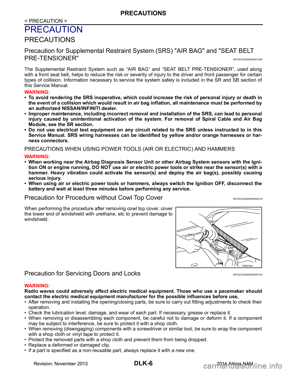
Precaution for Procedure without Cowl Top CoverINFOID:0000000009663378
When performing the procedure after removing cowl top cover, cover
the lower end of windshield with urethane, etc to prevent damage to
windshield.
Precaution for Servicing Doors and LocksINFOID:0000000009461762
WARNING:
Radio waves could adversely affect electric medical equipment. Those who use a pacemaker should
contact the electric medical eq uipment manufacturer for the possible influences before use,
• After removing and installing the opening/closing parts, be sure to carry out fitting adjustments to check their
operation.
• Check the lubrication level, damage, and wear of each part. If necessary, grease or replace it.
• When removing or disassembling each component, be careful not to damage or deform it. If a component may be subject to interference, be sure to protect it with a shop cloth.
• When removing (disengaging) components with a screwdriver or similar tool, be sure to wrap the component
with a shop cloth or vinyl tape to protect it.
• Protect the removed parts with a s hop cloth and prevent them from being dropped.
• Replace a deformed or damaged clip.
• If a part is specified as a non-reusable part, always replace it with a new one.
PIIB3706J
Revision: November 20132014 Altima NAMRevision: November 20132014 Altima NAM
Page 775 of 4801

PRECAUTIONSDLK-7
< PRECAUTION >
C
D E
F
G H
I
J
L
M A
B
DLK
N
O P
• Be sure to tighten bolts and nuts securely to the specified torque.
• After installation is complete, be sure to check that each part works properly.
• Follow the steps below to clean components:
- Water soluble dirt:
• Dip a soft cloth into lukewarm water, wring the water out of the cloth and wipe the dirty area.
• Then rub with a soft, dry cloth.
-Oily dirt:
• Dip a soft cloth into lukewarm water with mild detergent (concentration: within 2 to 3%) and wipe the dirty area.
• Then dip a cloth into fresh water, wring the water out of the cloth and wipe the detergent off.
• Then rub with a soft, dry cloth.
- Do not use organic solvent such as thinner, benzene, alcohol or gasoline.
- For genuine leather seats, use a genuine leather seat cleaner.
Revision: November 20132014 Altima NAMRevision: November 20132014 Altima NAM
Page 776 of 4801
DLK-8
< PREPARATION >
PREPARATION
PREPARATION
PREPARATION
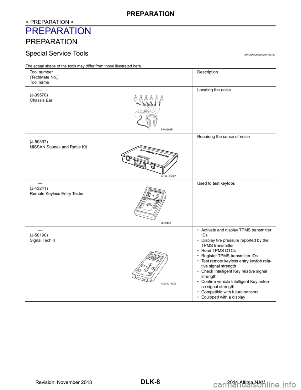
Special Service ToolsINFOID:0000000009461763
The actual shape of the tools may differ from those illustrated here.
Tool number
(TechMate No.)
Tool name Description
—
(J-39570)
Chassis Ear Locating the noise
—
(J-50397)
NISSAN Squeak and Rattle Kit Repairing the cause of noise
—
(J-43241)
Remote Keyless Entry Tester Used to test keyfobs
—
(J-50190)
Signal Tech II • Activate and display TPMS transmitter
IDs
• Display tire pressu re reported by the
TPMS transmitter
• Read TPMS DTCs
• Register TPMS transmitter IDs
• Test remote keyless entry keyfob rela- tive signal strength
• Check Intelligent Key relative signal strength
• Confirm vehicle Intelligent Key anten-
na signal strength
• Compatible with future sensors
• Equipped with a display
SIIA0993E
ALJIA1232ZZ
LEL946A
ALEIA0131ZZ
Revision: November 20132014 Altima NAMRevision: November 20132014 Altima NAM
Page 777 of 4801
PREPARATIONDLK-9
< PREPARATION >
C
D E
F
G H
I
J
L
M A
B
DLK
N
O P
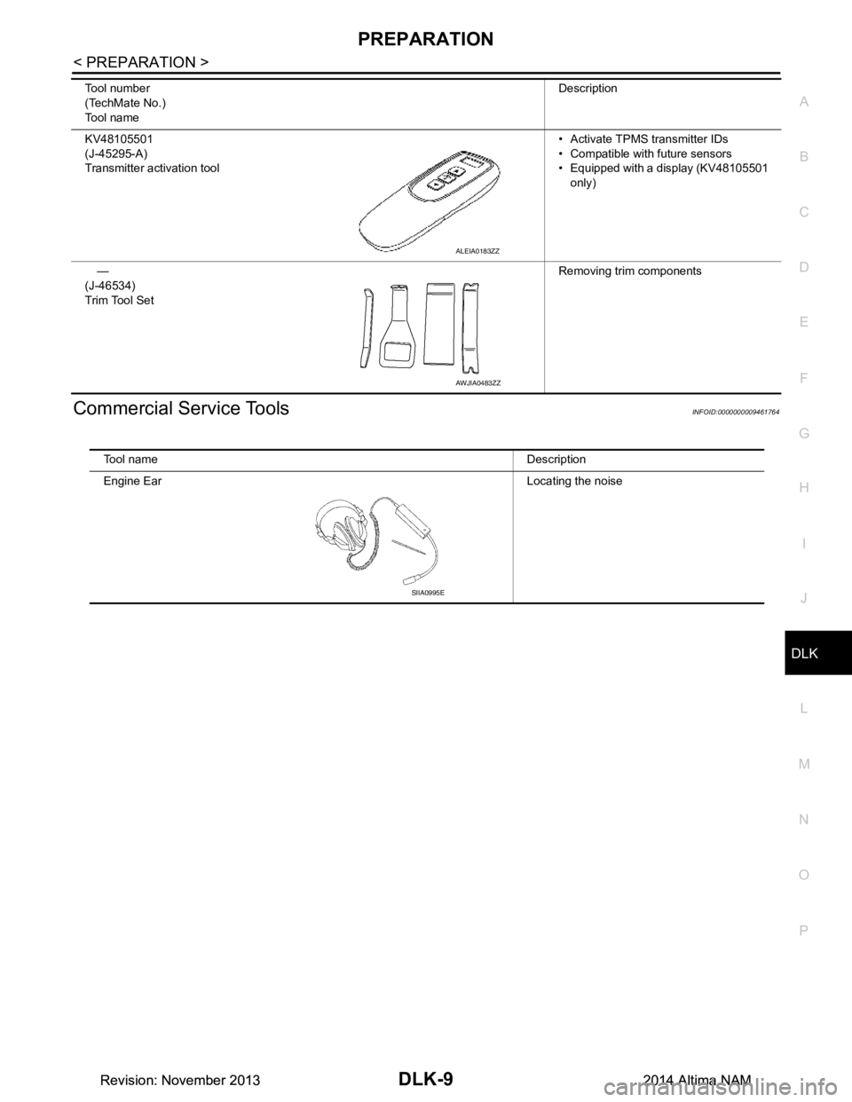
Commercial Service ToolsINFOID:0000000009461764
KV48105501
(J-45295-A)
Transmitter activation tool • Activate TPMS transmitter IDs
• Compatible with future sensors
• Equipped with a display (KV48105501
only)
—
(J-46534)
Trim Tool Set Removing trim components
Tool number
(TechMate No.)
Tool name Description
ALEIA0183ZZ
AWJIA0483ZZ
Tool name Description
Engine Ear Locating the noise
SIIA0995E
Revision: November 20132014 Altima NAMRevision: November 20132014 Altima NAM
Page 778 of 4801
DLK-10
< PREPARATION >
CLIP LIST
CLIP LIST
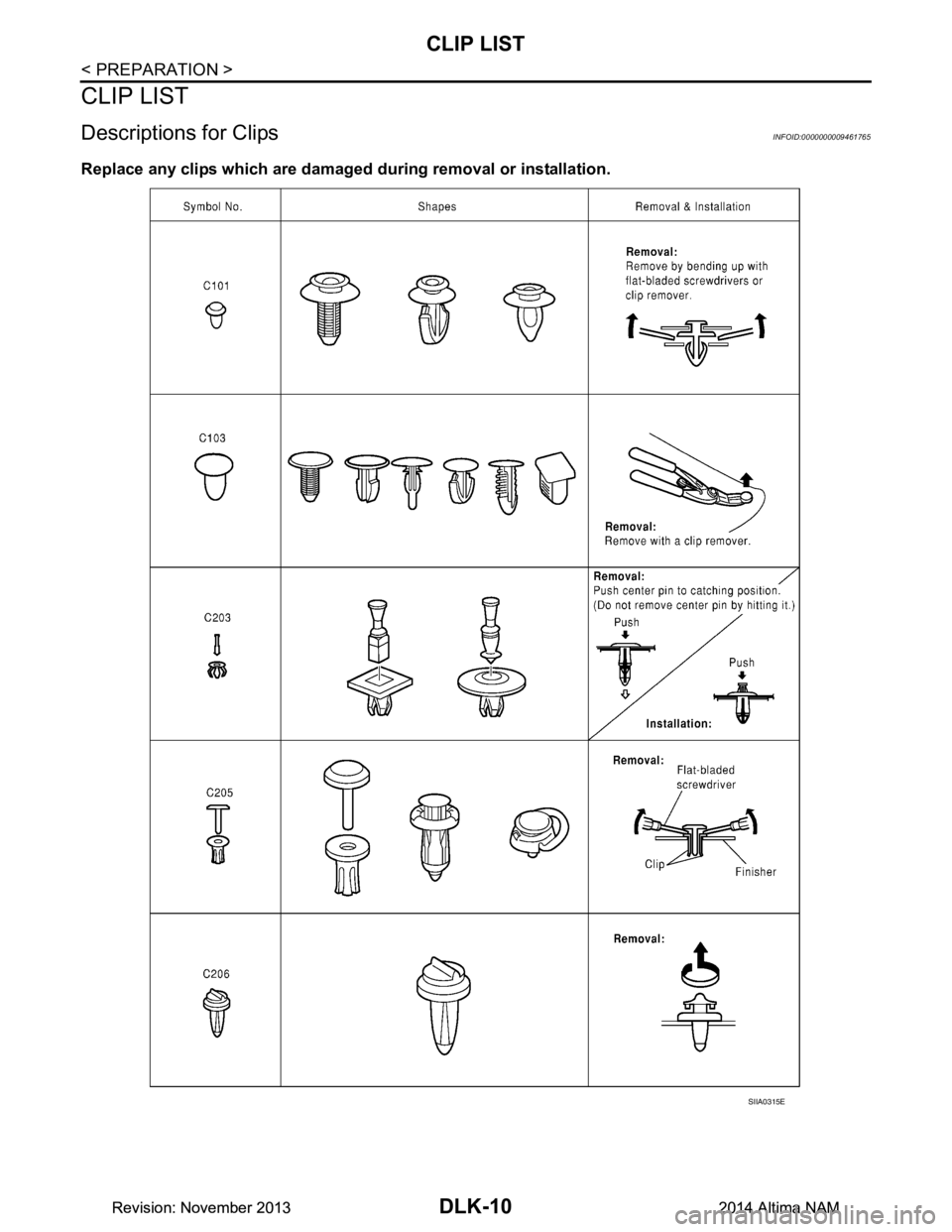
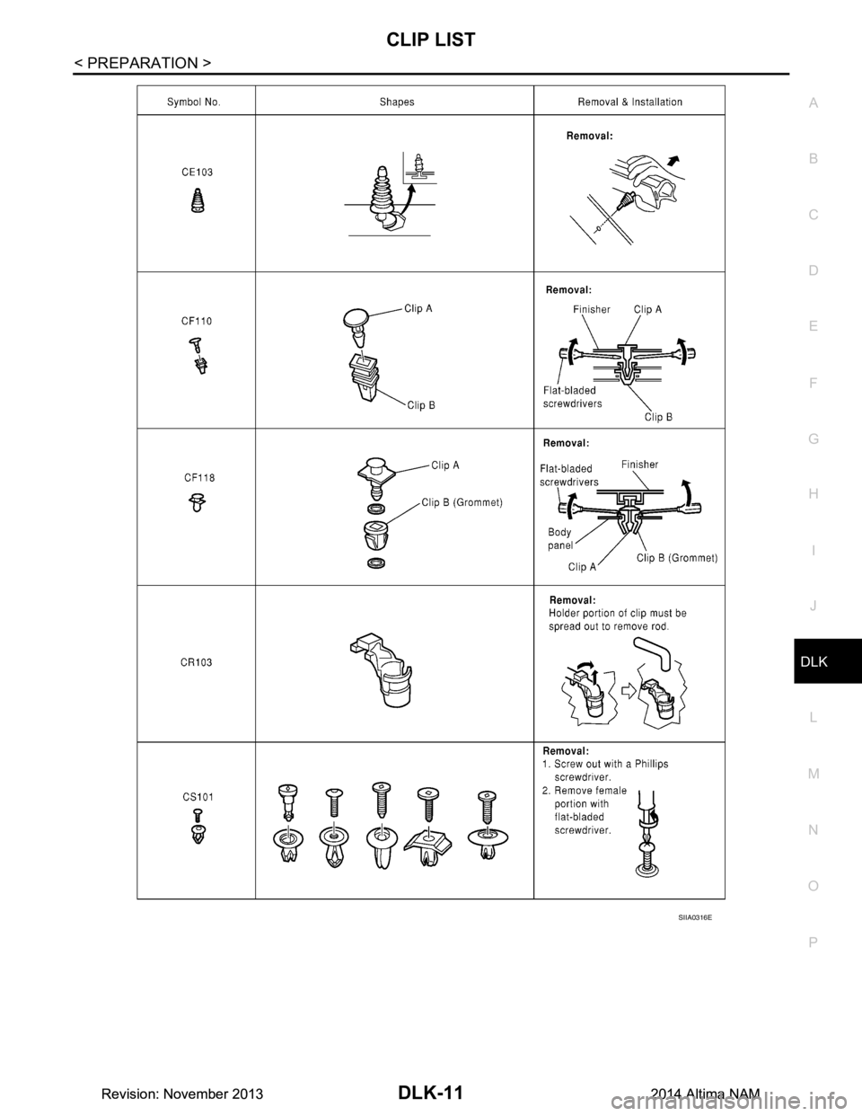
Descriptions for ClipsINFOID:0000000009461765
Replace any clips which are damaged during removal or installation.
SIIA0315E
Revision: November 20132014 Altima NAMRevision: November 20132014 Altima NAM
Page 779 of 4801
CLIP LISTDLK-11
< PREPARATION >
C
D E
F
G H
I
J
L
M A
B
DLK
N
O P
SIIA0316E
Revision: November 20132014 Altima NAMRevision: November 20132014 Altima NAM
Page 780 of 4801

DLK-12
< PREPARATION >
CLIP LIST
SIIA0317E
Revision: November 20132014 Altima NAMRevision: November 20132014 Altima NAM