NISSAN TERRANO 2002 Service Repair Manual
Manufacturer: NISSAN, Model Year: 2002, Model line: TERRANO, Model: NISSAN TERRANO 2002Pages: 1767, PDF Size: 41.51 MB
Page 1491 of 1767
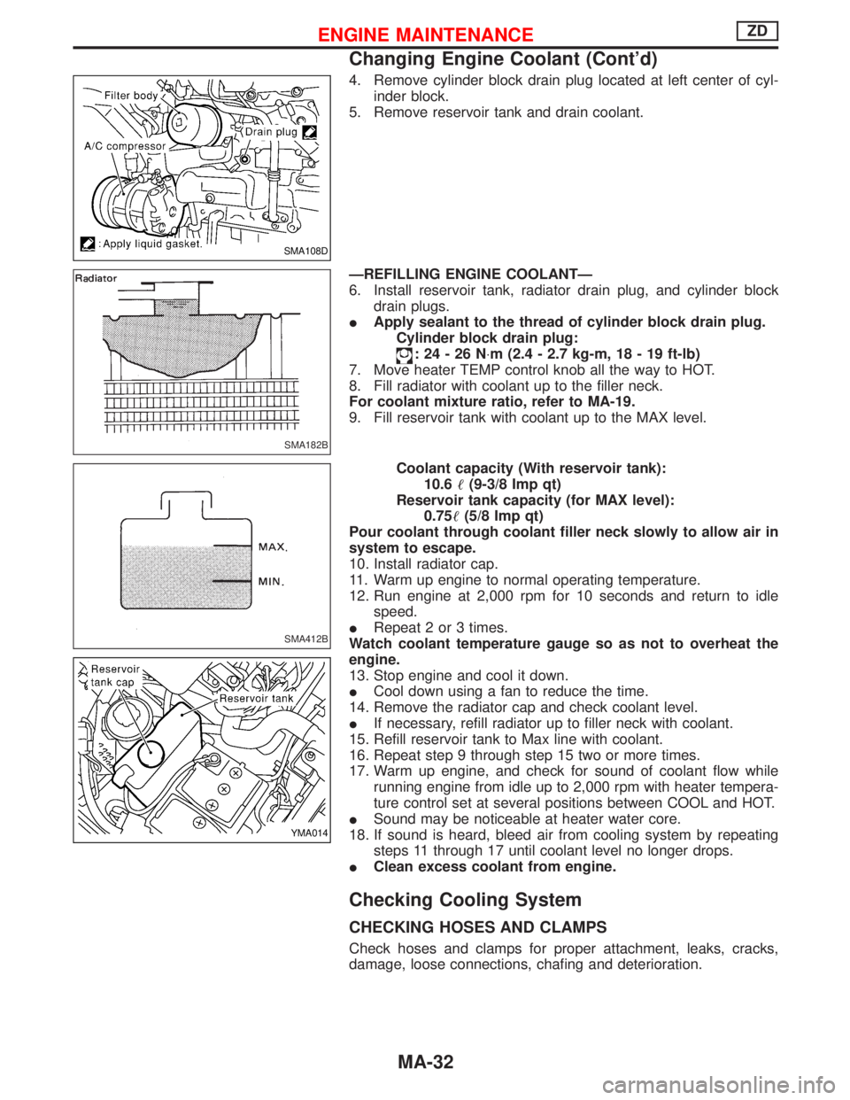
4. Remove cylinder block drain plug located at left center of cyl-
inder block.
5. Remove reservoir tank and drain coolant.
ÐREFILLING ENGINE COOLANTÐ
6. Install reservoir tank, radiator drain plug, and cylinder block
drain plugs.
IApply sealant to the thread of cylinder block drain plug.
Cylinder block drain plug:
:24-26N×m (2.4 - 2.7 kg-m, 18 - 19 ft-lb)
7. Move heater TEMP control knob all the way to HOT.
8. Fill radiator with coolant up to the filler neck.
For coolant mixture ratio, refer to MA-19.
9. Fill reservoir tank with coolant up to the MAX level.
Coolant capacity (With reservoir tank):
10.6(9-3/8 Imp qt)
Reservoir tank capacity (for MAX level):
0.75(5/8 Imp qt)
Pour coolant through coolant filler neck slowly to allow air in
system to escape.
10. Install radiator cap.
11. Warm up engine to normal operating temperature.
12. Run engine at 2,000 rpm for 10 seconds and return to idle
speed.
IRepeat 2 or 3 times.
Watch coolant temperature gauge so as not to overheat the
engine.
13. Stop engine and cool it down.
ICool down using a fan to reduce the time.
14. Remove the radiator cap and check coolant level.
IIf necessary, refill radiator up to filler neck with coolant.
15. Refill reservoir tank to Max line with coolant.
16. Repeat step 9 through step 15 two or more times.
17. Warm up engine, and check for sound of coolant flow while
running engine from idle up to 2,000 rpm with heater tempera-
ture control set at several positions between COOL and HOT.
ISound may be noticeable at heater water core.
18. If sound is heard, bleed air from cooling system by repeating
steps 11 through 17 until coolant level no longer drops.
IClean excess coolant from engine.
Checking Cooling System
CHECKING HOSES AND CLAMPS
Check hoses and clamps for proper attachment, leaks, cracks,
damage, loose connections, chafing and deterioration.
SMA108D
SMA182B
SMA412B
YMA014
ENGINE MAINTENANCEZD
Changing Engine Coolant (Cont'd)
MA-32
Page 1492 of 1767
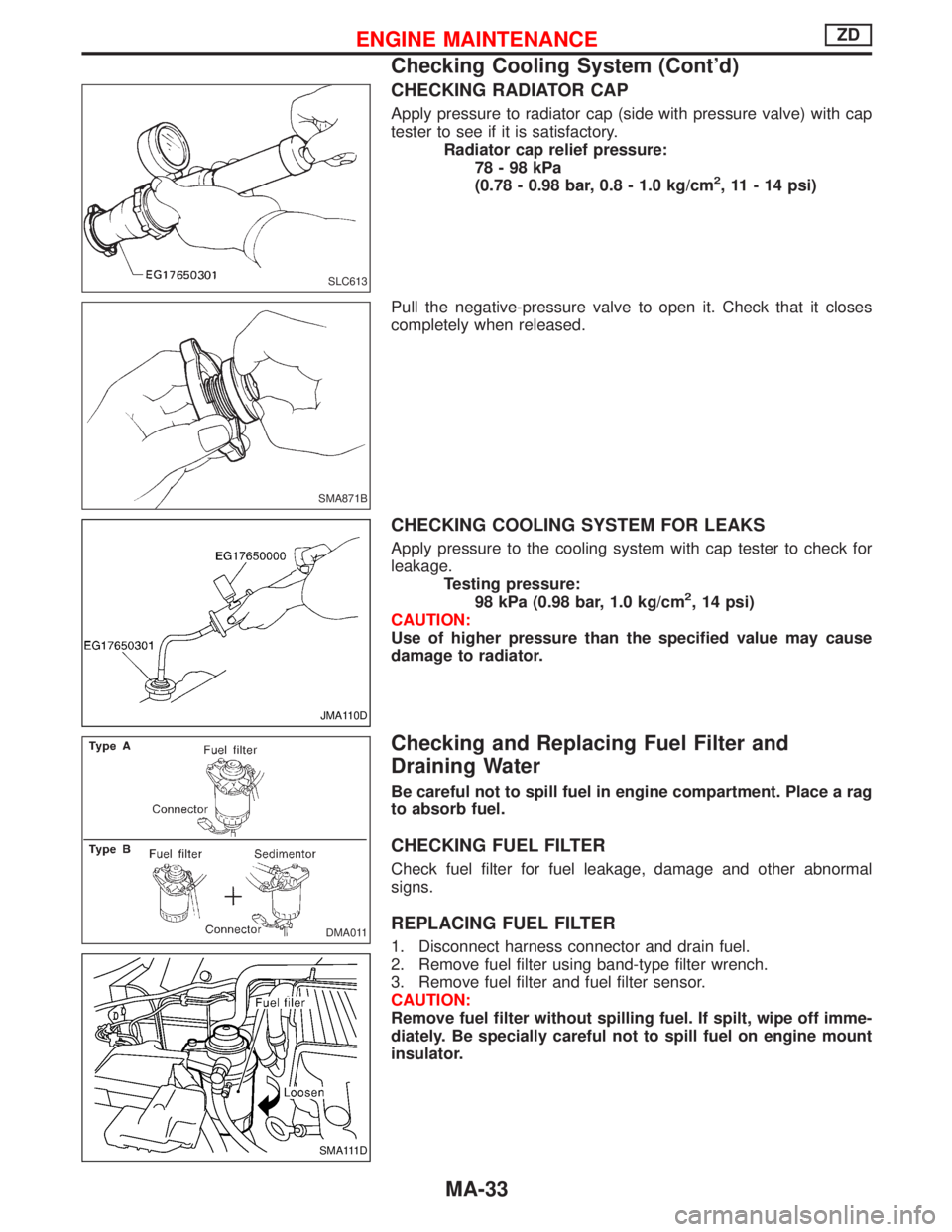
CHECKING RADIATOR CAP
Apply pressure to radiator cap (side with pressure valve) with cap
tester to see if it is satisfactory.
Radiator cap relief pressure:
78-98kPa
(0.78 - 0.98 bar, 0.8 - 1.0 kg/cm
2, 11 - 14 psi)
Pull the negative-pressure valve to open it. Check that it closes
completely when released.
CHECKING COOLING SYSTEM FOR LEAKS
Apply pressure to the cooling system with cap tester to check for
leakage.
Testing pressure:
98 kPa (0.98 bar, 1.0 kg/cm
2, 14 psi)
CAUTION:
Use of higher pressure than the specified value may cause
damage to radiator.
Checking and Replacing Fuel Filter and
Draining Water
Be careful not to spill fuel in engine compartment. Place a rag
to absorb fuel.
CHECKING FUEL FILTER
Check fuel filter for fuel leakage, damage and other abnormal
signs.
REPLACING FUEL FILTER
1. Disconnect harness connector and drain fuel.
2. Remove fuel filter using band-type filter wrench.
3. Remove fuel filter and fuel filter sensor.
CAUTION:
Remove fuel filter without spilling fuel. If spilt, wipe off imme-
diately. Be specially careful not to spill fuel on engine mount
insulator.
SLC613
SMA871B
JMA110D
DMA011
SMA111D
ENGINE MAINTENANCEZD
Checking Cooling System (Cont'd)
MA-33
Page 1493 of 1767
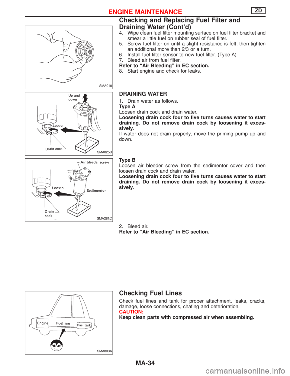
4. Wipe clean fuel filter mounting surface on fuel filter bracket and
smear a little fuel on rubber seal of fuel filter.
5. Screw fuel filter on until a slight resistance is felt, then tighten
an additional more than 2/3 or a turn.
6. Install fuel filter sensor to new fuel filter. (Type A)
7. Bleed air from fuel filter.
Refer to ªAir Bleedingº in EC section.
8. Start engine and check for leaks.
DRAINING WATER
1. Drain water as follows.
Type A
Loosen drain cock and drain water.
Loosening drain cock four to five turns causes water to start
draining. Do not remove drain cock by loosening it exces-
sively.
If water does not drain properly, move the priming pump up and
down.
Type B
Loosen air bleeder screw from the sedimentor cover and then
loosen drain cock and drain water.
Loosening drain cock four to five turns causes water to start
draining. Do not remove drain cock by loosening it exces-
sively.
2. Bleed air.
Refer to ªAir Bleedingº in EC section.
Checking Fuel Lines
Check fuel lines and tank for proper attachment, leaks, cracks,
damage, loose connections, chafing and deterioration.
CAUTION:
Keep clean parts with compressed air when assembling.
SMA010
SMA825B
SMA281C
SMA803A
ENGINE MAINTENANCEZD
Checking and Replacing Fuel Filter and
Draining Water (Cont'd)
MA-34
Page 1494 of 1767
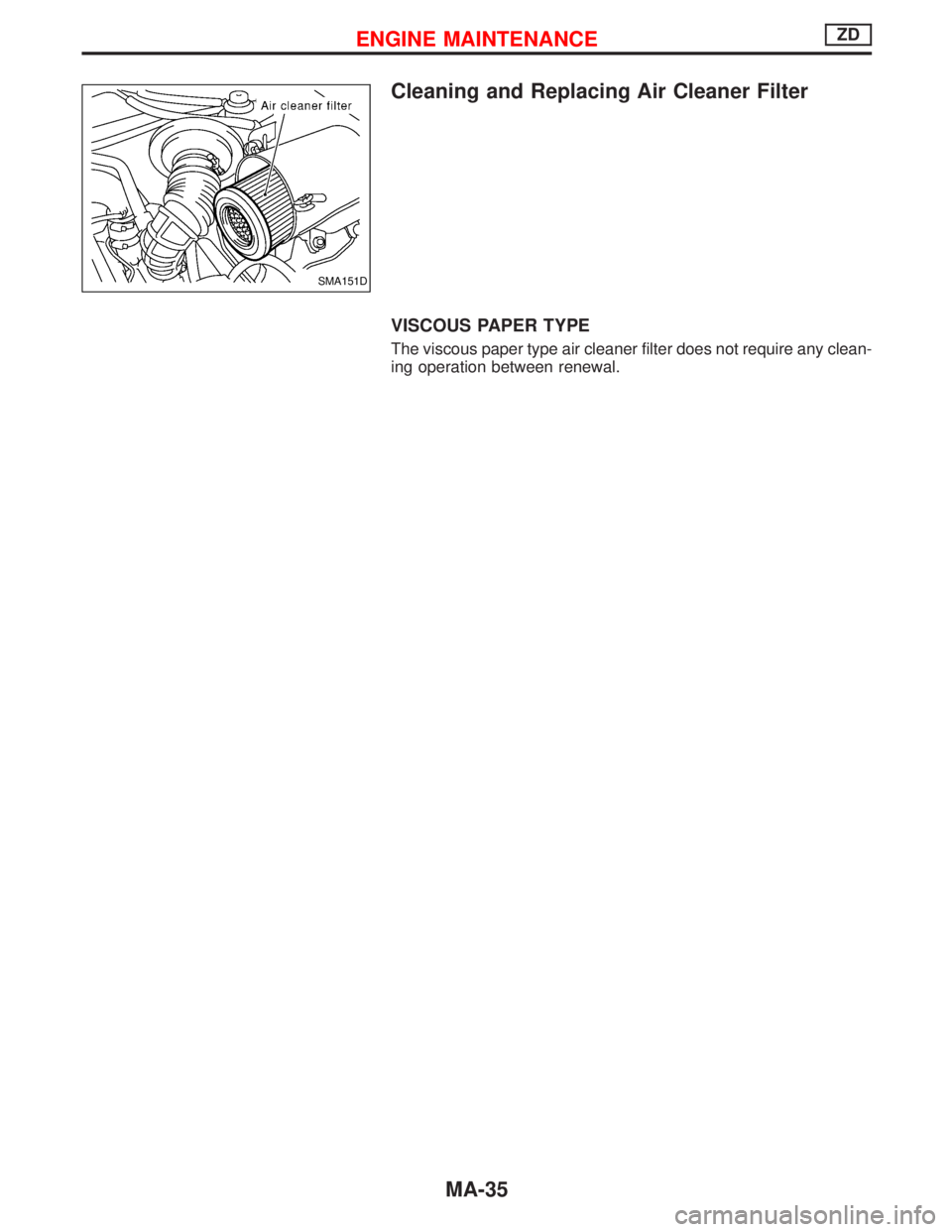
Cleaning and Replacing Air Cleaner Filter
VISCOUS PAPER TYPE
The viscous paper type air cleaner filter does not require any clean-
ing operation between renewal.
SMA151D
ENGINE MAINTENANCEZD
MA-35
Page 1495 of 1767
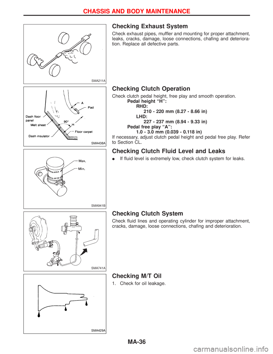
Checking Exhaust System
Check exhaust pipes, muffler and mounting for proper attachment,
leaks, cracks, damage, loose connections, chafing and deteriora-
tion. Replace all defective parts.
Checking Clutch Operation
Check clutch pedal height, free play and smooth operation.
Pedal height ªHº:
RHD:
210 - 220 mm (8.27 - 8.66 in)
LHD:
227 - 237 mm (8.94 - 9.33 in)
Pedal free play ªAº:
1.0 - 3.0 mm (0.039 - 0.118 in)
If necessary, adjust clutch pedal height and pedal free play. Refer
to Section CL.
Checking Clutch Fluid Level and Leaks
IIf fluid level is extremely low, check clutch system for leaks.
Checking Clutch System
Check fluid lines and operating cylinder for improper attachment,
cracks, damage, loose connections, chafing and deterioration.
Checking M/T Oil
1. Check for oil leakage.
SMA211A
SMA438A
SMA941B
SMA741A
SMA429A
CHASSIS AND BODY MAINTENANCE
MA-36
Page 1496 of 1767
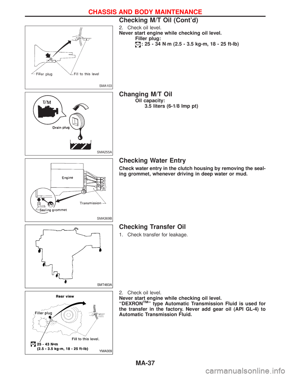
2. Check oil level.
Never start engine while checking oil level.
Filler plug:
:25-34N×m (2.5 - 3.5 kg-m, 18 - 25 ft-lb)
Changing M/T Oil
Oil capacity:
3.5 liters (6-1/8 Imp pt)
Checking Water Entry
Check water entry in the clutch housing by removing the seal-
ing grommet, whenever driving in deep water or mud.
Checking Transfer Oil
1. Check transfer for leakage.
2. Check oil level.
Never start engine while checking oil level.
ªDEXRON
TMº type Automatic Transmission Fluid is used for
the transfer in the factory. Never add gear oil (API GL-4) to
Automatic Transmission Fluid.
SMA103
SMA255A
SMA369B
SMT483A
YMA009
CHASSIS AND BODY MAINTENANCE
Checking M/T Oil (Cont'd)
MA-37
Page 1497 of 1767
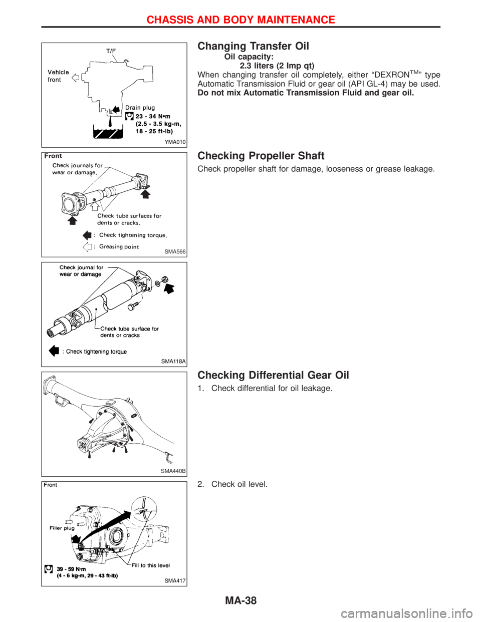
Changing Transfer Oil
Oil capacity:
2.3 liters (2 Imp qt)
When changing transfer oil completely, either ªDEXRON
TMº type
Automatic Transmission Fluid or gear oil (API GL-4) may be used.
Do not mix Automatic Transmission Fluid and gear oil.
Checking Propeller Shaft
Check propeller shaft for damage, looseness or grease leakage.
Checking Differential Gear Oil
1. Check differential for oil leakage.
2. Check oil level.
YMA010
SMA566
SMA118A
SMA440B
SMA417
CHASSIS AND BODY MAINTENANCE
MA-38
Page 1498 of 1767
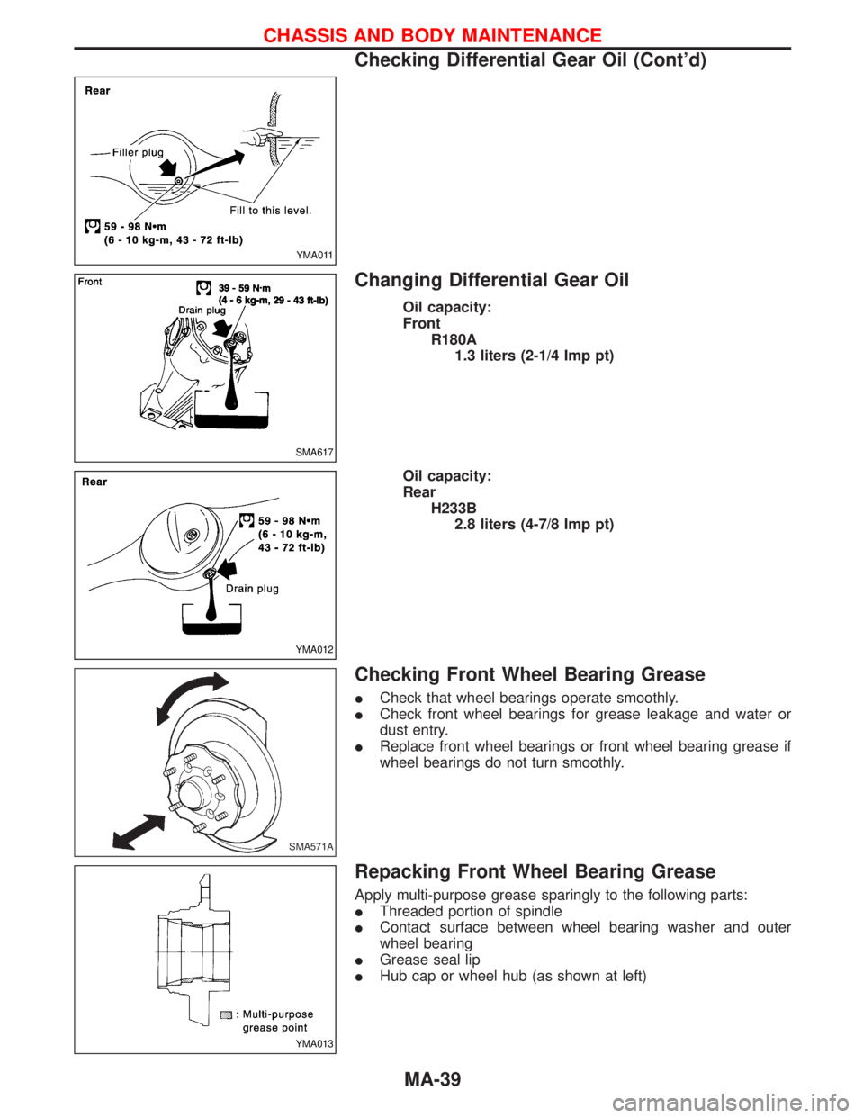
Changing Differential Gear Oil
Oil capacity:
Front
R180A
1.3 liters (2-1/4 Imp pt)
Oil capacity:
Rear
H233B
2.8 liters (4-7/8 Imp pt)
Checking Front Wheel Bearing Grease
ICheck that wheel bearings operate smoothly.
ICheck front wheel bearings for grease leakage and water or
dust entry.
IReplace front wheel bearings or front wheel bearing grease if
wheel bearings do not turn smoothly.
Repacking Front Wheel Bearing Grease
Apply multi-purpose grease sparingly to the following parts:
IThreaded portion of spindle
IContact surface between wheel bearing washer and outer
wheel bearing
IGrease seal lip
IHub cap or wheel hub (as shown at left)
YMA011
SMA617
YMA012
SMA571A
YMA013
CHASSIS AND BODY MAINTENANCE
Checking Differential Gear Oil (Cont'd)
MA-39
Page 1499 of 1767
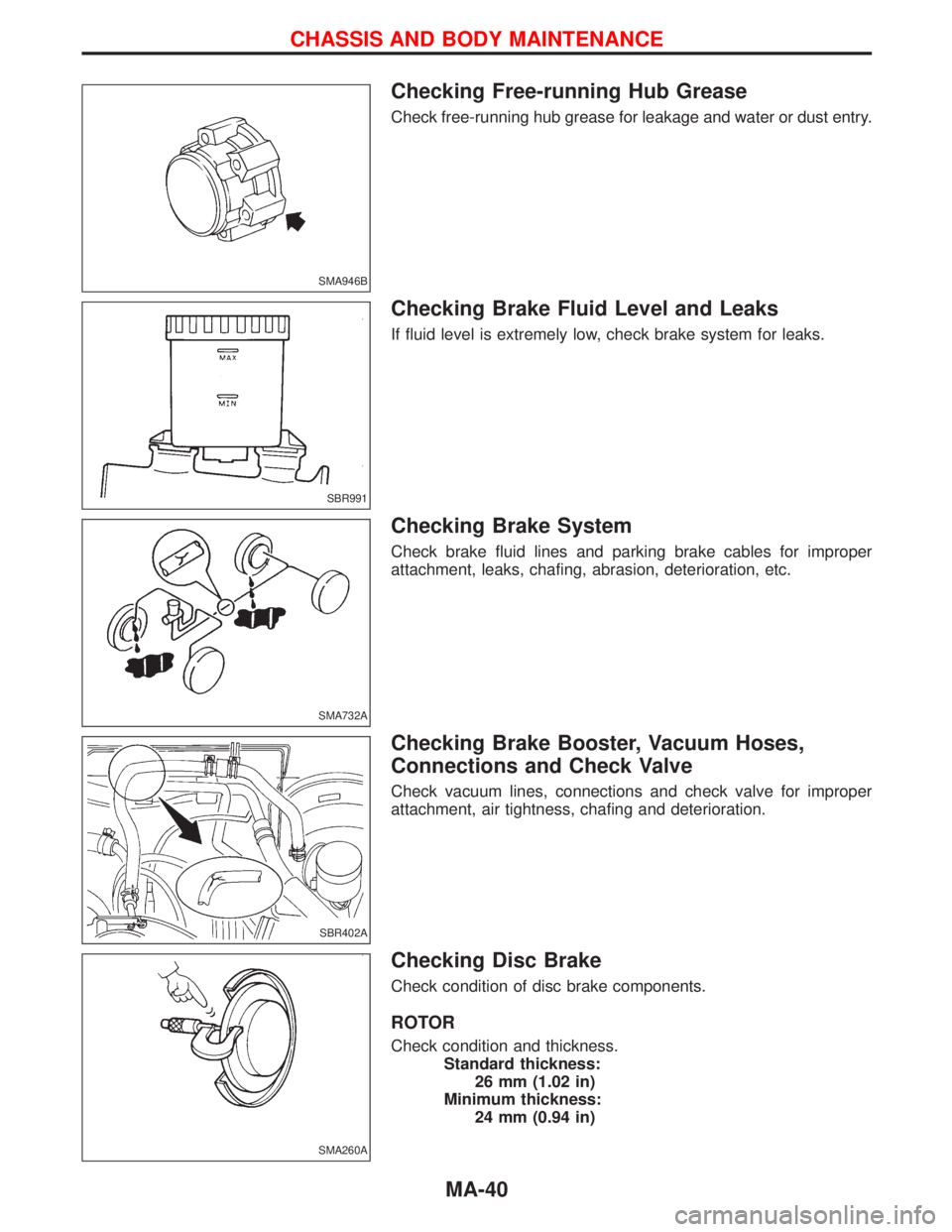
Checking Free-running Hub Grease
Check free-running hub grease for leakage and water or dust entry.
Checking Brake Fluid Level and Leaks
If fluid level is extremely low, check brake system for leaks.
Checking Brake System
Check brake fluid lines and parking brake cables for improper
attachment, leaks, chafing, abrasion, deterioration, etc.
Checking Brake Booster, Vacuum Hoses,
Connections and Check Valve
Check vacuum lines, connections and check valve for improper
attachment, air tightness, chafing and deterioration.
Checking Disc Brake
Check condition of disc brake components.
ROTOR
Check condition and thickness.
Standard thickness:
26 mm (1.02 in)
Minimum thickness:
24 mm (0.94 in)
SMA946B
SBR991
SMA732A
SBR402A
SMA260A
CHASSIS AND BODY MAINTENANCE
MA-40
Page 1500 of 1767
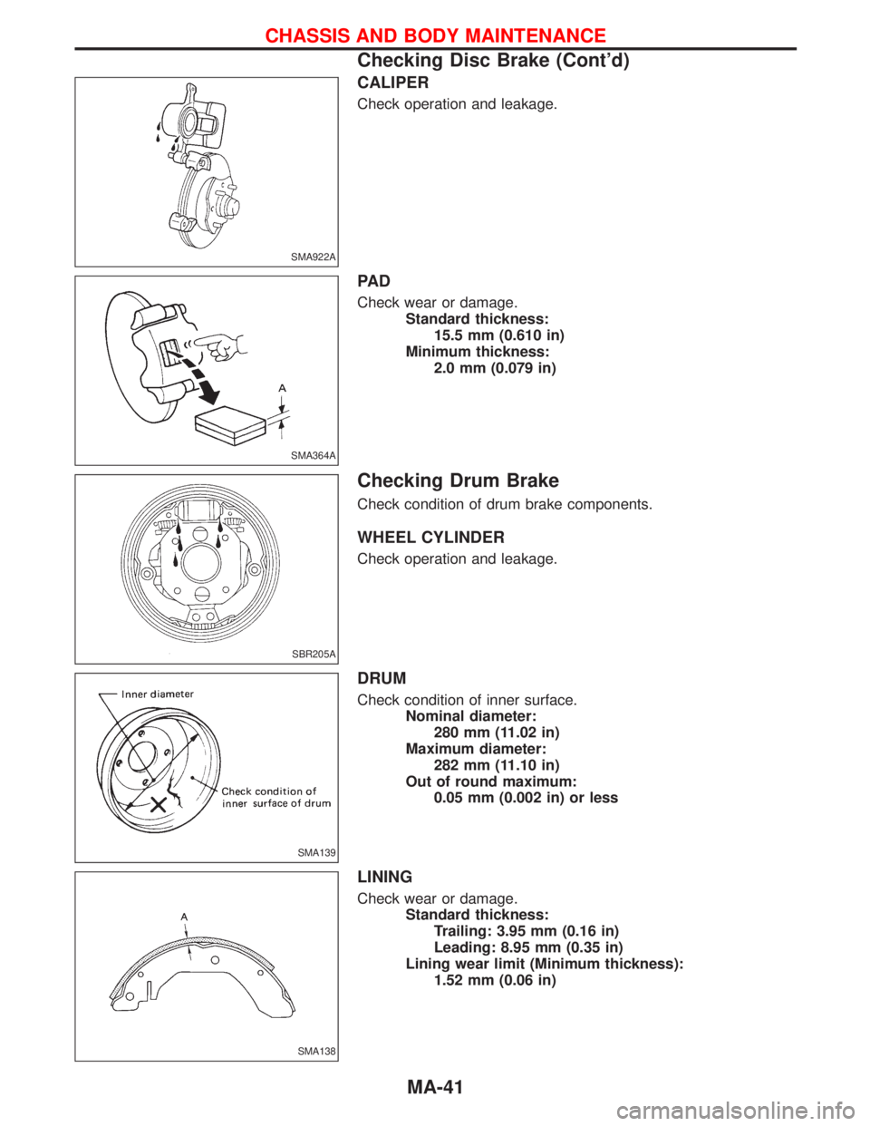
CALIPER
Check operation and leakage.
PA D
Check wear or damage.
Standard thickness:
15.5 mm (0.610 in)
Minimum thickness:
2.0 mm (0.079 in)
Checking Drum Brake
Check condition of drum brake components.
WHEEL CYLINDER
Check operation and leakage.
DRUM
Check condition of inner surface.
Nominal diameter:
280 mm (11.02 in)
Maximum diameter:
282 mm (11.10 in)
Out of round maximum:
0.05 mm (0.002 in) or less
LINING
Check wear or damage.
Standard thickness:
Trailing: 3.95 mm (0.16 in)
Leading: 8.95 mm (0.35 in)
Lining wear limit (Minimum thickness):
1.52 mm (0.06 in)
SMA922A
SMA364A
SBR205A
SMA139
SMA138
CHASSIS AND BODY MAINTENANCE
Checking Disc Brake (Cont'd)
MA-41