NISSAN TERRANO 2002 Service Repair Manual
Manufacturer: NISSAN, Model Year: 2002, Model line: TERRANO, Model: NISSAN TERRANO 2002Pages: 1767, PDF Size: 41.51 MB
Page 1501 of 1767
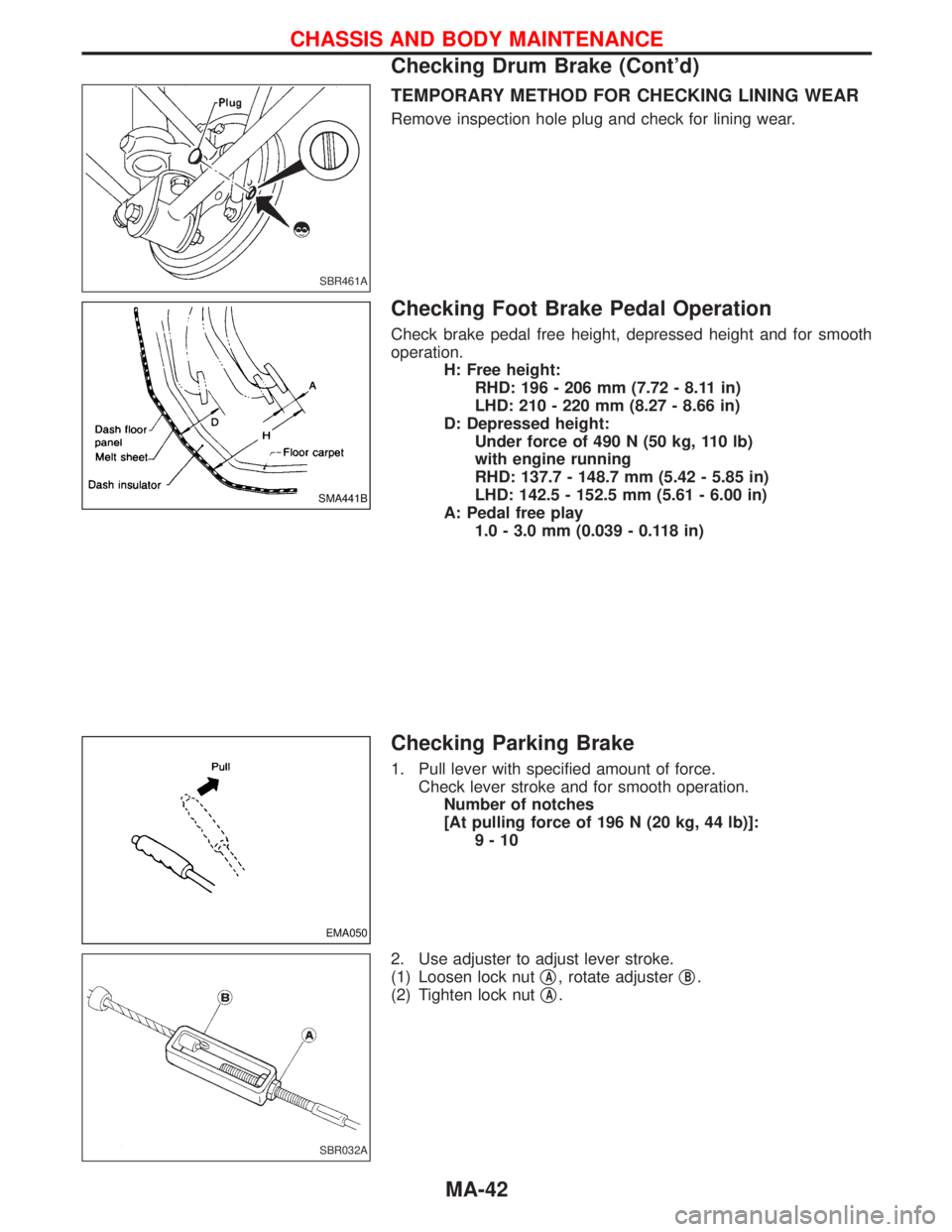
TEMPORARY METHOD FOR CHECKING LINING WEAR
Remove inspection hole plug and check for lining wear.
Checking Foot Brake Pedal Operation
Check brake pedal free height, depressed height and for smooth
operation.
H: Free height:
RHD: 196 - 206 mm (7.72 - 8.11 in)
LHD: 210 - 220 mm (8.27 - 8.66 in)
D: Depressed height:
Under force of 490 N (50 kg, 110 lb)
with engine running
RHD: 137.7 - 148.7 mm (5.42 - 5.85 in)
LHD: 142.5 - 152.5 mm (5.61 - 6.00 in)
A: Pedal free play
1.0 - 3.0 mm (0.039 - 0.118 in)
Checking Parking Brake
1. Pull lever with specified amount of force.
Check lever stroke and for smooth operation.
Number of notches
[At pulling force of 196 N (20 kg, 44 lb)]:
9-10
2. Use adjuster to adjust lever stroke.
(1) Loosen lock nutq
A, rotate adjusterqB.
(2) Tighten lock nutq
A.
SBR461A
SMA441B
EMA050
SBR032A
CHASSIS AND BODY MAINTENANCE
Checking Drum Brake (Cont'd)
MA-42
Page 1502 of 1767
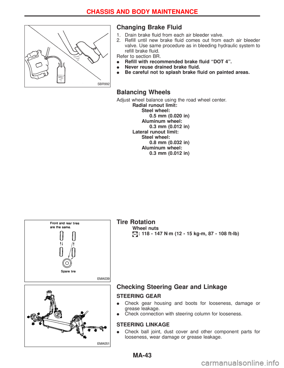
Changing Brake Fluid
1. Drain brake fluid from each air bleeder valve.
2. Refill until new brake fluid comes out from each air bleeder
valve. Use same procedure as in bleeding hydraulic system to
refill brake fluid.
Refer to section BR.
IRefill with recommended brake fluid ªDOT 4º.
INever reuse drained brake fluid.
IBe careful not to splash brake fluid on painted areas.
Balancing Wheels
Adjust wheel balance using the road wheel center.
Radial runout limit:
Steel wheel:
0.5 mm (0.020 in)
Aluminum wheel:
0.3 mm (0.012 in)
Lateral runout limit:
Steel wheel:
0.8 mm (0.032 in)
Aluminum wheel:
0.3 mm (0.012 in)
Tire Rotation
Wheel nuts
: 118 - 147 N×m (12 - 15 kg-m, 87 - 108 ft-lb)
Checking Steering Gear and Linkage
STEERING GEAR
ICheck gear housing and boots for looseness, damage or
grease leakage.
ICheck connection with steering column for looseness.
STEERING LINKAGE
ICheck ball joint, dust cover and other component parts for
looseness, wear damage or grease leakage.
SBR992
EMA039
EMA051
CHASSIS AND BODY MAINTENANCE
MA-43
Page 1503 of 1767
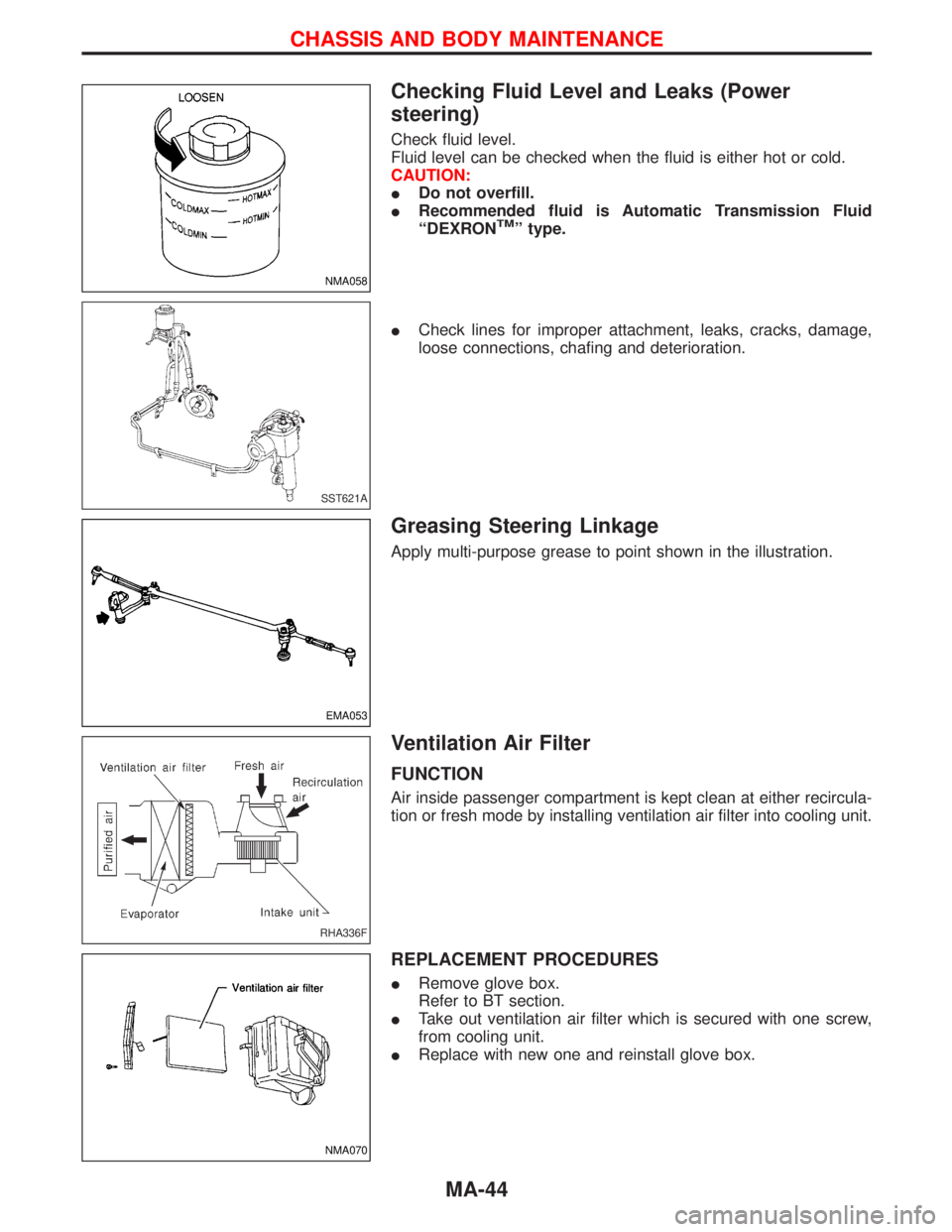
Checking Fluid Level and Leaks (Power
steering)
Check fluid level.
Fluid level can be checked when the fluid is either hot or cold.
CAUTION:
IDo not overfill.
IRecommended fluid is Automatic Transmission Fluid
ªDEXRON
TMº type.
ICheck lines for improper attachment, leaks, cracks, damage,
loose connections, chafing and deterioration.
Greasing Steering Linkage
Apply multi-purpose grease to point shown in the illustration.
Ventilation Air Filter
FUNCTION
Air inside passenger compartment is kept clean at either recircula-
tion or fresh mode by installing ventilation air filter into cooling unit.
REPLACEMENT PROCEDURES
IRemove glove box.
Refer to BT section.
ITake out ventilation air filter which is secured with one screw,
from cooling unit.
IReplace with new one and reinstall glove box.
NMA058
SST621A
EMA053
RHA336F
NMA070
CHASSIS AND BODY MAINTENANCE
MA-44
Page 1504 of 1767
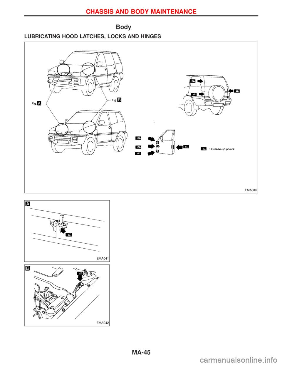
Body
LUBRICATING HOOD LATCHES, LOCKS AND HINGES
EMA040
EMA041
EMA042
CHASSIS AND BODY MAINTENANCE
MA-45
Page 1505 of 1767
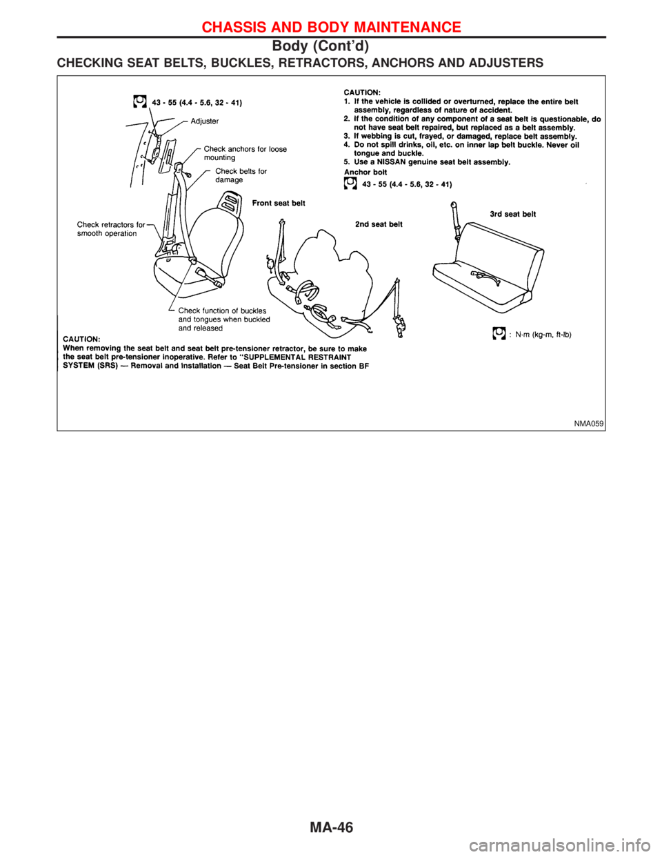
CHECKING SEAT BELTS, BUCKLES, RETRACTORS, ANCHORS AND ADJUSTERS
NMA059
CHASSIS AND BODY MAINTENANCE
Body (Cont'd)
MA-46
Page 1506 of 1767
Checking Body Corrosion
Visually check the body sheet metal panel for corrosion, paint damage (scratches, chipping, rubbing, etc.) or
damage to the anti-corrosion materials. In particular, check the following locations.
Hemmed portion
Hood front end, door lower end, trunk lid rear end, etc.
Panel joint
Side sill of rear fender and center pillar, rear wheel housing of rear fender, around strut lower in engine
compartment, etc.
Panel edge
Trunk lid opening, sun roof opening, fender wheel-arch flange, fuel filler lid flange, around holes in panel, etc.
Parts contact
Waist moulding, windshield moulding, bumper, etc.
Protectors
Damage or condition of mudguard, fender protector, chipping protector, etc.
Anti-corrosion materials
Damage or separation of anti-corrosion materials under the body.
Drain holes
Condition of drain holes at door and side sill.
When repairing corroded areas, refer to the Corrosion Repair Manual.
CHASSIS AND BODY MAINTENANCE
MA-47
Page 1507 of 1767
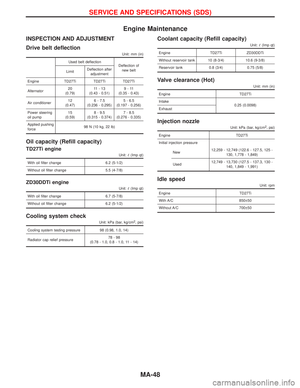
Engine Maintenance
INSPECTION AND ADJUSTMENT
Drive belt deflection
Unit: mm (in)
Used belt deflection
Deflection of
new belt
LimitDeflection after
adjustment
Engine TD27Ti TD27Ti TD27Ti
Alternator20
(0.79)11-13
(0.43 - 0.51)9-11
(0.35 - 0.43)
Air conditioner12
(0.47)6 - 7.5
(0.236 - 0.295)5 - 6.5
(0.197 - 0.256)
Power steering
oil pump15
(0.59)8 - 9.5
(0.315 - 0.374)7 - 8.5
(0.276 - 0.335)
Applied pushing
force98 N (10 kg, 22 lb)
Oil capacity (Refill capacity)
TD27Ti engine
Unit:(Imp qt)
With oil filter change 6.2 (5-1/2)
Without oil filter change 5.5 (4-7/8)
ZD30DDTi engine
Unit:(Imp qt)
With oil filter change 6.7 (5-7/8)
Without oil filter change 6.2 (5-1/2)
Cooling system check
Unit: kPa (bar, kg/cm2, psi)
Cooling system testing pressure 98 (0.98, 1.0, 14)
Radiator cap relief pressure78-98
(0.78 - 1.0, 0.8 - 1.0, 11 - 14)
Coolant capacity (Refill capacity)
Unit:(Imp qt)
Engine TD27Ti ZD30DDTi
Without reservoir tank 10 (8-3/4) 10.6 (9-3/8)
Reservoir tank 0.8 (3/4) 0.75 (5/8)
Valve clearance (Hot)
Unit: mm (in)
Engine TD27Ti
Intake
0.25 (0.0098)
Exhaust
Injection nozzle
Unit: kPa (bar, kg/cm2, psi)
Engine TD27Ti
Initial injection pressure
New12,259 - 12,749 (122.6 - 127.5, 125 -
130, 1,778 - 1,849)
Used12,749 - 13,730 (127.5 - 137.3, 130 -
140, 1,849 - 1,991)
Idle speed
Unit: rpm
Engine TD27Ti
With A/C 850 50
Without A/C 700 50
SERVICE AND SPECIFICATIONS (SDS)
MA-48
Page 1508 of 1767
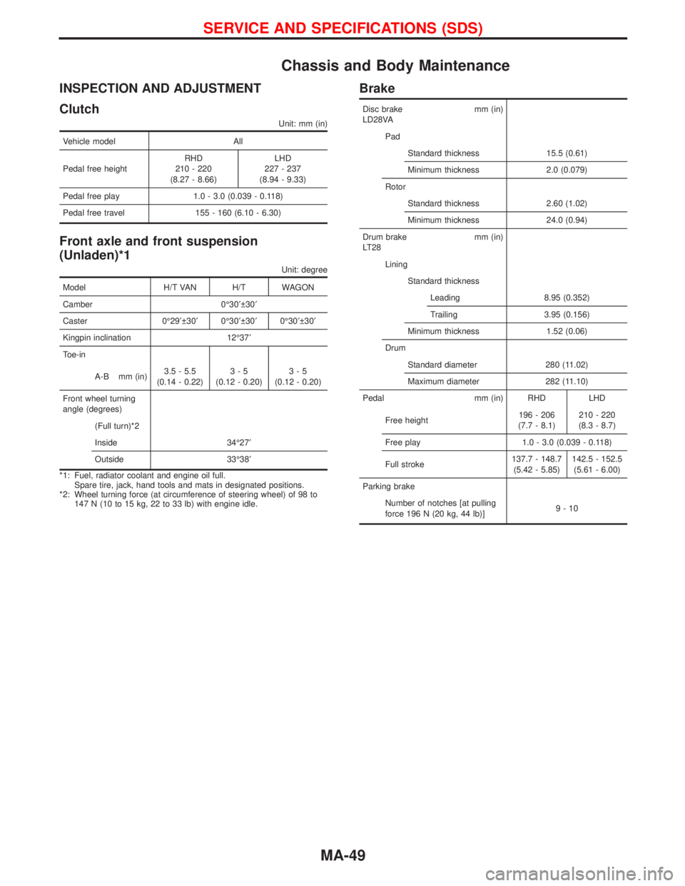
Chassis and Body Maintenance
INSPECTION AND ADJUSTMENT
Clutch
Unit: mm (in)
Vehicle model All
Pedal free heightRHD
210 - 220
(8.27 - 8.66)LHD
227 - 237
(8.94 - 9.33)
Pedal free play 1.0 - 3.0 (0.039 - 0.118)
Pedal free travel 155 - 160 (6.10 - 6.30)
Front axle and front suspension
(Unladen)*1
Unit: degree
Model H/T VAN H/T WAGON
Camber 0É30¢ 30¢
Caster 0É29¢ 30¢0É30¢ 30¢0É30¢ 30¢
Kingpin inclination 12É37¢
Toe-in
A-B mm (in)3.5 - 5.5
(0.14 - 0.22)3-5
(0.12 - 0.20)3-5
(0.12 - 0.20)
Front wheel turning
angle (degrees)
(Full turn)*2
Inside 34É27¢
Outside 33É38¢
*1: Fuel, radiator coolant and engine oil full.
Spare tire, jack, hand tools and mats in designated positions.
*2: Wheel turning force (at circumference of steering wheel) of 98 to
147 N (10 to 15 kg, 22 to 33 lb) with engine idle.
Brake
Disc brake mm (in)
LD28VA
Pad
Standard thickness 15.5 (0.61)
Minimum thickness 2.0 (0.079)
Rotor
Standard thickness 2.60 (1.02)
Minimum thickness 24.0 (0.94)
Drum brake mm (in)
LT28
Lining
Standard thickness
Leading 8.95 (0.352)
Trailing 3.95 (0.156)
Minimum thickness 1.52 (0.06)
Drum
Standard diameter 280 (11.02)
Maximum diameter 282 (11.10)
Pedal mm (in) RHD LHD
Free height196 - 206
(7.7 - 8.1)210 - 220
(8.3 - 8.7)
Free play 1.0 - 3.0 (0.039 - 0.118)
Full stroke137.7 - 148.7
(5.42 - 5.85)142.5 - 152.5
(5.61 - 6.00)
Parking brake
Number of notches [at pulling
force 196 N (20 kg, 44 lb)]9-10
SERVICE AND SPECIFICATIONS (SDS)
MA-49
Page 1509 of 1767
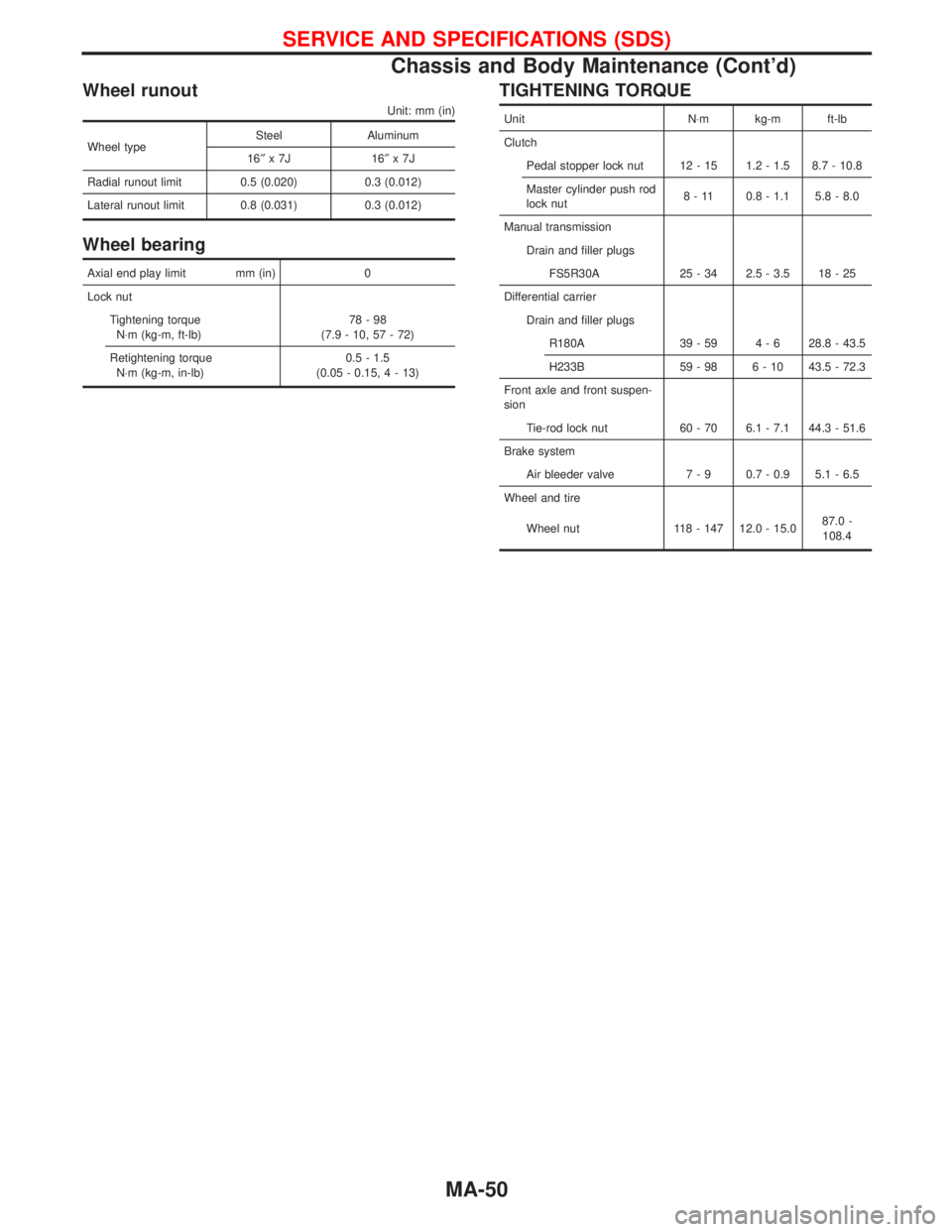
Wheel runout
Unit: mm (in)
Wheel typeSteel Aluminum
16²x7J 16²x7J
Radial runout limit 0.5 (0.020) 0.3 (0.012)
Lateral runout limit 0.8 (0.031) 0.3 (0.012)
Wheel bearing
Axial end play limit mm (in) 0
Lock nut
Tightening torque
N×m (kg-m, ft-lb)78-98
(7.9 - 10, 57 - 72)
Retightening torque
N×m (kg-m, in-lb)0.5 - 1.5
(0.05 - 0.15,4-13)
TIGHTENING TORQUE
Unit N×m kg-m ft-lb
Clutch
Pedal stopper lock nut 12 - 15 1.2 - 1.5 8.7 - 10.8
Master cylinder push rod
lock nut8 - 11 0.8 - 1.1 5.8 - 8.0
Manual transmission
Drain and filler plugs
FS5R30A 25 - 34 2.5 - 3.5 18 - 25
Differential carrier
Drain and filler plugs
R180A 39 - 59 4 - 6 28.8 - 43.5
H233B 59 - 98 6 - 10 43.5 - 72.3
Front axle and front suspen-
sion
Tie-rod lock nut 60 - 70 6.1 - 7.1 44.3 - 51.6
Brake system
Air bleeder valve 7 - 9 0.7 - 0.9 5.1 - 6.5
Wheel and tire
Wheel nut 118 - 147 12.0 - 15.087.0 -
108.4
SERVICE AND SPECIFICATIONS (SDS)
Chassis and Body Maintenance (Cont'd)
MA-50
Page 1510 of 1767
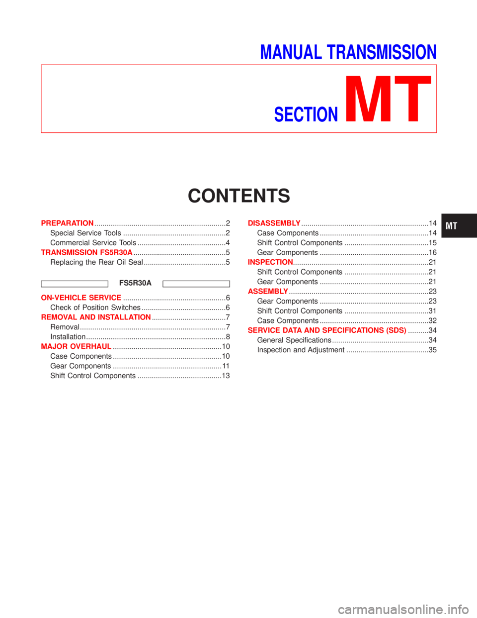
MANUAL TRANSMISSION
SECTION
MT
CONTENTS
PREPARATION................................................................2
Special Service Tools ..................................................2
Commercial Service Tools ...........................................4
TRANSMISSION FS5R30A.............................................5
Replacing the Rear Oil Seal ........................................5
FS5R30A
ON-VEHICLE SERVICE..................................................6
Check of Position Switches .........................................6
REMOVAL AND INSTALLATION....................................7
Removal .......................................................................7
Installation ....................................................................8
MAJOR OVERHAUL.....................................................10
Case Components .....................................................10
Gear Components ..................................................... 11
Shift Control Components .........................................13DISASSEMBLY..............................................................14
Case Components .....................................................14
Shift Control Components .........................................15
Gear Components .....................................................16
INSPECTION..................................................................21
Shift Control Components .........................................21
Gear Components .....................................................21
ASSEMBLY....................................................................23
Gear Components .....................................................23
Shift Control Components .........................................31
Case Components .....................................................32
SERVICE DATA AND SPECIFICATIONS (SDS)..........34
General Specifications ...............................................34
Inspection and Adjustment ........................................35