Brake NISSAN TERRANO 2002 Service Owner's Manual
[x] Cancel search | Manufacturer: NISSAN, Model Year: 2002, Model line: TERRANO, Model: NISSAN TERRANO 2002Pages: 1767, PDF Size: 41.51 MB
Page 103 of 1767
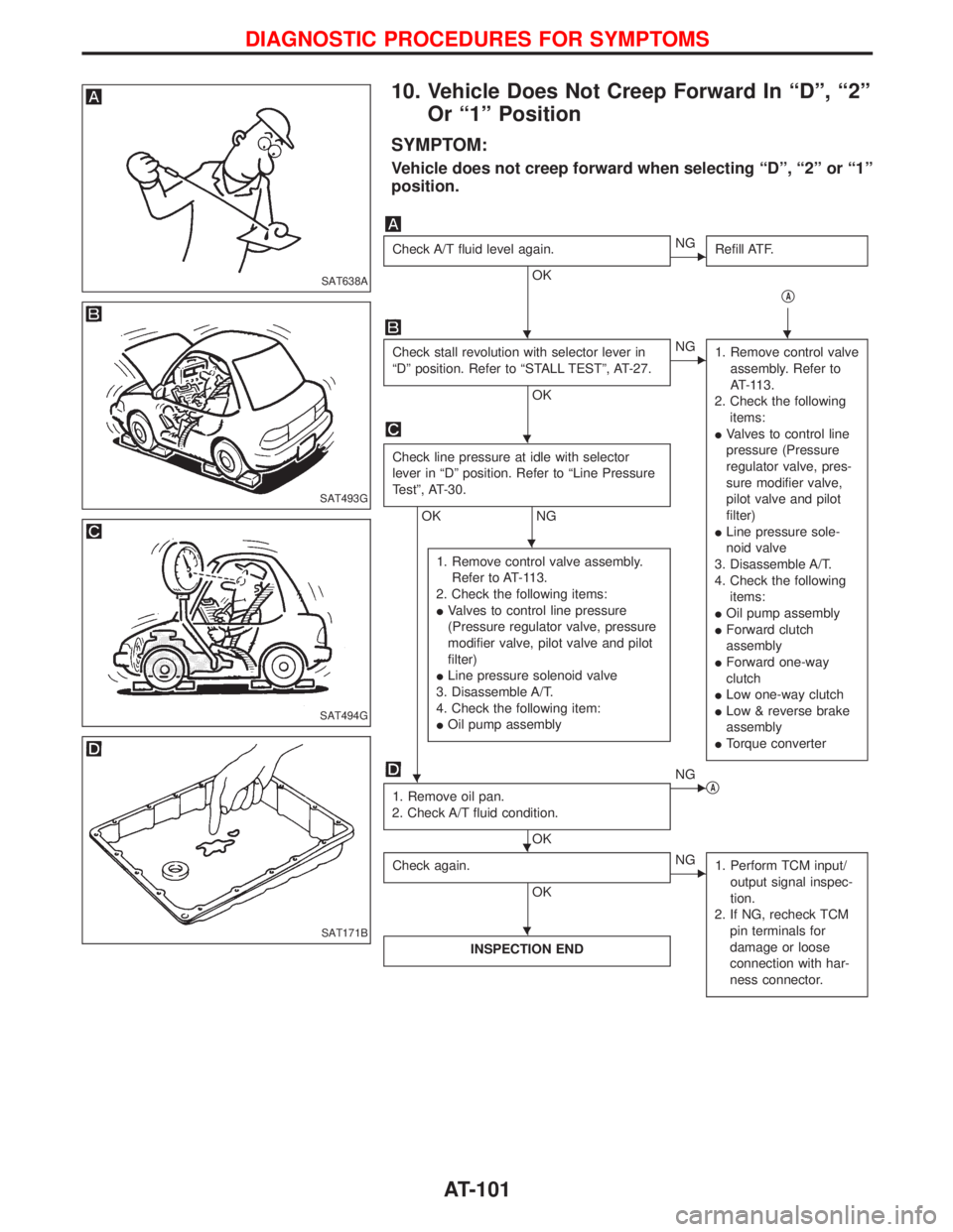
10. Vehicle Does Not Creep Forward In ªDº, ª2º
Or ª1º Position
SYMPTOM:
Vehicle does not creep forward when selecting ªDº, ª2º or ª1º
position.
Check A/T fluid level again.
OK
ENG
Refill ATF.
qA
Check stall revolution with selector lever in
ªDº position. Refer to ªSTALL TESTº, AT-27.
OK
ENG
1. Remove control valve
assembly. Refer to
AT-113.
2. Check the following
items:
IValves to control line
pressure (Pressure
regulator valve, pres-
sure modifier valve,
pilot valve and pilot
filter)
ILine pressure sole-
noid valve
3. Disassemble A/T.
4. Check the following
items:
IOil pump assembly
IForward clutch
assembly
IForward one-way
clutch
ILow one-way clutch
ILow & reverse brake
assembly
ITorque converter
Check line pressure at idle with selector
lever in ªDº position. Refer to ªLine Pressure
Testº, AT-30.
OK NG
1. Remove control valve assembly.
Refer to AT-113.
2. Check the following items:
IValves to control line pressure
(Pressure regulator valve, pressure
modifier valve, pilot valve and pilot
filter)
ILine pressure solenoid valve
3. Disassemble A/T.
4. Check the following item:
IOil pump assembly
1. Remove oil pan.
2. Check A/T fluid condition.
OK
ENG
qA
Check again.
OK
ENG
1. Perform TCM input/
output signal inspec-
tion.
2. If NG, recheck TCM
pin terminals for
damage or loose
connection with har-
ness connector.
INSPECTION END
SAT638A
SAT493G
SAT494G
SAT171B
HH
H
H
H
H H
H
DIAGNOSTIC PROCEDURES FOR SYMPTOMS
AT-101
Page 105 of 1767
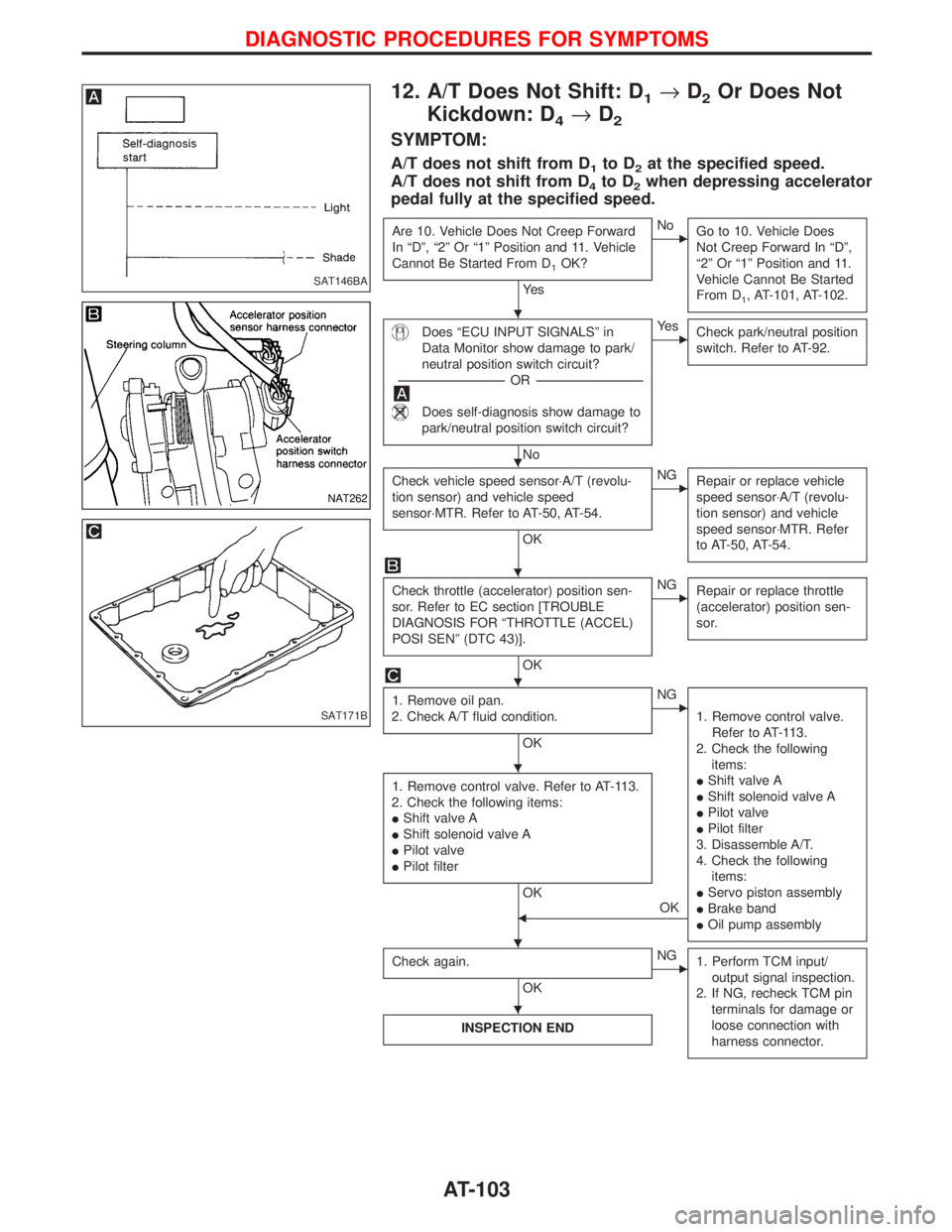
12. A/T Does Not Shift: D1®D2Or Does Not
Kickdown: D
4®D2
SYMPTOM:
A/T does not shift from D1to D2at the specified speed.
A/T does not shift from D
4to D2when depressing accelerator
pedal fully at the specified speed.
Are 10. Vehicle Does Not Creep Forward
In ªDº, ª2º Or ª1º Position and 11. Vehicle
Cannot Be Started From D
1OK?
Ye s
ENo
Go to 10. Vehicle Does
Not Creep Forward In ªDº,
ª2º Or ª1º Position and 11.
Vehicle Cannot Be Started
From D
1, AT-101, AT-102.
Does ªECU INPUT SIGNALSº in
Data Monitor show damage to park/
neutral position switch circuit?
-----------------------------------------------------------------------------------------------------------------------OR -----------------------------------------------------------------------------------------------------------------------
Does self-diagnosis show damage to
park/neutral position switch circuit?
No
EYe s
Check park/neutral position
switch. Refer to AT-92.
Check vehicle speed sensor×A/T (revolu-
tion sensor) and vehicle speed
sensor×MTR. Refer to AT-50, AT-54.
OK
ENG
Repair or replace vehicle
speed sensor×A/T (revolu-
tion sensor) and vehicle
speed sensor×MTR. Refer
to AT-50, AT-54.
Check throttle (accelerator) position sen-
sor. Refer to EC section [TROUBLE
DIAGNOSIS FOR ªTHROTTLE (ACCEL)
POSI SENº (DTC 43)].
OK
ENG
Repair or replace throttle
(accelerator) position sen-
sor.
1. Remove oil pan.
2. Check A/T fluid condition.
OK
ENG
1. Remove control valve.
Refer to AT-113.
2. Check the following
items:
IShift valve A
IShift solenoid valve A
IPilot valve
IPilot filter
3. Disassemble A/T.
4. Check the following
items:
IServo piston assembly
IBrake band
IOil pump assembly
1. Remove control valve. Refer to AT-113.
2. Check the following items:
IShift valve A
IShift solenoid valve A
IPilot valve
IPilot filter
OK
FOK
Check again.
OK
ENG
1. Perform TCM input/
output signal inspection.
2. If NG, recheck TCM pin
terminals for damage or
loose connection with
harness connector.
INSPECTION END
SAT146BA
NAT262
SAT171B
H
H
H
H
H
H H
H
DIAGNOSTIC PROCEDURES FOR SYMPTOMS
AT-103
Page 107 of 1767
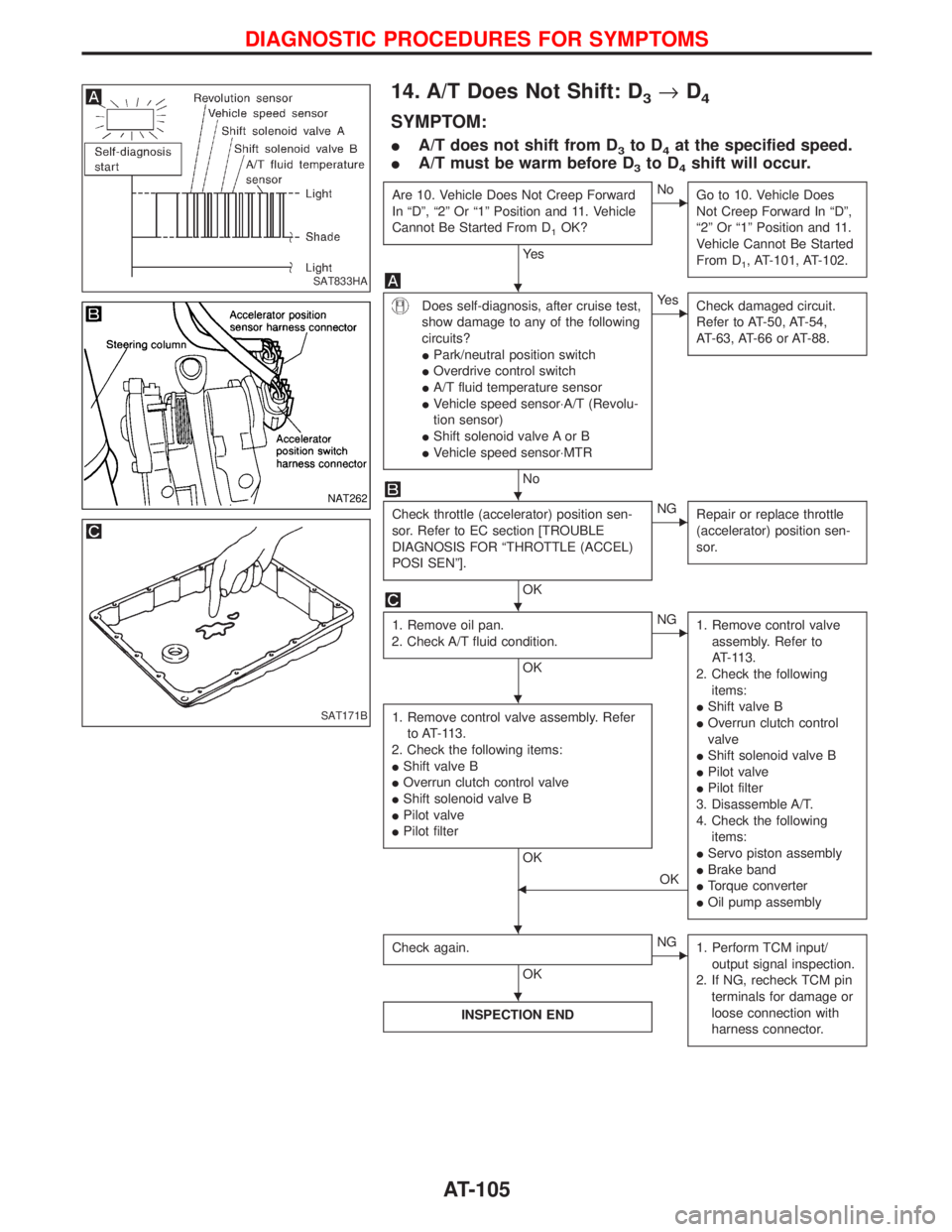
14. A/T Does Not Shift: D3®D4
SYMPTOM:
IA/T does not shift from D3to D4at the specified speed.
IA/T must be warm before D
3to D4shift will occur.
Are 10. Vehicle Does Not Creep Forward
In ªDº, ª2º Or ª1º Position and 11. Vehicle
Cannot Be Started From D
1OK?
Ye s
ENo
Go to 10. Vehicle Does
Not Creep Forward In ªDº,
ª2º Or ª1º Position and 11.
Vehicle Cannot Be Started
From D
1, AT-101, AT-102.
Does self-diagnosis, after cruise test,
show damage to any of the following
circuits?
IPark/neutral position switch
IOverdrive control switch
IA/T fluid temperature sensor
IVehicle speed sensor×A/T (Revolu-
tion sensor)
IShift solenoid valve A or B
IVehicle speed sensor×MTR
No
EYe s
Check damaged circuit.
Refer to AT-50, AT-54,
AT-63, AT-66 or AT-88.
Check throttle (accelerator) position sen-
sor. Refer to EC section [TROUBLE
DIAGNOSIS FOR ªTHROTTLE (ACCEL)
POSI SENº].
OK
ENG
Repair or replace throttle
(accelerator) position sen-
sor.
1. Remove oil pan.
2. Check A/T fluid condition.
OK
ENG
1. Remove control valve
assembly. Refer to
AT-113.
2. Check the following
items:
IShift valve B
IOverrun clutch control
valve
IShift solenoid valve B
IPilot valve
IPilot filter
3. Disassemble A/T.
4. Check the following
items:
IServo piston assembly
IBrake band
ITorque converter
IOil pump assembly
1. Remove control valve assembly. Refer
to AT-113.
2. Check the following items:
IShift valve B
IOverrun clutch control valve
IShift solenoid valve B
IPilot valve
IPilot filter
OK
FOK
Check again.
OK
ENG
1. Perform TCM input/
output signal inspection.
2. If NG, recheck TCM pin
terminals for damage or
loose connection with
harness connector.
INSPECTION END
SAT833HA
NAT262
SAT171B
H
H
H
H
H H
H
DIAGNOSTIC PROCEDURES FOR SYMPTOMS
AT-105
Page 110 of 1767
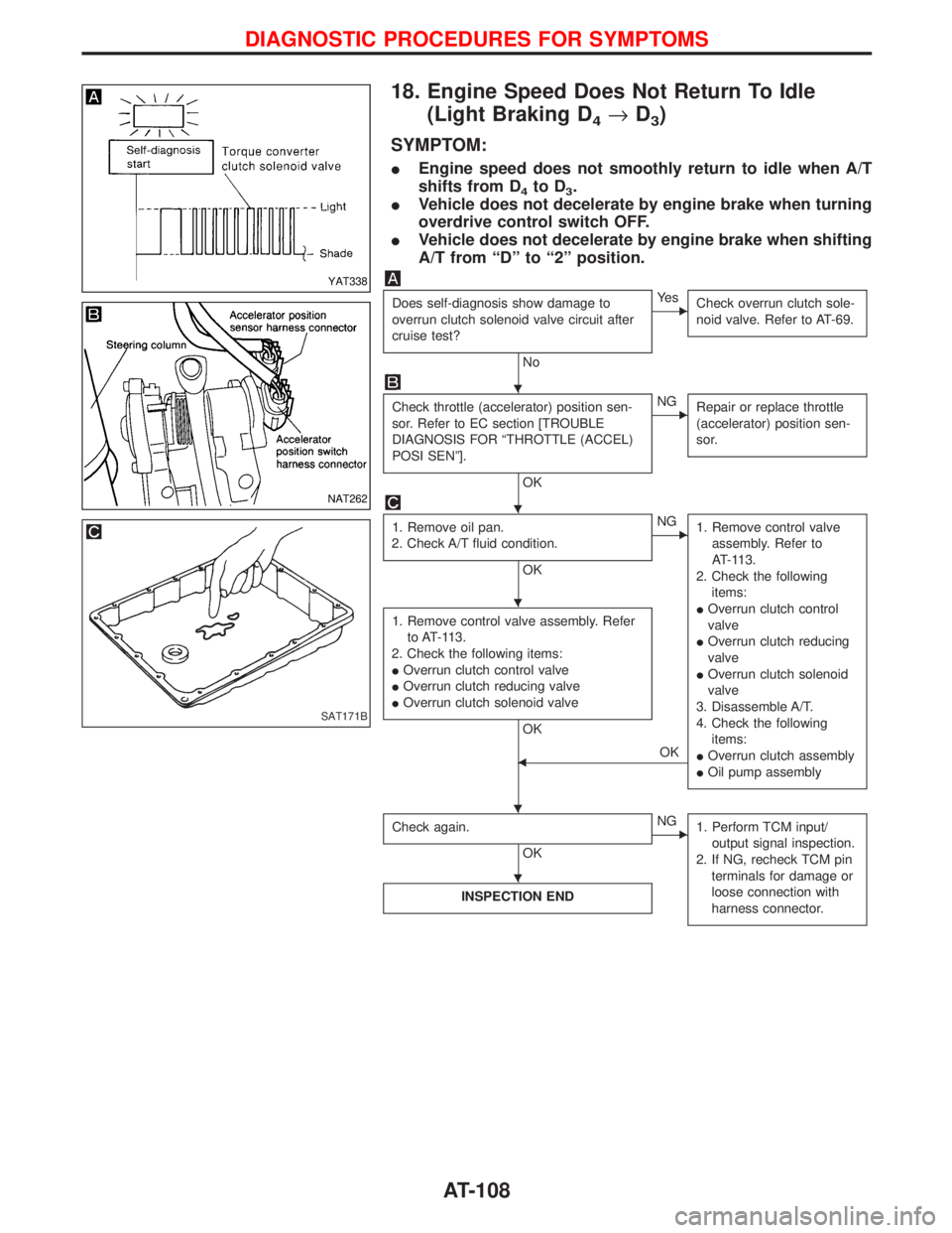
18. Engine Speed Does Not Return To Idle
(Light Braking D
4®D3)
SYMPTOM:
IEngine speed does not smoothly return to idle when A/T
shifts from D
4to D3.
IVehicle does not decelerate by engine brake when turning
overdrive control switch OFF.
IVehicle does not decelerate by engine brake when shifting
A/T from ªDº to ª2º position.
Does self-diagnosis show damage to
overrun clutch solenoid valve circuit after
cruise test?
No
EYe s
Check overrun clutch sole-
noid valve. Refer to AT-69.
Check throttle (accelerator) position sen-
sor. Refer to EC section [TROUBLE
DIAGNOSIS FOR ªTHROTTLE (ACCEL)
POSI SENº].
OK
ENG
Repair or replace throttle
(accelerator) position sen-
sor.
1. Remove oil pan.
2. Check A/T fluid condition.
OK
ENG
1. Remove control valve
assembly. Refer to
AT-113.
2. Check the following
items:
IOverrun clutch control
valve
IOverrun clutch reducing
valve
IOverrun clutch solenoid
valve
3. Disassemble A/T.
4. Check the following
items:
IOverrun clutch assembly
IOil pump assembly
1. Remove control valve assembly. Refer
to AT-113.
2. Check the following items:
IOverrun clutch control valve
IOverrun clutch reducing valve
IOverrun clutch solenoid valve
OK
FOK
Check again.
OK
ENG
1. Perform TCM input/
output signal inspection.
2. If NG, recheck TCM pin
terminals for damage or
loose connection with
harness connector.
INSPECTION END
YAT338
NAT262
SAT171B
H
H
H
H H
H
DIAGNOSTIC PROCEDURES FOR SYMPTOMS
AT-108
Page 112 of 1767
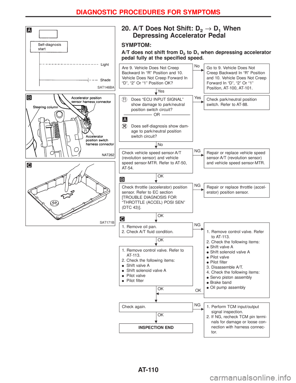
20. A/T Does Not Shift: D2®D1When
Depressing Accelerator Pedal
SYMPTOM:
A/T does not shift from D2to D1when depressing accelerator
pedal fully at the specified speed.
Are 9. Vehicle Does Not Creep
Backward In ªRº Position and 10.
Vehicle Does Not Creep Forward In
ªDº, ª2º Or ª1º Position OK?
Ye s
ENo
Go to 9. Vehicle Does Not
Creep Backward In ªRº Position
and 10. Vehicle Does Not Creep
Forward In ªDº, ª2º Or ª1º
Position, AT-100, AT-101.
Does ªECU INPUT SIGNALº
show damage to park/neutral
position switch circuit?
-----------------------------------------------------------------------------------------------------OR -----------------------------------------------------------------------------------------------------
Does self-diagnosis show dam-
age to park/neutral position
switch circuit?
No
EYe s
Check park/neutral position
switch. Refer to AT-88.
Check vehicle speed sensor×A/T
(revolution sensor) and vehicle
speed sensor×MTR. Refer to AT-50,
AT-54.
OK
ENG
Repair or replace vehicle speed
sensor×A/T (revolution sensor)
and vehicle speed sensor×MTR.
Check throttle (accelerator) position
sensor. Refer to EC section
[TROUBLE DIAGNOSIS FOR
ªTHROTTLE (ACCEL) POSI SENº
(DTC 43)].
OK
ENG
Repair or replace throttle (accel-
erator) position sensor.
1. Remove oil pan.
2. Check A/T fluid condition.
OK
ENG
1. Remove control valve. Refer
to AT-113.
2. Check the following items:
IShift valve A
IShift solenoid valve A
IPilot valve
IPilot filter
3. Disassemble A/T.
4. Check the following items:
IServo piston assembly
IBrake band
IOil pump assembly
1. Remove control valve. Refer to
AT-113.
2. Check the following items:
IShift valve A
IShift solenoid valve A
IPilot valve
IPilot filter
OKFOK
Check again.
OK
ENG
1. Perform TCM input/output
signal inspection.
2. If NG, recheck TCM pin termi-
nals for damage or loose con-
nection with harness connec-
tor.
INSPECTION END
SAT146BA
NAT262
SAT171B
H
H
H
H
H
H
H
DIAGNOSTIC PROCEDURES FOR SYMPTOMS
AT-110
Page 114 of 1767
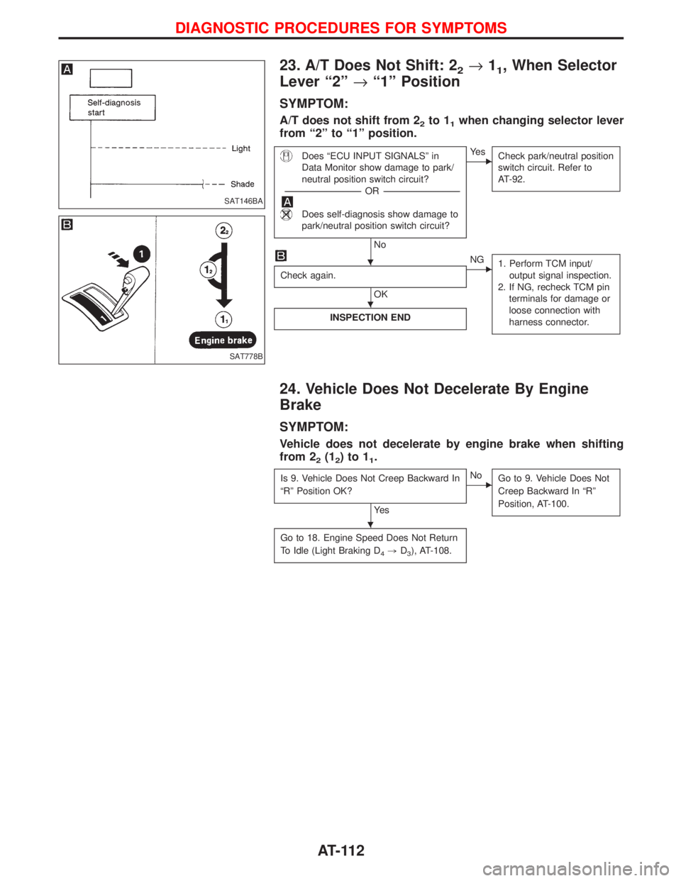
23. A/T Does Not Shift: 22®11, When Selector
Lever ª2º®ª1º Position
SYMPTOM:
A/T does not shift from 22to 11when changing selector lever
from ª2º to ª1º position.
Does ªECU INPUT SIGNALSº in
Data Monitor show damage to park/
neutral position switch circuit?
-----------------------------------------------------------------------------------------------------------------------OR -----------------------------------------------------------------------------------------------------------------------
Does self-diagnosis show damage to
park/neutral position switch circuit?
No
EYe s
Check park/neutral position
switch circuit. Refer to
AT-92.
Check again.
OK
ENG
1. Perform TCM input/
output signal inspection.
2. If NG, recheck TCM pin
terminals for damage or
loose connection with
harness connector.
INSPECTION END
24. Vehicle Does Not Decelerate By Engine
Brake
SYMPTOM:
Vehicle does not decelerate by engine brake when shifting
from 2
2(12)to11.
Is 9. Vehicle Does Not Creep Backward In
ªRº Position OK?
Ye s
ENo
Go to 9. Vehicle Does Not
Creep Backward In ªRº
Position, AT-100.
Go to 18. Engine Speed Does Not Return
To Idle (Light Braking D
4,D3), AT-108.
SAT146BA
SAT778B
H
H
H
DIAGNOSTIC PROCEDURES FOR SYMPTOMS
AT-112
Page 120 of 1767
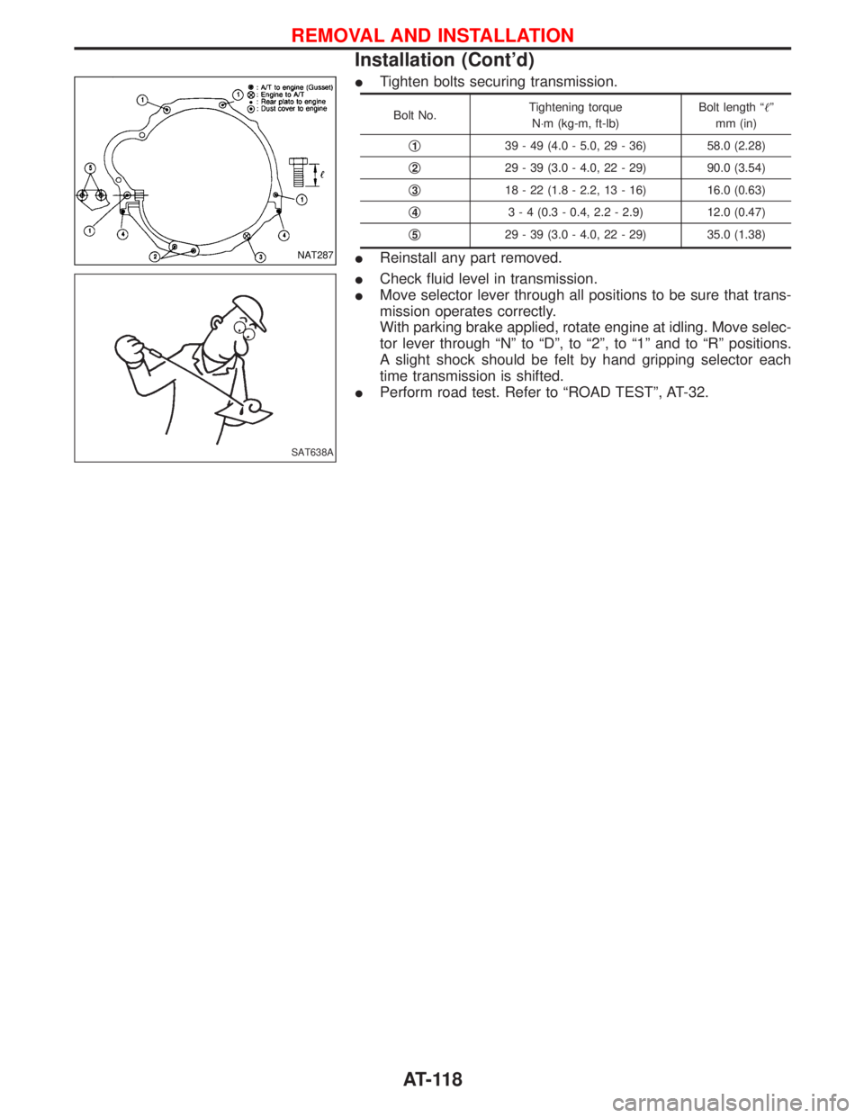
ITighten bolts securing transmission.
Bolt No.Tightening torque
N×m (kg-m, ft-lb)Bolt length ªº
mm (in)
q
139 - 49 (4.0 - 5.0, 29 - 36) 58.0 (2.28)
q
229 - 39 (3.0 - 4.0, 22 - 29) 90.0 (3.54)
q
318 - 22 (1.8 - 2.2, 13 - 16) 16.0 (0.63)
q
43 - 4 (0.3 - 0.4, 2.2 - 2.9) 12.0 (0.47)
q
529 - 39 (3.0 - 4.0, 22 - 29) 35.0 (1.38)
IReinstall any part removed.
ICheck fluid level in transmission.
IMove selector lever through all positions to be sure that trans-
mission operates correctly.
With parking brake applied, rotate engine at idling. Move selec-
tor lever through ªNº to ªDº, to ª2º, to ª1º and to ªRº positions.
A slight shock should be felt by hand gripping selector each
time transmission is shifted.
IPerform road test. Refer to ªROAD TESTº, AT-32.NAT287
SAT638A
REMOVAL AND INSTALLATION
Installation (Cont'd)
AT-118
Page 129 of 1767
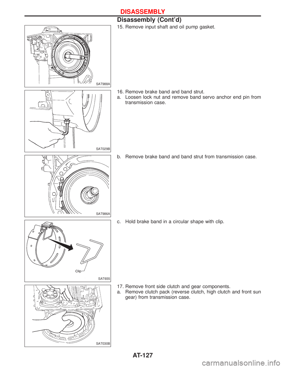
15. Remove input shaft and oil pump gasket.
16. Remove brake band and band strut.
a. Loosen lock nut and remove band servo anchor end pin from
transmission case.
b. Remove brake band and band strut from transmission case.
c. Hold brake band in a circular shape with clip.
17. Remove front side clutch and gear components.
a. Remove clutch pack (reverse clutch, high clutch and front sun
gear) from transmission case.
SAT988A
SAT029B
SAT986A
SAT655
SAT030B
DISASSEMBLY
Disassembly (Cont'd)
AT-127
Page 163 of 1767

Low & Reverse Brake
DISASSEMBLY
1. Check operation of low and reverse brake.
a. Install seal ring onto oil pump cover and install reverse clutch.
Apply compressed air to oil hole.
b. Check to see that retaining plate moves to snap ring.
c. If retaining plate does not contact snap ring,
ID-ring might be damaged.
IOil seal might be damaged.
IFluid might be leaking past piston check ball.
2. Remove snap ring, low and reverse brake drive plates, driven
plates and dish plate.
NAT298
SAT872A
SAT873A
REPAIR FOR COMPONENT PARTS
AT-161
Page 164 of 1767

3. Remove low one-way clutch inner race, spring retainer and
return spring from transmission case.
4. Remove seal rings from low one-way clutch inner race.
5. Remove needle bearing from low one-way clutch inner race.
6. Remove low and reverse brake piston using compressed air.
7. Remove oil seal and D-ring from piston.
INSPECTION
Low and reverse brake snap ring and spring retainer
ICheck for deformation, or damage.
Low and reverse brake return springs
ICheck for deformation or damage. Also measure free length
and outside diameter.
Inspection standard:
Refer to SDS, AT-197.
Low and reverse brake drive plates
ICheck facing for burns, cracks or damage.
IMeasure thickness of facing.
Thickness of drive plate:
Standard value
1.52 - 1.67 mm (0.0598 - 0.0657 in)
Wear limit
1.4 mm (0.055 in)
IIf not within wear limit, replace.
SAT382I
SAT876A
SAT829A
SAT845A
REPAIR FOR COMPONENT PARTS
Low & Reverse Brake (Cont'd)
AT-162