NISSAN TERRANO 2002 Service Repair Manual
Manufacturer: NISSAN, Model Year: 2002, Model line: TERRANO, Model: NISSAN TERRANO 2002Pages: 1767, PDF Size: 41.51 MB
Page 501 of 1767

6 CHECK ACCELERATOR POSITION SENSOR
With CONSULT-II
1. Reconnect all disconnected harness connectors.
2. Turn ignition switch ªONº.
3. Select ªDATA MONITORº mode with CONSULT-II.
4. Check the indication of ªACCEL POS SENº under the following conditions.
SEF818Y
OK or NG
OKEGO TO 7.
NGEReplace accelerator pedal assembly.
7 CHECK ACCELERATOR POSITION SENSOR
Without CONSULT-II
1. Reconnect all disconnected harness connectors.
2. Turn ignition switch ªONº.
3. Check voltage between ECM terminal 23 and ground under the following conditions.
SEF407Y
OK or NG
OKEGO TO 8.
NGEReplace accelerator pedal assembly.
8 RESET ACCELERATOR POSITION SENSOR IDLE POSITION MEMORY
With CONSULT-II
1. Turn ignition switch ªONº.
2. Select ªOFF ACCEL PO SIGº in ªACTIVE TESTº mode with CONSULT-II.
3. Touch ªCLEARº.
EGO TO 9.
DTC 0403 ACCEL POS SENSORZD30DDTi
Diagnostic Procedure (Cont'd)
EC-139
Page 502 of 1767
9 RESET ACCELERATOR POSITION SENSOR IDLE POSITION MEMORY
Without CONSULT-II
1. Start engine and warm it up to normal operating temperature.
2. Let engine idle for 10 minutes.
EGO TO 10.
10 CHECK INTERMITTENT INCIDENT
Refer to ªTROUBLE DIAGNOSIS FOR INTERMITTENT INCIDENTº, EC-78.
EINSPECTION END
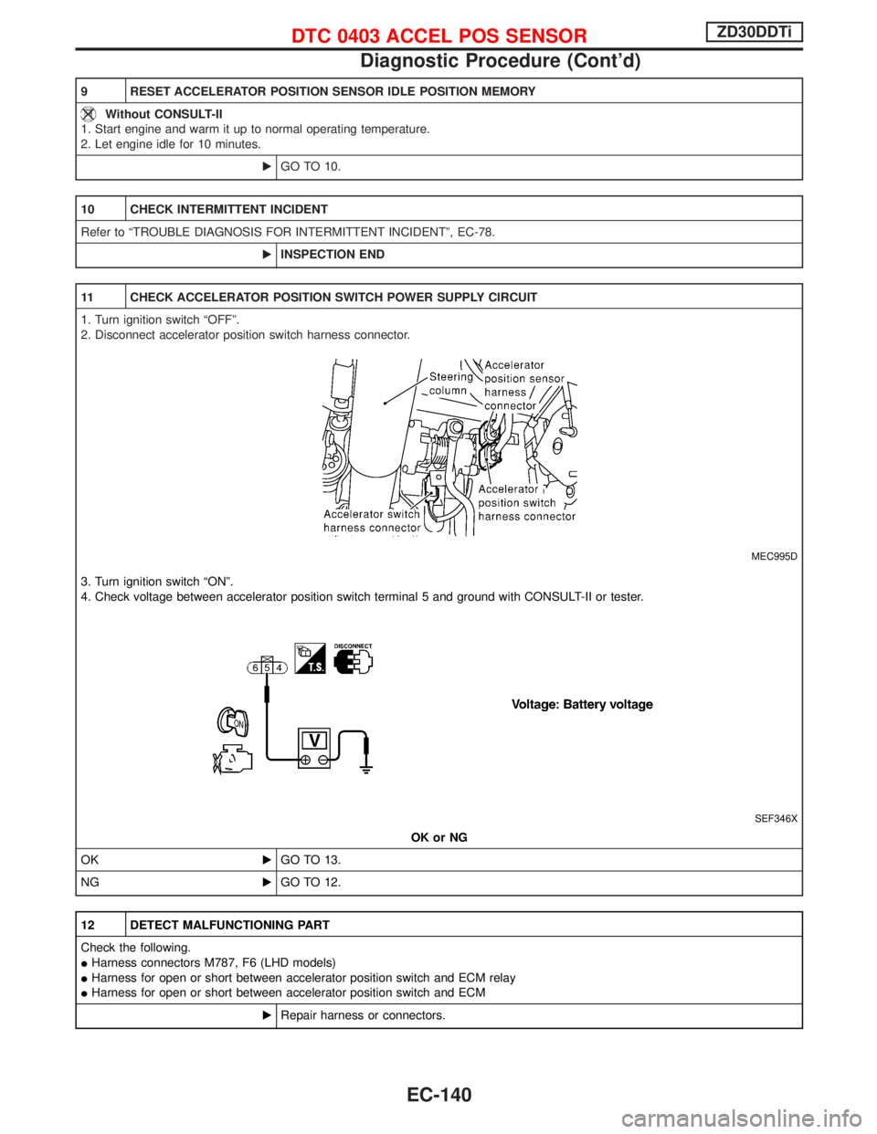
11 CHECK ACCELERATOR POSITION SWITCH POWER SUPPLY CIRCUIT
1. Turn ignition switch ªOFFº.
2. Disconnect accelerator position switch harness connector.
MEC995D
3. Turn ignition switch ªONº.
4. Check voltage between accelerator position switch terminal 5 and ground with CONSULT-II or tester.
SEF346X
OK or NG
OKEGO TO 13.
NGEGO TO 12.
12 DETECT MALFUNCTIONING PART
Check the following.
IHarness connectors M787, F6 (LHD models)
IHarness for open or short between accelerator position switch and ECM relay
IHarness for open or short between accelerator position switch and ECM
ERepair harness or connectors.
DTC 0403 ACCEL POS SENSORZD30DDTi
Diagnostic Procedure (Cont'd)
EC-140
Page 503 of 1767
13 CHECK ACCELERATOR POSITION SWITCH INPUT SIGNAL CIRCUIT-I FOR OPEN AND SHORT
1. Turn ignition switch ªOFFº.
2. Disconnect ECM harness connector.
3. Check harness continuity between accelerator position switch terminal 6 and ECM terminal 31. Refer to Wiring Diagram.
Continuity should exist.
4. Also check harness for short to ground and short to power.
OK or NG
OKEGO TO 14.
NGERepair open circuit or short to ground or short to power in harness or connectors.
14 CHECK ACCELERATOR POSITION SWITCH INPUT SIGNAL CIRCUIT-II FOR OPEN AND SHORT
1. Check harness continuity between accelerator position switch terminal 4 and ECM terminal 32. Refer to Wiring Diagram.
Continuity should exist.
2. Also check harness for short to ground and short to power.
OK or NG
OKEGO TO 15.
NGERepair open circuit or short to ground or short to power in harness or connectors.
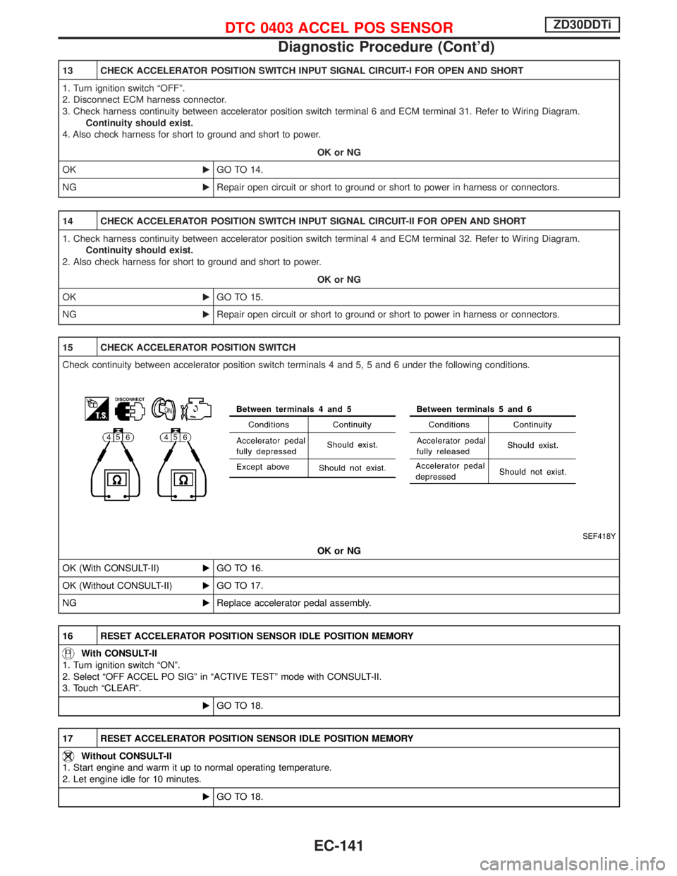
15 CHECK ACCELERATOR POSITION SWITCH
Check continuity between accelerator position switch terminals 4 and 5, 5 and 6 under the following conditions.
SEF418Y
OK or NG
OK (With CONSULT-II)EGO TO 16.
OK (Without CONSULT-II)EGO TO 17.
NGEReplace accelerator pedal assembly.
16 RESET ACCELERATOR POSITION SENSOR IDLE POSITION MEMORY
With CONSULT-II
1. Turn ignition switch ªONº.
2. Select ªOFF ACCEL PO SIGº in ªACTIVE TESTº mode with CONSULT-II.
3. Touch ªCLEARº.
EGO TO 18.
17 RESET ACCELERATOR POSITION SENSOR IDLE POSITION MEMORY
Without CONSULT-II
1. Start engine and warm it up to normal operating temperature.
2. Let engine idle for 10 minutes.
EGO TO 18.
DTC 0403 ACCEL POS SENSORZD30DDTi
Diagnostic Procedure (Cont'd)
EC-141
Page 504 of 1767

18 CHECK INTERMITTENT INCIDENT
Refer to ªTROUBLE DIAGNOSIS FOR INTERMITTENT INCIDENTº, EC-78.
EINSPECTION END
DTC 0403 ACCEL POS SENSORZD30DDTi
Diagnostic Procedure (Cont'd)
EC-142
Page 505 of 1767
On Board Diagnosis Logic
Malfunction is detected when ... Check Items (Possible Cause)
IAn excessively high voltage from the mass air flow sensor is
sent to ECM when engine is running.IAir duct
ICharge air cooler
IVariable nozzle turbocharger control system
IVariable nozzle turbocharger
IMass air flow sensor
IHarness or connectors
(The mass air flow sensor circuit is shorted.)
DTC Confirmation Procedure
NOTE:
If DTC 0406 ªINT AIR VOLº displayed with DTC 0102 ªMASS
AIR FLOW SENº, perform trouble diagnosis for DTC 0102
ªMASS AIR FLOW SENº first. (See EC-88.)
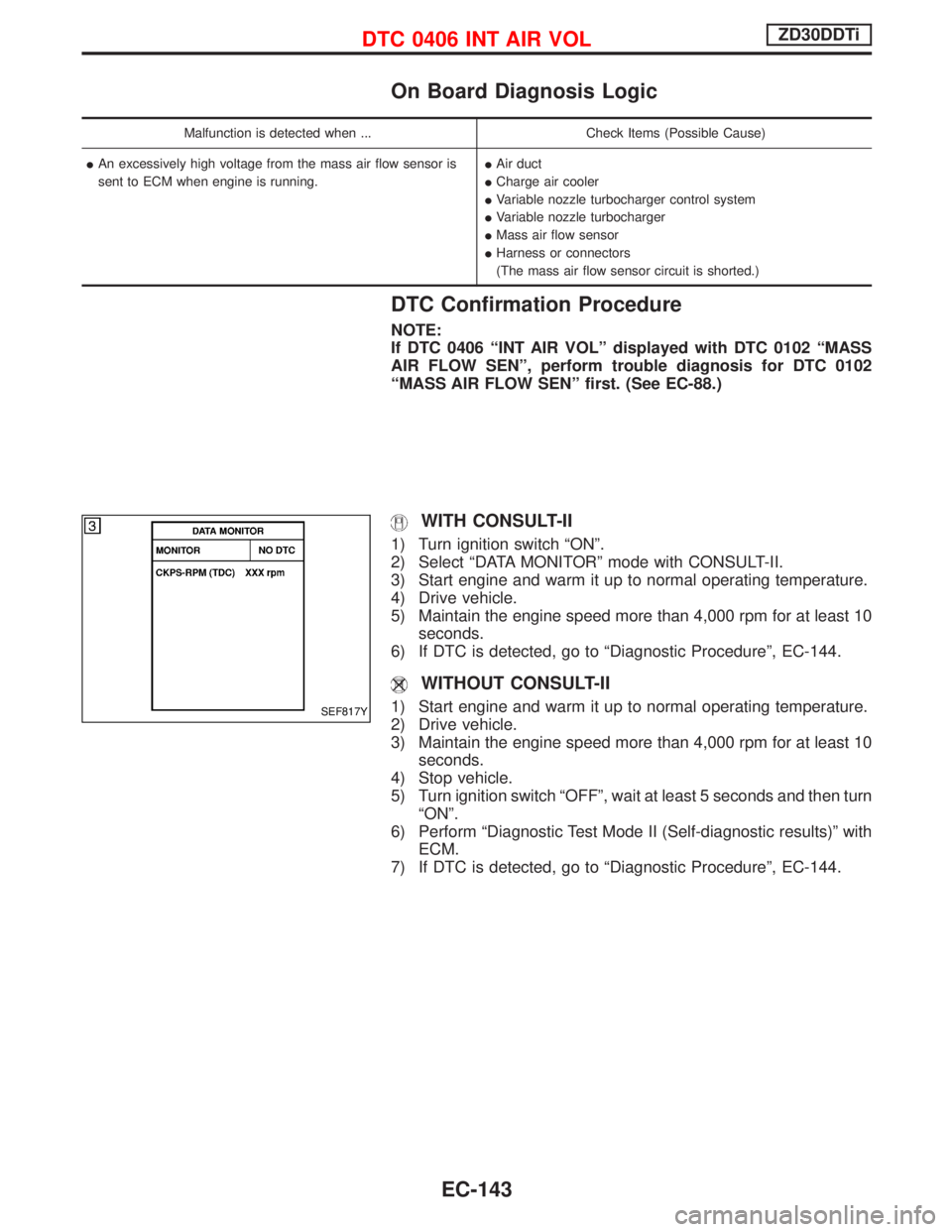
WITH CONSULT-II
1) Turn ignition switch ªONº.
2) Select ªDATA MONITORº mode with CONSULT-II.
3) Start engine and warm it up to normal operating temperature.
4) Drive vehicle.
5) Maintain the engine speed more than 4,000 rpm for at least 10
seconds.
6) If DTC is detected, go to ªDiagnostic Procedureº, EC-144.
WITHOUT CONSULT-II
1) Start engine and warm it up to normal operating temperature.
2) Drive vehicle.
3) Maintain the engine speed more than 4,000 rpm for at least 10
seconds.
4) Stop vehicle.
5) Turn ignition switch ªOFFº, wait at least 5 seconds and then turn
ªONº.
6) Perform ªDiagnostic Test Mode II (Self-diagnostic results)º with
ECM.
7) If DTC is detected, go to ªDiagnostic Procedureº, EC-144.SEF817Y
DTC 0406 INT AIR VOLZD30DDTi
EC-143
Page 506 of 1767
Diagnostic Procedure
1 CHECK INTAKE AIR LEAK
Listen for an intake air leak after the mass air flow sensor.
OK or NG
OKEGO TO 2.
NGERepair or replace.
2 CHECK VARIABLE NOZZLE TURBOCHARGER OVERALL FUNCTION
1. Start engine and let it idle.
2. Make sure that variable nozzle turbocharger control actuator rod moves when revving engine up to 3,000 rpm and returning to
idle.
MEC015E
OK or NG
OKEGO TO 3.
NGEGo to ªDiagnostic Procedureº in ªVARIABLE NOZZLE TURBOCHARGER CONTROL SOLE-
NOID VALVEº, EC-284.
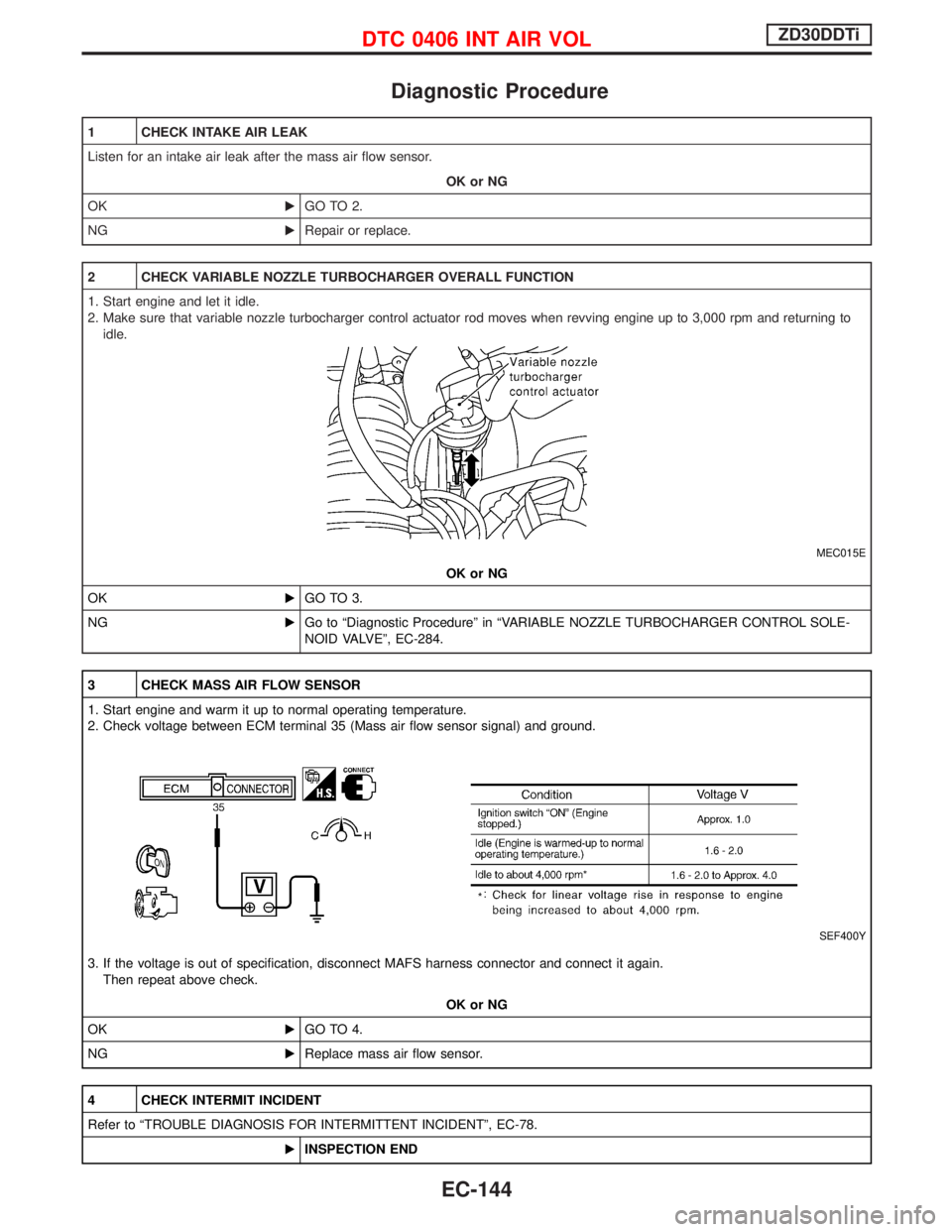
3 CHECK MASS AIR FLOW SENSOR
1. Start engine and warm it up to normal operating temperature.
2. Check voltage between ECM terminal 35 (Mass air flow sensor signal) and ground.
SEF400Y
3. If the voltage is out of specification, disconnect MAFS harness connector and connect it again.
Then repeat above check.
OK or NG
OKEGO TO 4.
NGEReplace mass air flow sensor.
4 CHECK INTERMIT INCIDENT
Refer to ªTROUBLE DIAGNOSIS FOR INTERMITTENT INCIDENTº, EC-78.
EINSPECTION END
DTC 0406 INT AIR VOLZD30DDTi
EC-144
Page 507 of 1767
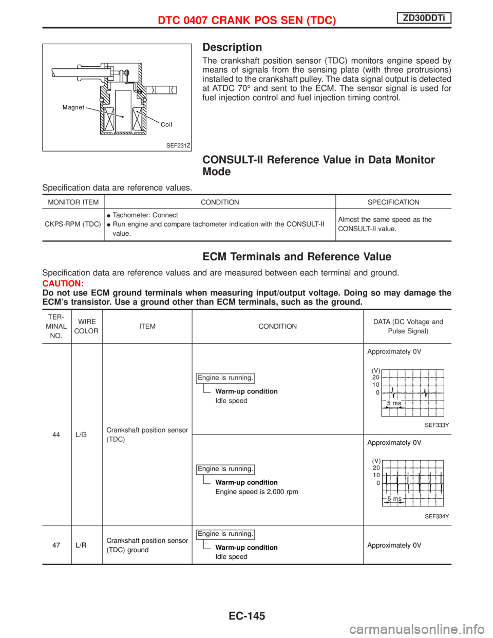
Description
The crankshaft position sensor (TDC) monitors engine speed by
means of signals from the sensing plate (with three protrusions)
installed to the crankshaft pulley. The data signal output is detected
at ATDC 70É and sent to the ECM. The sensor signal is used for
fuel injection control and fuel injection timing control.
CONSULT-II Reference Value in Data Monitor
Mode
Specification data are reference values.
MONITOR ITEM CONDITION SPECIFICATION
CKPS×RPM (TDC)ITachometer: Connect
IRun engine and compare tachometer indication with the CONSULT-II
value.Almost the same speed as the
CONSULT-II value.
ECM Terminals and Reference Value
Specification data are reference values and are measured between each terminal and ground.
CAUTION:
Do not use ECM ground terminals when measuring input/output voltage. Doing so may damage the
ECM's transistor. Use a ground other than ECM terminals, such as the ground.
TER-
MINAL
NO.WIRE
COLORITEM CONDITIONDATA (DC Voltage and
Pulse Signal)
44 L/GCrankshaft position sensor
(TDC)Engine is running.
Warm-up condition
Idle speedApproximately 0V
SEF333Y
Engine is running.
Warm-up condition
Engine speed is 2,000 rpmApproximately 0V
SEF334Y
47 L/RCrankshaft position sensor
(TDC) groundEngine is running.Warm-up condition
Idle speedApproximately 0V
SEF231Z
DTC 0407 CRANK POS SEN (TDC)ZD30DDTi
EC-145
Page 508 of 1767
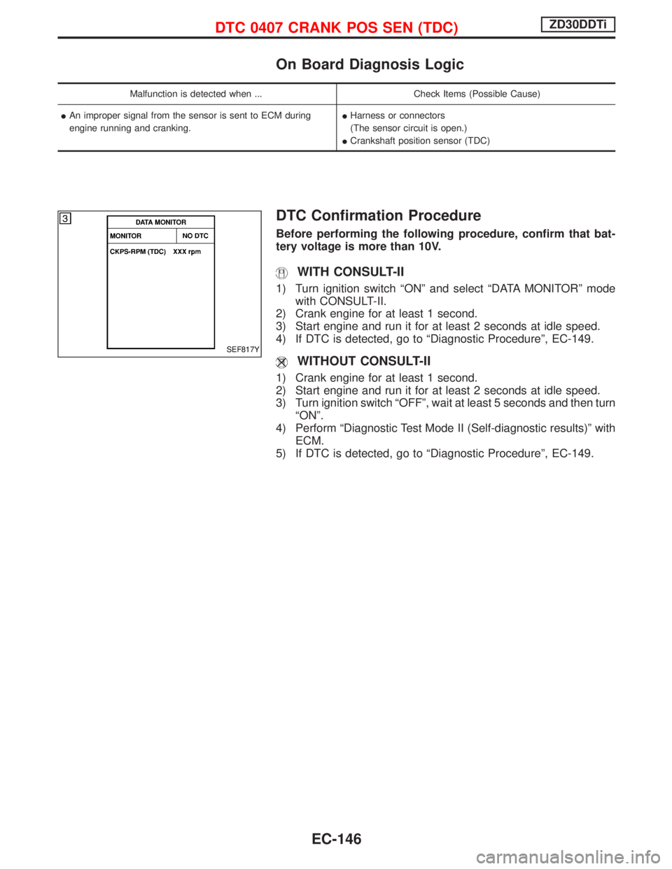
On Board Diagnosis Logic
Malfunction is detected when ... Check Items (Possible Cause)
IAn improper signal from the sensor is sent to ECM during
engine running and cranking.IHarness or connectors
(The sensor circuit is open.)
ICrankshaft position sensor (TDC)
DTC Confirmation Procedure
Before performing the following procedure, confirm that bat-
tery voltage is more than 10V.
WITH CONSULT-II
1) Turn ignition switch ªONº and select ªDATA MONITORº mode
with CONSULT-II.
2) Crank engine for at least 1 second.
3) Start engine and run it for at least 2 seconds at idle speed.
4) If DTC is detected, go to ªDiagnostic Procedureº, EC-149.
WITHOUT CONSULT-II
1) Crank engine for at least 1 second.
2) Start engine and run it for at least 2 seconds at idle speed.
3) Turn ignition switch ªOFFº, wait at least 5 seconds and then turn
ªONº.
4) Perform ªDiagnostic Test Mode II (Self-diagnostic results)º with
ECM.
5) If DTC is detected, go to ªDiagnostic Procedureº, EC-149.
SEF817Y
DTC 0407 CRANK POS SEN (TDC)ZD30DDTi
EC-146
Page 509 of 1767

Wiring Diagram
LHD MODELS
YEC185A
DTC 0407 CRANK POS SEN (TDC)ZD30DDTi
EC-147
Page 510 of 1767

RHD MODELS
YEC186A
DTC 0407 CRANK POS SEN (TDC)ZD30DDTi
Wiring Diagram (Cont'd)
EC-148