NISSAN TERRANO 2002 Service Repair Manual
Manufacturer: NISSAN, Model Year: 2002, Model line: TERRANO, Model: NISSAN TERRANO 2002Pages: 1767, PDF Size: 41.51 MB
Page 731 of 1767
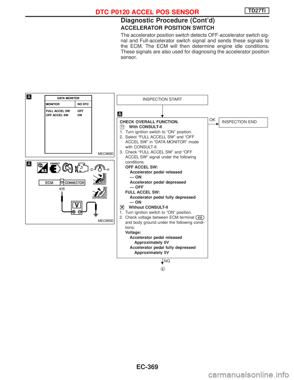
ACCELERATOR POSITION SWITCH
The accelerator position switch detects OFF-accelerator switch sig-
nal and Full-accelerator switch signal and sends these signals to
the ECM. The ECM will then determine engine idle conditions.
These signals are also used for diagnosing the accelerator position
sensor.
INSPECTION START
CHECK OVERALL FUNCTION.
With CONSULT-II
1. Turn ignition switch to ªONº position.
2. Select ªFULL ACCELL SWº and ªOFF
ACCEL SWº in ªDATA MONITORº mode
with CONSULT-II.
3. Check ªFULL ACCEL SWº and ªOFF
ACCEL SWº signal under the following
conditions.
OFF ACCEL SW:
Accelerator pedal released
ÐON
Accelerator pedal depressed
Ð OFF
FULL ACCEL SW:
Accelerator pedal fully depressed
ÐON
Without CONSULT-II
1. Turn ignition switch to ªONº position.
2. Check voltage between ECM terminal
435
and body ground under the following condi-
tions:
Voltage:
Accelerator pedal released
Approximately 0V
Accelerator pedal fully depressed
Approximately 5V
NG
EOK
INSPECTION END
qA
MEC969D
MEC955D
H
H
DTC P0120 ACCEL POS SENSORTD27Ti
Diagnostic Procedure (Cont'd)
EC-369
Page 732 of 1767
qA
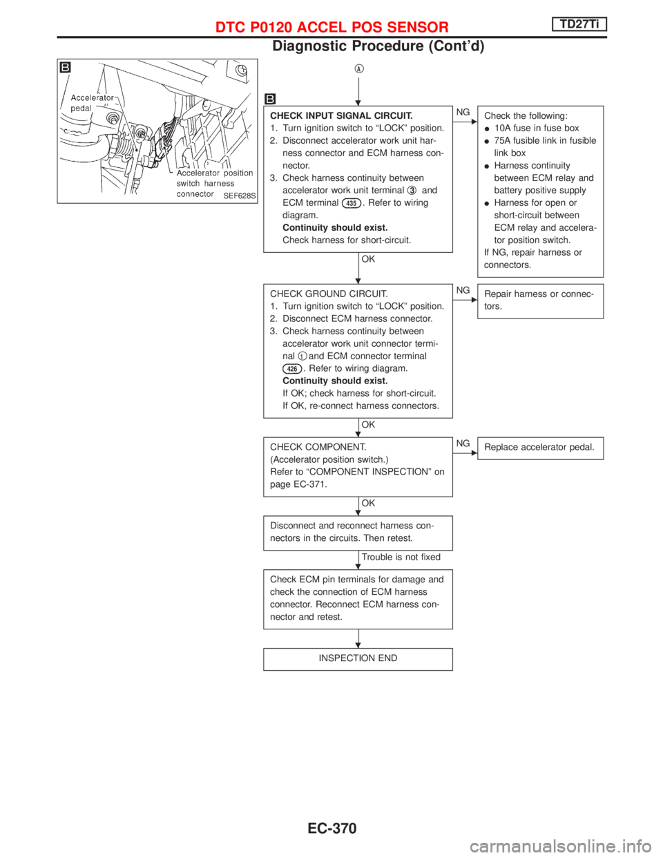
CHECK INPUT SIGNAL CIRCUIT.
1. Turn ignition switch to ªLOCKº position.
2. Disconnect accelerator work unit har-
ness connector and ECM harness con-
nector.
3. Check harness continuity between
accelerator work unit terminalq
3and
ECM terminal
435. Refer to wiring
diagram.
Continuity should exist.
Check harness for short-circuit.
OK
ENG
Check the following:
I10A fuse in fuse box
I75A fusible link in fusible
link box
IHarness continuity
between ECM relay and
battery positive supply
IHarness for open or
short-circuit between
ECM relay and accelera-
tor position switch.
If NG, repair harness or
connectors.
CHECK GROUND CIRCUIT.
1. Turn ignition switch to ªLOCKº position.
2. Disconnect ECM harness connector.
3. Check harness continuity between
accelerator work unit connector termi-
nalq
1and ECM connector terminal
426. Refer to wiring diagram.
Continuity should exist.
If OK; check harness for short-circuit.
If OK, re-connect harness connectors.
OK
ENG
Repair harness or connec-
tors.
CHECK COMPONENT.
(Accelerator position switch.)
Refer to ªCOMPONENT INSPECTIONº on
page EC-371.
OK
ENG
Replace accelerator pedal.
Disconnect and reconnect harness con-
nectors in the circuits. Then retest.
Trouble is not fixed
Check ECM pin terminals for damage and
check the connection of ECM harness
connector. Reconnect ECM harness con-
nector and retest.
INSPECTION END
SEF628S
H
H
H
H
H
H
DTC P0120 ACCEL POS SENSORTD27Ti
Diagnostic Procedure (Cont'd)
EC-370
Page 733 of 1767
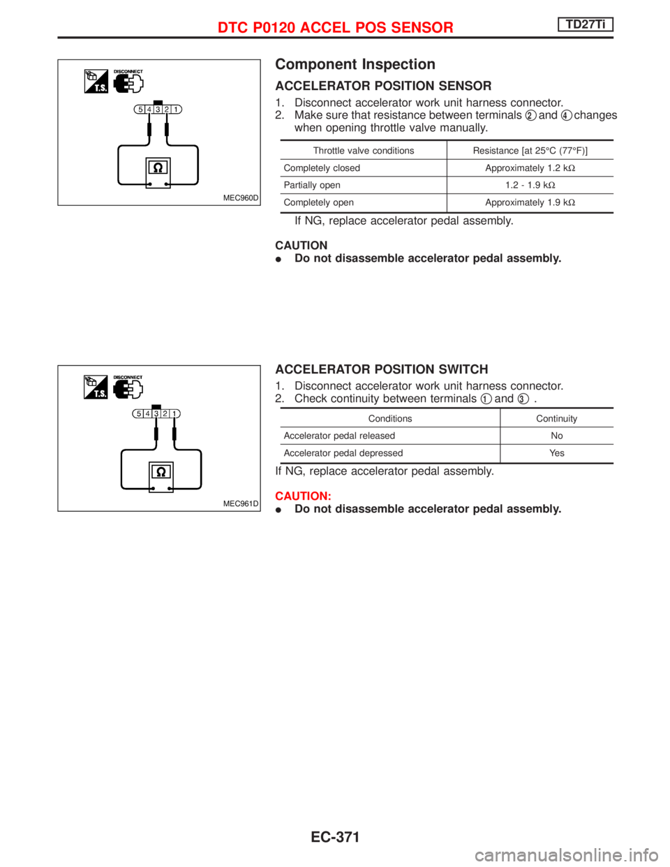
Component Inspection
ACCELERATOR POSITION SENSOR
1. Disconnect accelerator work unit harness connector.
2. Make sure that resistance between terminalsq
2andq4changes
when opening throttle valve manually.
Throttle valve conditions Resistance [at 25ÉC (77ÉF)]
Completely closed Approximately 1.2 kW
Partially open 1.2 - 1.9 kW
Completely open Approximately 1.9 kW
If NG, replace accelerator pedal assembly.
CAUTION
IDo not disassemble accelerator pedal assembly.
ACCELERATOR POSITION SWITCH
1. Disconnect accelerator work unit harness connector.
2. Check continuity between terminalsq
1andq3.
Conditions Continuity
Accelerator pedal released No
Accelerator pedal depressed Yes
If NG, replace accelerator pedal assembly.
CAUTION:
IDo not disassemble accelerator pedal assembly.
MEC960D
MEC961D
DTC P0120 ACCEL POS SENSORTD27Ti
EC-371
Page 734 of 1767
Component Description
FUEL TEMPERATURE SENSOR (FTS)
The fuel temperature sensor is used to detect the fuel temperature
in the injection pump. The sensor modifies a voltage signal from the
ECM. The modified signal returns to the ECM as the fuel tempera-
ture input. The sensor uses a thermistor which is sensitive to the
change in temperature. The electrical resistance of the thermistor
decreases as temperature increases.
The sensor is built into the inside electrical circuit of the injection
pump.
On Board Diagnosis Logic
DTC Malfunction is detected when ...Check Items
(Possible Cause)
P0180
0402IAn excessively high or low voltage from the sensor is
detected by ECM.IHarness or connectors
(The sensor circuit is open or short-circuited.)
IFuel temperature sensor
DTC Confirmation Procedure
WITH CONSULT-II
1) Turn ignition switch to ªONº position.
2) Select ªDATA MONITORº mode with CONSULT-II.
3) Wait at least 5 seconds.
WITHOUT CONSULT-II
1) Turn ignition switch to ªONº position and wait at least 5 sec-
onds.
2) Turn ignition switch to ªLOCKº position, wait at least 5 seconds
and then turn to ªONº position.
3) Perform ªDiagnostic Test Mode IIº (Self-diagnostic results).
DTC P0180 FUEL TEMP SENSORTD27Ti
EC-372
Page 735 of 1767

Wiring Diagram
YEC149A
DTC P0180 FUEL TEMP SENSORTD27Ti
EC-373
Page 736 of 1767
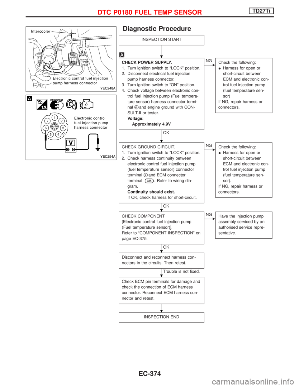
Diagnostic Procedure
INSPECTION START
CHECK POWER SUPPLY.
1. Turn ignition switch to ªLOCKº position.
2. Disconnect electrical fuel injection
pump harness connector.
3. Turn ignition switch to ªONº position.
4. Check voltage between electronic con-
trol fuel injection pump (Fuel tempera-
ture sensor) harness connector termi-
nalq
6and engine ground with CON-
SULT-II or tester.
Voltage:
Approximately 4.9V
OK
ENG
Check the following:
IHarness for open or
short-circuit between
ECM and electronic con-
trol fuel injection pump
(fuel temperature sen-
sor)
If NG, repair harness or
connectors.
CHECK GROUND CIRCUIT.
1. Turn ignition switch to ªLOCKº position.
2. Check harness continuity between
electronic control fuel injection pump
(fuel temperature sensor) connector
terminalq
5and ECM connector
terminal
335. Refer to wiring dia-
gram.
Continuity should exist.
If OK, check harness for short-circuit.
OK
ENG
Check the following:
IHarness for open or
short-circuit between
ECM and electronic con-
trol fuel injection pump
(fuel temperature sen-
sor).
If NG, repair harness or
connectors.
CHECK COMPONENT
[Electronic control fuel injection pump
(Fuel temperature sensor)].
Refer to ªCOMPONENT INSPECTIONº on
page EC-375.
OK
ENG
Have the injection pump
assembly serviced by an
authorised service repre-
sentative.
Disconnect and reconnect harness con-
nectors in the circuits. Then retest.
Trouble is not fixed.
Check ECM pin terminals for damage and
check the connection of ECM harness
connector. Reconnect ECM harness con-
nector and retest.
INSPECTION END
YEC248A
YEC254A
H
H
H
H
H
H
DTC P0180 FUEL TEMP SENSORTD27Ti
EC-374
Page 737 of 1767

Component Inspection
ELECTRONIC CONTROL FUEL INJECTION PUMP (FUEL
TEMPERATURE SENSOR)
Wait until fuel temperature sensor reaches room temperature.
Check resistance between electronic control fuel injection pump
(fuel temperature sensor) terminalsq
5andq6.
Temperature ÉC (ÉF) Resistance kW
25 (77) Approximately 1.9
If NG, have the injection pump assembly serviced by an authorised
service representative.
YEC255A
DTC P0180 FUEL TEMP SENSORTD27Ti
EC-375
Page 738 of 1767
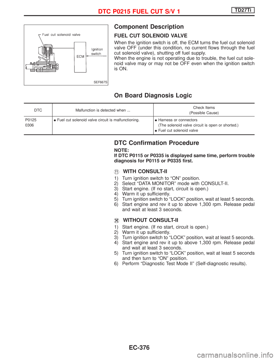
Component Description
FUEL CUT SOLENOID VALVE
When the ignition switch is off, the ECM turns the fuel cut solenoid
valve OFF (under this condition, no current flows through the fuel
cut solenoid valve), shutting off fuel supply.
When the engine is not operating due to trouble, the fuel cut sole-
noid valve may or may not be OFF even when the ignition switch
is ON.
On Board Diagnosis Logic
DTC Malfunction is detected when ...Check Items
(Possible Cause)
P0125
0306IFuel cut solenoid valve circuit is malfunctioning.IHarness or connectors
(The solenoid valve circuit is open or shorted.)
IFuel cut solenoid valve
DTC Confirmation Procedure
NOTE:
If DTC P0115 or P0335 is displayed same time, perform trouble
diagnosis for P0115 or P0335 first.
WITH CONSULT-II
1) Turn ignition switch to ªONº position.
2) Select ªDATA MONITORº mode with CONSULT-II.
3) Start engine. (If no start, circuit is open.)
4) Warm it up sufficiently.
5) Turn ignition switch to ªLOCKº position, wait at least 5 seconds.
6) Start engine and rev it up to above 1,300 rpm. Release pedal
and wait at least 3 seconds.
WITHOUT CONSULT-II
1) Start engine. (If no start, circuit is open.)
2) Warm it up sufficiently.
3) Turn ignition switch to ªLOCKº position, wait at least 5 seconds.
4) Start engine and rev it up to above 1,300 rpm. Release pedal
and wait at least 3 seconds.
5) Turn ignition switch to ªLOCKº position, wait at least 5 seconds
and then turn to ªONº position.
6) Perform ªDiagnostic Test Mode IIº (Self-diagnostic results).
SEF667S
DTC P0215 FUEL CUT S/V 1TD27Ti
EC-376
Page 739 of 1767

Wiring Diagram
YEC158A
DTC P0215 FUEL CUT S/V 1TD27Ti
EC-377
Page 740 of 1767
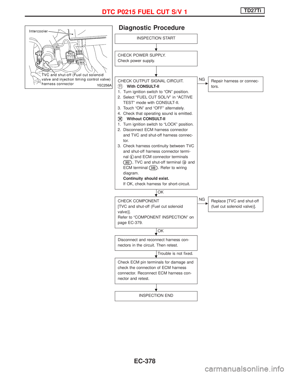
Diagnostic Procedure
INSPECTION START
CHECK POWER SUPPLY.
Check power supply.
CHECK OUTPUT SIGNAL CIRCUIT.
With CONSULT-II
1. Turn ignition switch to ªONº position.
2. Select ªFUEL CUT SOL/Vº in ªACTIVE
TESTº mode with CONSULT-II.
3. Touch ªONº and ªOFFº alternately.
4. Check that operating sound is emitted.
Without CONSULT-II
1. Turn ignition switch to ªLOCKº position.
2. Disconnect ECM harness connector
and TVC and shut-off harness connec-
tor.
3. Check harness continuity between TVC
and shut-off harness connector termi-
nalq
8and ECM connector terminals
202, TVC and shut-off terminalq10and
ECM terminal
349. Refer to wiring
diagram.
Continuity should exist.
If OK, check harness for short-circuit.
OK
ENG
Repair harness or connec-
tors.
CHECK COMPONENT
[TVC and shut-off (Fuel cut solenoid
valve)].
Refer to ªCOMPONENT INSPECTIONº on
page EC-379.
OK
ENG
Replace [TVC and shut-off
(fuel cut solenoid valve)].
Disconnect and reconnect harness con-
nectors in the circuit. Then retest.
Trouble is not fixed.
Check ECM pin terminals for damage and
check the connection of ECM harness
connector. Reconnect ECM harness con-
nector and retest.
INSPECTION END
YEC256A
H
H
H
H
H
H
DTC P0215 FUEL CUT S/V 1TD27Ti
EC-378