NISSAN TERRANO 2002 Service Repair Manual
Manufacturer: NISSAN, Model Year: 2002, Model line: TERRANO, Model: NISSAN TERRANO 2002Pages: 1767, PDF Size: 41.51 MB
Page 701 of 1767
qA
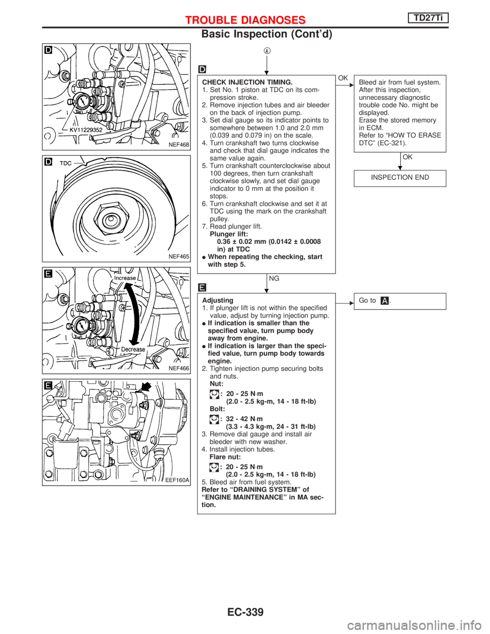
CHECK INJECTION TIMING.
1. Set No. 1 piston at TDC on its com-
pression stroke.
2. Remove injection tubes and air bleeder
on the back of injection pump.
3. Set dial gauge so its indicator points to
somewhere between 1.0 and 2.0 mm
(0.039 and 0.079 in) on the scale.
4. Turn crankshaft two turns clockwise
and check that dial gauge indicates the
same value again.
5. Turn crankshaft counterclockwise about
100 degrees, then turn crankshaft
clockwise slowly, and set dial gauge
indicator to 0 mm at the position it
stops.
6. Turn crankshaft clockwise and set it at
TDC using the mark on the crankshaft
pulley.
7. Read plunger lift.
Plunger lift:
0.36 0.02 mm (0.0142 0.0008
in) at TDC
IWhen repeating the checking, start
with step 5.
NG
EOK
Bleed air from fuel system.
After this inspection,
unnecessary diagnostic
trouble code No. might be
displayed.
Erase the stored memory
in ECM.
Refer to ªHOW TO ERASE
DTCº (EC-321).
OK
INSPECTION END
Adjusting
1. If plunger lift is not within the specified
value, adjust by turning injection pump.
IIf indication is smaller than the
specified value, turn pump body
away from engine.
IIf indication is larger than the speci-
fied value, turn pump body towards
engine.
2. Tighten injection pump securing bolts
and nuts.
Nut:
: 20-25N×m
(2.0 - 2.5 kg-m, 14 - 18 ft-lb)
Bolt:
: 32-42N×m
(3.3 - 4.3 kg-m, 24 - 31 ft-lb)
3. Remove dial gauge and install air
bleeder with new washer.
4. Install injection tubes.
Flare nut:
: 20-25N×m
(2.0 - 2.5 kg-m, 14 - 18 ft-lb)
5. Bleed air from fuel system.
Refer to ªDRAINING SYSTEMº of
ªENGINE MAINTENANCEº in MA sec-
tion.
EGo to.
NEF468
NEF465
NEF466
EEF160A
H
H
H
TROUBLE DIAGNOSESTD27Ti
Basic Inspection (Cont'd)
EC-339
Page 702 of 1767
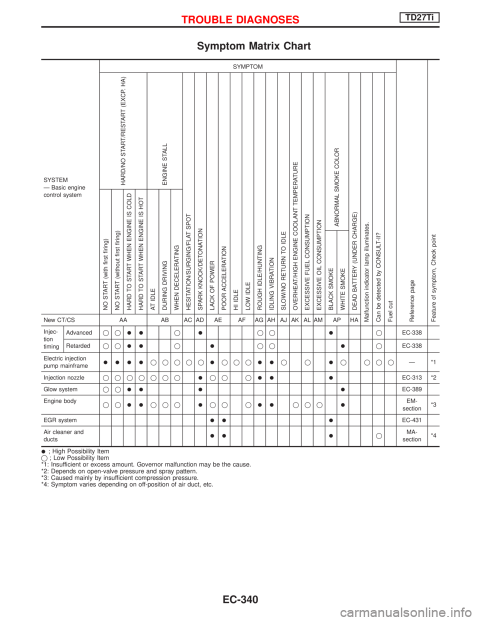
Symptom Matrix Chart
SYSTEM
Ð Basic engine
control systemSYMPTOM
Reference page
Feature of symptom, Check pointHARD/NO START/RESTART (EXCP. HA)
ENGINE STALL
HESITATION/SURGING/FLAT SPOT
SPARK KNOCK/DETONATION
LACK OF POWER
POOR ACCELERATION
HI IDLE
LOW IDLE
ROUGH IDLE/HUNTING
IDLING VIBRATION
SLOW/NO RETURN TO IDLE
OVERHEAT/HIGH ENGINE COOLANT TEMPERATURE
EXCESSIVE FUEL CONSUMPTION
EXCESSIVE OIL CONSUMPTION
ABNORMAL SMOKE COLOR
DEAD BATTERY (UNDER CHARGE)
Malfunction indicator lamp illuminates.
Can be detected by CONSULT-II?
Fuel cutNO START (with first firing)
NO START (without first firing)
HARD TO START WHEN ENGINE IS COLD
HARD TO START WHEN ENGINE IS HOT
AT IDLE
DURING DRIVING
WHEN DECELERATING
BLACK SMOKE
WHITE SMOKENew CT/CS AA AB AC AD AE AF AG AH AJ AK AL AM AP HA
Injec-
tion
timingAdvancedqq
IIqIqqIqEC-338
Retardedqq
IIqIqqIqEC-338
Electric injection
pump mainframe
IIIIqqqqqIqqqIIqqIq qqqÐ*1
Injection nozzleqqqqqqq
Iqq qII IEC-313 *2
Glow systemqq
II I IEC-389
Engine body
qq
IIqqqIqq qIIqqqIEM-
section*3
EGR system
II IEC-431
Air cleaner and
ducts
II IqMA-
section*4
I; High Possibility Item
q; Low Possibility Item
*1: Insufficient or excess amount. Governor malfunction may be the cause.
*2: Depends on open-valve pressure and spray pattern.
*3: Caused mainly by insufficient compression pressure.
*4: Symptom varies depending on off-position of air duct, etc.
TROUBLE DIAGNOSESTD27Ti
EC-340
Page 703 of 1767
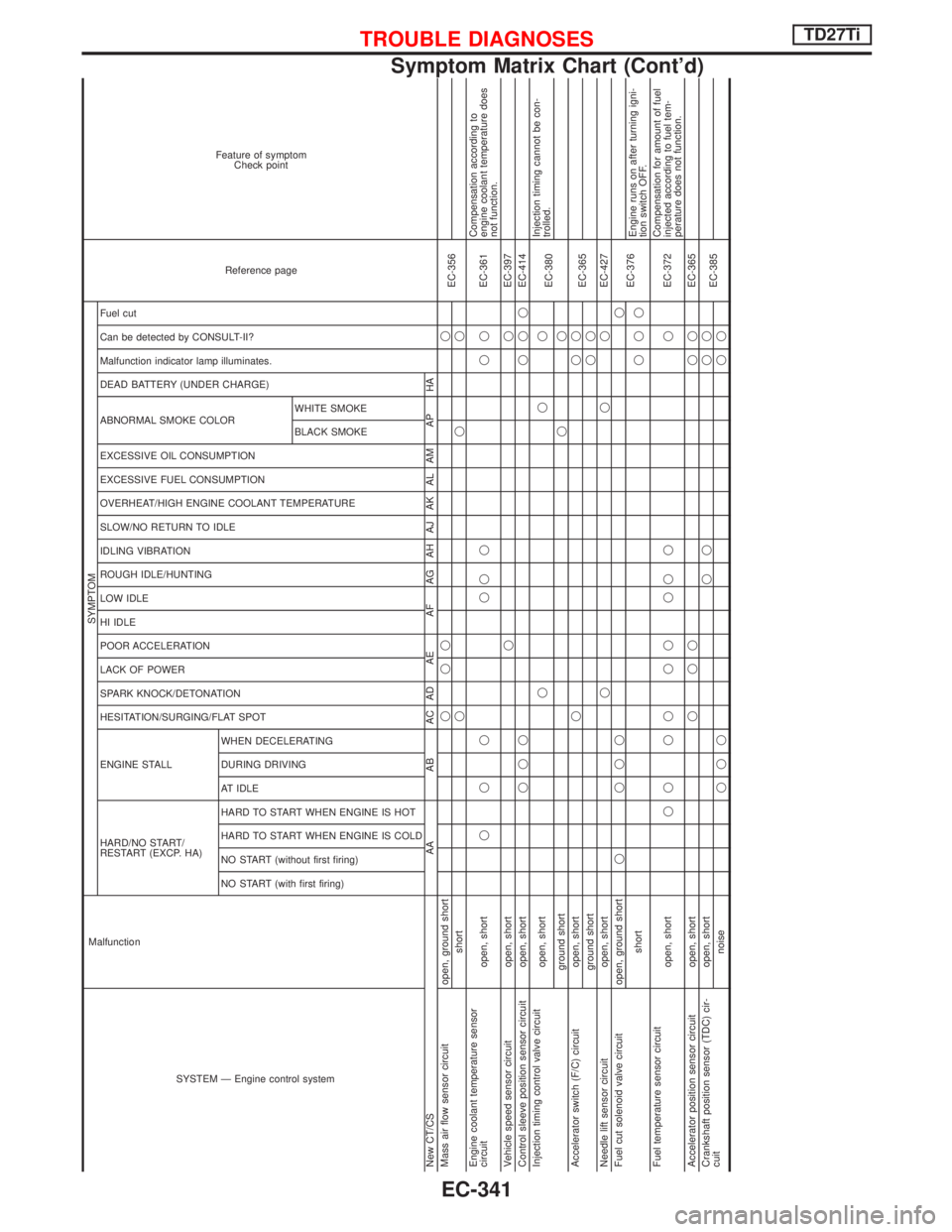
SYSTEM Ð Engine control system Malfunction
SYMPTOM
Reference page Feature of symptom
Check point
HARD/NO START/
RESTART (EXCP. HA) ENGINE STALL HESITATION/SURGING/FLAT SPOT SPARK KNOCK/DETONATION
LACK OF POWER
POOR ACCELERATION
HI IDLE
LOW IDLE
ROUGH IDLE/HUNTING
IDLING VIBRATION
SLOW/NO RETURN TO IDLE
OVERHEAT/HIGH ENGINE COOLANT TEMPERATURE
EXCESSIVE FUEL CONSUMPTION
EXCESSIVE OIL CONSUMPTION ABNORMAL SMOKE COLOR
DEAD BATTERY (UNDER CHARGE) Malfunction indicator lamp illuminates.
Can be detected by CONSULT-II?
Fuel cut
NO START (with first firing) NO START (without first firing)
HARD TO START WHEN ENGINE IS COLD
HARD TO START WHEN ENGINE IS HOT
AT IDLE
DURING DRIVING
WHEN DECELERATINGBLACK SMOKE WHITE SMOKE
New CT/CS AA AB AC AD AE AF AG AH AJ AK AL AM AP HA
Mass air flow sensor circuit open, ground shortqqq q
EC-356
shortqqq
Engine coolant temperature sensor
circuit open, shortqqq qqq qqEC-361Compensation according to
engine coolant temperature does
not function.
Vehicle speed sensor circuit open, shortqqEC-397
Control sleeve position sensor circuit open, shortqqqqqqEC-414
Injection timing control valve circuit
open, shortqqq
EC-380Injection timing cannot be con-
trolled.
ground shortqq
Accelerator switch (F/C) circuit open, shortqqq
EC-365
ground shortqq
Needle lift sensor circuit open, shortqqqEC-427
Fuel cut solenoid valve circuit open, ground shortq qqqq
EC-376
shortqqqEngine runs on after turning igni-
tion switch OFF.
Fuel temperature sensor circuit
open, shortqq qq qq qq q qEC-372Compensation for amount of fuel
injected according to fuel tem-
perature does not function.
Accelerator position sensor circuit open, shortqqq qqEC-365
Crankshaft position sensor (TDC) cir-
cuitopen, shortqq qq
EC-385
noiseqqqqq
TROUBLE DIAGNOSESTD27Ti
Symptom Matrix Chart (Cont'd)
EC-341
Page 704 of 1767
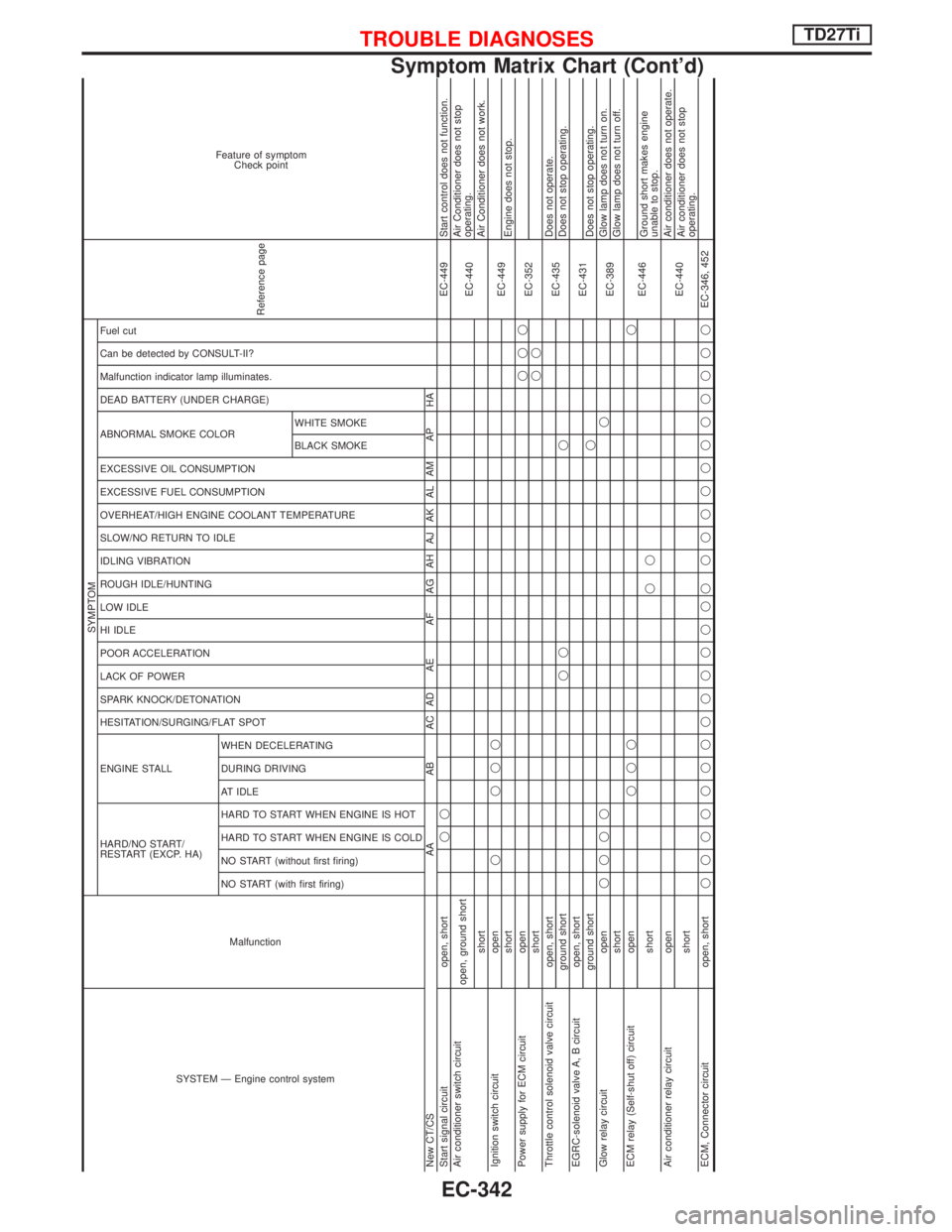
SYSTEM Ð Engine control systemMalfunction
SYMPTOM
Reference page
Feature of symptom
Check point
HARD/NO START/
RESTART (EXCP. HA) ENGINE STALL HESITATION/SURGING/FLAT SPOT SPARK KNOCK/DETONATION
LACK OF POWER
POOR ACCELERATION
HI IDLE
LOW IDLE
ROUGH IDLE/HUNTING
IDLING VIBRATION
SLOW/NO RETURN TO IDLE
OVERHEAT/HIGH ENGINE COOLANT TEMPERATURE
EXCESSIVE FUEL CONSUMPTION
EXCESSIVE OIL CONSUMPTION ABNORMAL SMOKE COLOR
DEAD BATTERY (UNDER CHARGE) Malfunction indicator lamp illuminates.
Can be detected by CONSULT-II?
Fuel cut
NO START (with first firing) NO START (without first firing)
HARD TO START WHEN ENGINE IS COLD
HARD TO START WHEN ENGINE IS HOT
AT IDLE
DURING DRIVING
WHEN DECELERATINGBLACK SMOKE WHITE SMOKE
New CT/CS AA AB AC AD AE AF AG AH AJ AK AL AM AP HA
Start signal circuit open, shortqqEC-449 Start control does not function.
Air conditioner switch circuit
open, ground short
EC-440Air Conditioner does not stop
operating.
shortAir Conditioner does not work.
Ignition switch circuit openq qqq
EC-449
shortEngine does not stop.
Power supply for ECM circuit openqqq
EC-352
shortqq
Throttle control solenoid valve circuit open, short
EC-435Does not operate.
ground shortqq qDoes not stop operating.
EGRC-solenoid valve A, B circuit open, short
EC-431
ground shortqDoes not stop operating.
Glow relay circuit openqqqqq
EC-389Glow lamp does not turn on.
shortGlow lamp does not turn off.
ECM relay (Self-shut off) circuit openqqqq
EC-446
shortqqGround short makes engine
unable to stop.
Air conditioner relay circuit open
EC-440Air conditioner does not operate.
shortAir conditioner does not stop
operating.
ECM, Connector circuit open, shortqqqqqqqqqqqqqq qqqqqqqqqqqEC-346, 452
TROUBLE DIAGNOSESTD27Ti
Symptom Matrix Chart (Cont'd)
EC-342
Page 705 of 1767
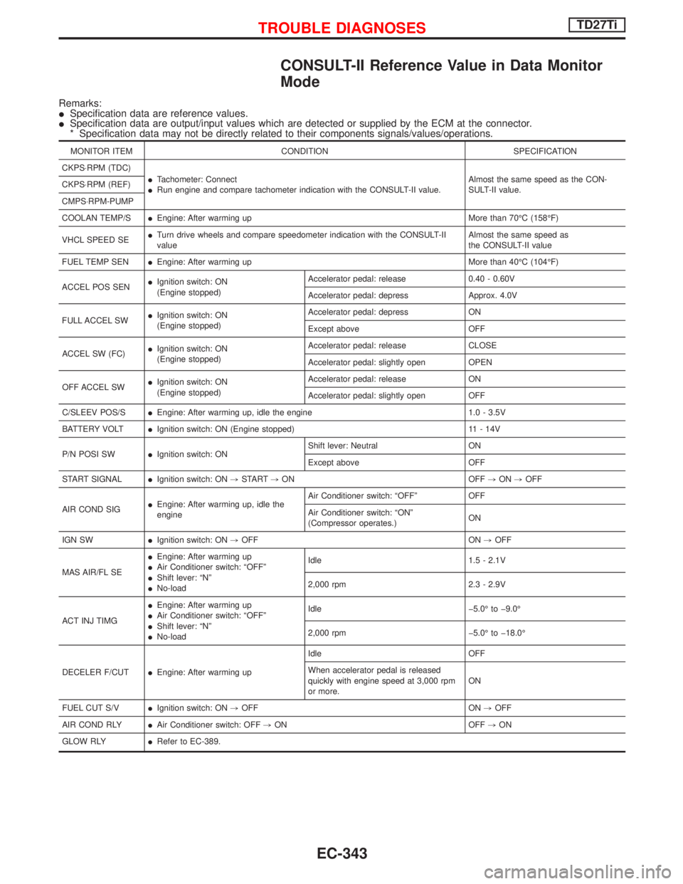
CONSULT-II Reference Value in Data Monitor
Mode
Remarks:
ISpecification data are reference values.
ISpecification data are output/input values which are detected or supplied by the ECM at the connector.
* Specification data may not be directly related to their components signals/values/operations.
MONITOR ITEM CONDITION SPECIFICATION
CKPS×RPM (TDC)
ITachometer: Connect
IRun engine and compare tachometer indication with the CONSULT-II value.Almost the same speed as the CON-
SULT-II value. CKPS×RPM (REF)
CMPS×RPM-PUMP
COOLAN TEMP/SIEngine: After warming up More than 70ÉC (158ÉF)
VHCL SPEED SEITurn drive wheels and compare speedometer indication with the CONSULT-II
valueAlmost the same speed as
the CONSULT-II value
FUEL TEMP SENIEngine: After warming up More than 40ÉC (104ÉF)
ACCEL POS SENIIgnition switch: ON
(Engine stopped)Accelerator pedal: release 0.40 - 0.60V
Accelerator pedal: depress Approx. 4.0V
FULL ACCEL SWIIgnition switch: ON
(Engine stopped)Accelerator pedal: depress ON
Except above OFF
ACCEL SW (FC)IIgnition switch: ON
(Engine stopped)Accelerator pedal: release CLOSE
Accelerator pedal: slightly open OPEN
OFF ACCEL SWIIgnition switch: ON
(Engine stopped)Accelerator pedal: release ON
Accelerator pedal: slightly open OFF
C/SLEEV POS/SIEngine: After warming up, idle the engine 1.0 - 3.5V
BATTERY VOLTIIgnition switch: ON (Engine stopped) 11 - 14V
P/N POSI SWIIgnition switch: ONShift lever: Neutral ON
Except above OFF
START SIGNALIIgnition switch: ON,START,ON OFF,ON,OFF
AIR COND SIGIEngine: After warming up, idle the
engineAir Conditioner switch: ªOFFº OFF
Air Conditioner switch: ªONº
(Compressor operates.)ON
IGN SWIIgnition switch: ON,OFF ON,OFF
MAS AIR/FL SEIEngine: After warming up
IAir Conditioner switch: ªOFFº
IShift lever: ªNº
INo-loadIdle 1.5 - 2.1V
2,000 rpm 2.3 - 2.9V
ACT INJ TIMGIEngine: After warming up
IAir Conditioner switch: ªOFFº
IShift lever: ªNº
INo-loadIdle þ5.0É to þ9.0É
2,000 rpm þ5.0É to þ18.0É
DECELER F/CUTIEngine: After warming upIdle OFF
When accelerator pedal is released
quickly with engine speed at 3,000 rpm
or more.ON
FUEL CUT S/VIIgnition switch: ON,OFF ON,OFF
AIR COND RLYIAir Conditioner switch: OFF,ON OFF,ON
GLOW RLYIRefer to EC-389.
TROUBLE DIAGNOSESTD27Ti
EC-343
Page 706 of 1767
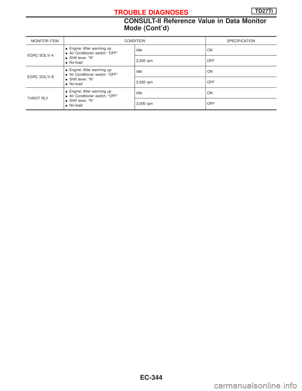
MONITOR ITEM CONDITION SPECIFICATION
EGRC SOL/V AIEngine: After warming up
IAir Conditioner switch: ªOFFº
IShift lever: ªNº
INo-loadIdle ON
3,200 rpm OFF
EGRC SOL/V BIEngine: After warming up
IAir Conditioner switch: ªOFFº
IShift lever: ªNº
INo-loadIdle ON
3,000 rpm OFF
THROT RLYIEngine: After warming up
IAir Conditioner switch: ªOFFº
IShift lever: ªNº
INo-loadIdle ON
3,000 rpm OFF
TROUBLE DIAGNOSESTD27Ti
CONSULT-II Reference Value in Data Monitor
Mode (Cont'd)
EC-344
Page 707 of 1767

Major Sensor Reference Graph in Data Monitor
Mode
The following are the major sensor reference graphs in ªDATA MONITORº mode.
(Select ªHI SPEEDº in ªDATA MONITORº with CONSULT-II.)
ACCEL POS SEN, C/SLEEV POS/S, ACT INJ TIMG
Below is the data for ªACCEL POS SENº, ªC/SLEEV POS/Sº and ªACT INJ TIMGº when revving engine quickly
up to 3,000 rpm under no load after warming up engine sufficiently.
Each value is for reference, the exact value may vary.
NEF766
TROUBLE DIAGNOSESTD27Ti
EC-345
Page 708 of 1767

ECM Terminals and Reference Value
PREPARATION
Perform all voltage measurements with all the connectors con-
nected. Measure ECM terminal voltage at the nearest connector to
the sensors or actuators to be measured as accessing ECM termi-
nals from outside is impossible.
IUse extreme care not to touch 2 pins at the same time.
IData is for comparison and may not be exact.
IUse care not to enlarge the opening to keep the seal in good
condition.
Be sure ECM unit is properly grounded before checking.
ECM HARNESS CONNECTOR TERMINAL LAYOUT
SGI841
MEC032E
TROUBLE DIAGNOSESTD27Ti
EC-346
Page 709 of 1767
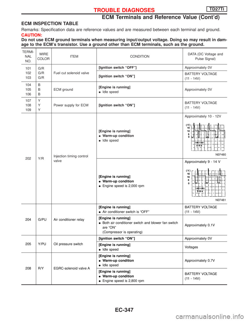
ECM INSPECTION TABLE
Remarks: Specification data are reference values and are measured between each terminal and ground.
CAUTION:
Do not use ECM ground terminals when measuring input/output voltage. Doing so may result in dam-
age to the ECM's transistor. Use a ground other than ECM terminals, such as the ground.
TERMI-
NAL
NO.WIRE
COLORITEM CONDITIONDATA (DC Voltage and
Pulse Signal)
101
102
103G/R
G/R
G/RFuel cut solenoid valve[Ignition switch ªOFFº]Approximately 0V
[Ignition switch ªONº]BATTERY VOLTAGE
(11 - 14V)
104
105
106B
B
BECM ground[Engine is running]
IIdle speedApproximately 0V
107
108
109Y
Y
YPower supply for ECM[Ignition switch ªONº]BATTERY VOLTAGE
(11 - 14V)
202 Y/RInjection timing control
valve[Engine is running]
IWarm-up condition
IIdle speedApproximately 10 - 12V
NEF480
[Engine is running]
IWarm-up condition
IEngine speed is 2,000 rpmApproximately9-14V
NEF481
204 G/PU Air conditioner relay[Engine is running]
IAir conditioner switch is ªOFFºBATTERY VOLTAGE
(11 - 14V)
[Engine is running]
IBoth air conditioner switch and blower fan switch
are ªONº
(Compressor is operating)Approximately 0.1V
205 Y/PU Oil pressure switch[Ignition switch ªONº]Approximately 0V
[Engine is running]
IIdle speedVoltages
208 R/Y EGRC-solenoid valve A[Engine is running]
IWarm-up condition
IIdle speedApproximately 0.7V
[Engine is running]
IWarm-up condition
IEngine speed is 2,800 rpmBATTERY VOLTAGE
(11 - 14V)
TROUBLE DIAGNOSESTD27Ti
ECM Terminals and Reference Value (Cont'd)
EC-347
Page 710 of 1767
![NISSAN TERRANO 2002 Service Repair Manual TERMI-
NAL
NO.WIRE
COLORITEM CONDITIONDATA (DC Voltage and
Pulse Signal)
210 Y/B EGRC-solenoid valve B[Engine is running]
IWarm-up condition
IIdle speedApproximately 0.4V
[Engine is running]
IWarm-up NISSAN TERRANO 2002 Service Repair Manual TERMI-
NAL
NO.WIRE
COLORITEM CONDITIONDATA (DC Voltage and
Pulse Signal)
210 Y/B EGRC-solenoid valve B[Engine is running]
IWarm-up condition
IIdle speedApproximately 0.4V
[Engine is running]
IWarm-up](/img/5/57393/w960_57393-709.png)
TERMI-
NAL
NO.WIRE
COLORITEM CONDITIONDATA (DC Voltage and
Pulse Signal)
210 Y/B EGRC-solenoid valve B[Engine is running]
IWarm-up condition
IIdle speedApproximately 0.4V
[Engine is running]
IWarm-up condition
IEngine speed is 2,500 rpmBATTERY VOLTAGE
(11 - 14V)
213 G/YThrottle control solenoid
valve[Engine is running]
IWarm-up condition
ILow loadApproximately 0V
Except above condition Battery voltage (12 - 14V)
214 LG Glow relay Refer to ªGlow Control Systemº, EC-389.
215 L Malfunction indicator (MI)[Ignition switch ªONº]Approximately 1.0V
[Engine is running]
IIdle speedBATTERY VOLTAGE
(11 - 14V)
218 G/R Sensors' ground[Engine is running]
IWarm-up condition
IIdle speedApproximately 0V
219 LG/R Cooling fan relay[Engine is running]
ICooling fan is not operatingBATTERY VOLTAGE
(11 - 14V)
[Engine is running]
ICooling fan is operatingApproximately 0.1V
221 G/W Glow lamp[Ignition switch ªONº]
IGlow lamp is ªONºApproximately 1V
[Ignition switch ªONº]
IGlow lamp is ªOFFºBATTERY VOLTAGE
(11 - 14V)
223 R/LMass air flow sensor
power supply[Ignition switch ªONº]Approximately 5V
224 L/W Mass air flow sensor[Engine is running]
IWarm-up condition
IIdle speed1.5 - 2.0V
320 WControl sleeve position
sensor[Engine is running]
IIdle speedApproximately 2.6V
NEF477
321 RControl sleeve position
sensor power supply[Engine is running]
IIdle speedApproximately 2.6V
NEF476
TROUBLE DIAGNOSESTD27Ti
ECM Terminals and Reference Value (Cont'd)
EC-348