engine coolant NISSAN TERRANO 2004 Service Manual PDF
[x] Cancel search | Manufacturer: NISSAN, Model Year: 2004, Model line: TERRANO, Model: NISSAN TERRANO 2004Pages: 1833, PDF Size: 53.42 MB
Page 372 of 1833
Diagnostic Procedure
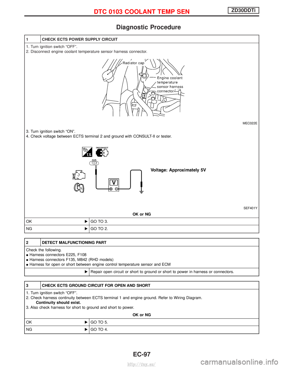
1 CHECK ECTS POWER SUPPLY CIRCUIT
1. Turn ignition switch ªOFFº.
2. Disconnect engine coolant temperature sensor harness connector.
MEC022E
3. Turn ignition switch ªONº.
4. Check voltage between ECTS terminal 2 and ground with CONSULT-II or tester.
SEF401Y
OK or NG
OK EGO TO 3.
NG EGO TO 2.
2 DETECT MALFUNCTIONING PART
Check the following.
IHarness connectors E225, F108
I Harness connectors F135, M842 (RHD models)
I Harness for open or short between engine control temperature sensor and ECM
ERepair open circuit or short to ground or short to power in harness or connectors.
3 CHECK ECTS GROUND CIRCUIT FOR OPEN AND SHORT
1. Turn ignition switch ªOFFº.
2. Check harness continuity between ECTS terminal 1 and engine ground. Refer to Wiring Diagram.
Continuity should exist.
3. Also check harness for short to ground and short to power.
OK or NG
OK EGO TO 5.
NG EGO TO 4.
DTC 0103 COOLANT TEMP SENZD30DDTi
EC-97
http://vnx.su/
Page 373 of 1833
4 DETECT MALFUNCTIONING PART
Check the following.
IHarness connectors E225, F108
I Harness connectors F135, M842 (RHD models)
I Harness for open or short between engine coolant temperature sensor and ECM
ERepair open circuit or short to ground or short to power in harness or connectors.
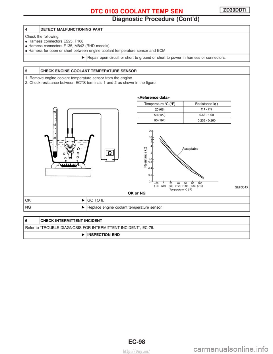
5 CHECK ENGINE COOLANT TEMPERATURE SENSOR
1. Remove engine coolant temperature sensor from the engine.
2. Check resistance between ECTS terminals 1 and 2 as shown in the figure.
SEF304X
OK or NG
OK EGO TO 6.
NG EReplace engine coolant temperature sensor.
6 CHECK INTERMITTENT INCIDENT
Refer to ªTROUBLE DIAGNOSIS FOR INTERMITTENT INCIDENTº, EC-78.
EINSPECTION END
DTC 0103 COOLANT TEMP SENZD30DDTi
Diagnostic Procedure (Cont'd)
EC-98
http://vnx.su/
Page 384 of 1833
Description
SYSTEM DESCRIPTION
SensorInput signal to ECMECM functionActuator
Vehicle speed sensor Vehicle speed
Cooling fan con-
trolCooling fan relay
Engine coolant temperature sensor Engine coolant temperature
Air conditioner switch Air conditioner ªONº signal
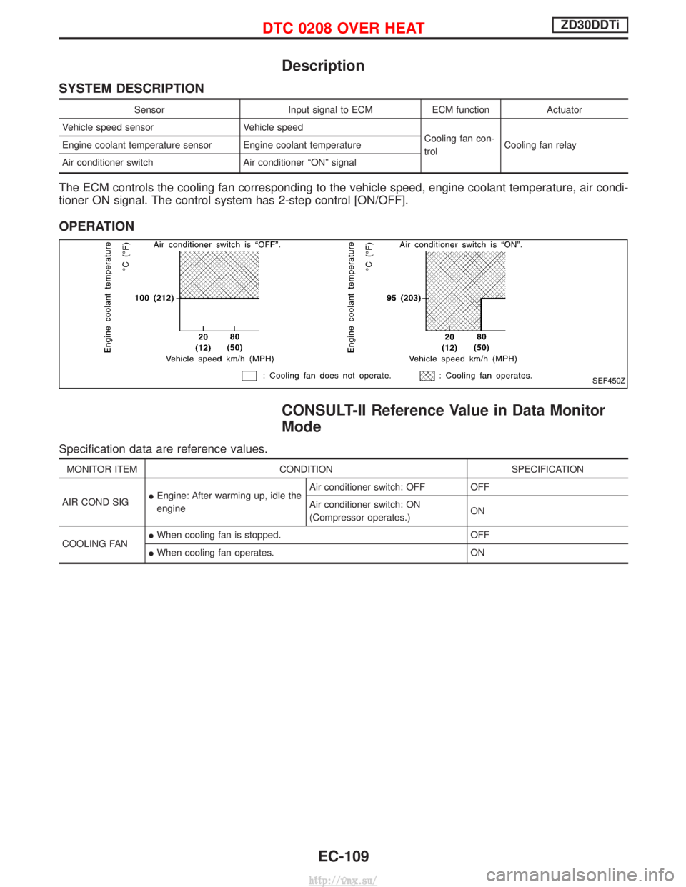
The ECM controls the cooling fan corresponding to the vehicle speed, engine coolant temperature, air condi-
tioner ON signal. The control system has 2-step control [ON/OFF].
OPERATION
CONSULT-II Reference Value in Data Monitor
Mode
Specification data are reference values.
MONITOR ITEM CONDITION SPECIFICATION
AIR COND SIG I
Engine: After warming up, idle the
engine Air conditioner switch: OFF OFF
Air conditioner switch: ON
(Compressor operates.)
ON
COOLING FAN I
When cooling fan is stopped. OFF
I When cooling fan operates. ON
SEF450Z
DTC 0208 OVER HEATZD30DDTi
EC-109
http://vnx.su/
Page 385 of 1833
ECM Terminals and Reference Value
Specification data are reference values and are measured between each terminal and ground.
CAUTION:
Do not use ECM ground terminals when measuring input/output voltage. Doing so may damage the
ECM's transistor. Use a ground other than ECM terminals, such as the ground.
TER-
MINAL NO. WIRE
COLOR ITEM CONDITION DATA (DC Voltage)
14 LG/R Cooling fan relay Engine is running.
Cooling fan is not operating
BATTERY VOLTAGE
(11 - 14V)
Engine is running.
Cooling fan is operating Approximately 0.1V
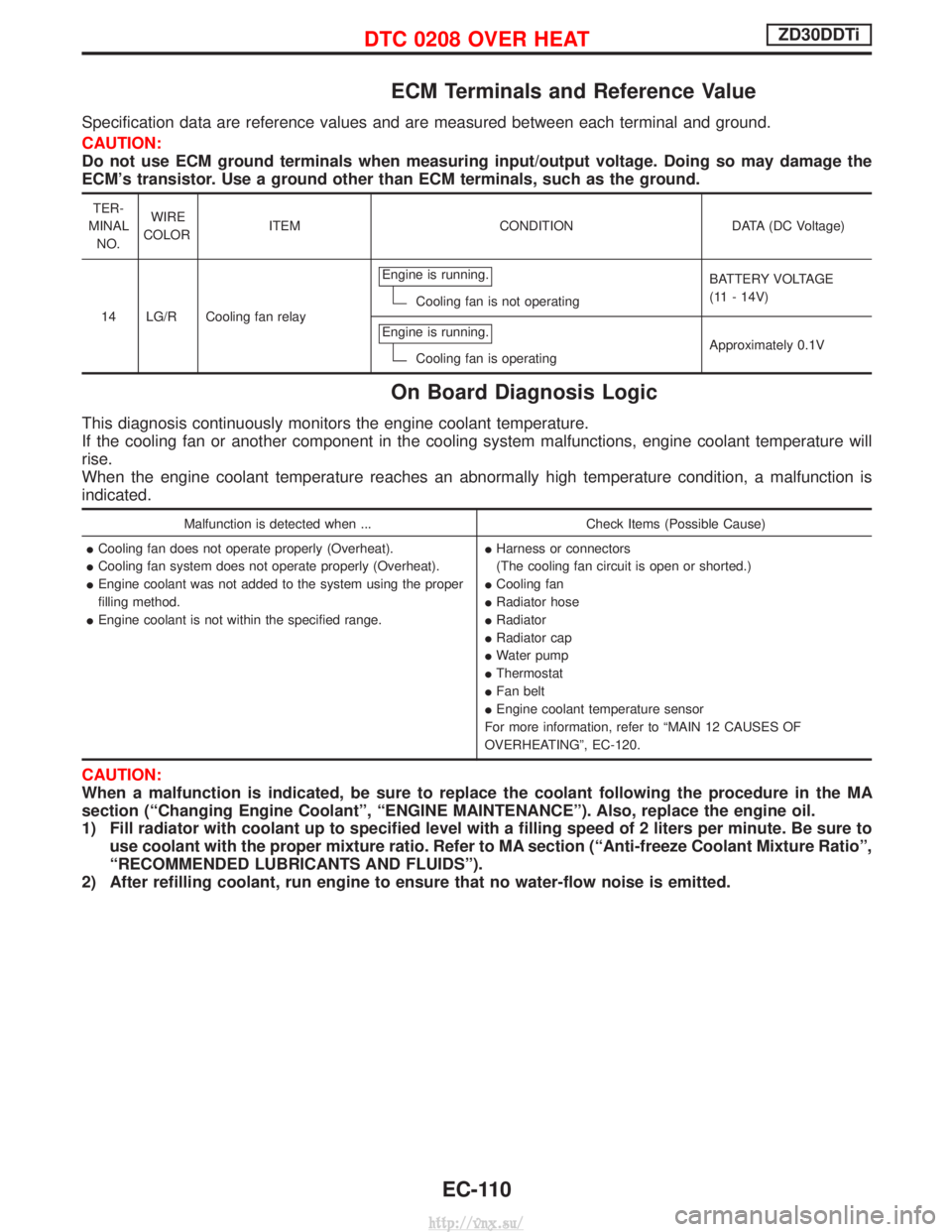
On Board Diagnosis Logic
This diagnosis continuously monitors the engine coolant temperature.
If the cooling fan or another component in the cooling system malfunctions, engine coolant temperature will
rise.
When the engine coolant temperature reaches an abnormally high temperature condition, a malfunction is
indicated.
Malfunction is detected when ...
Check Items (Possible Cause)
I Cooling fan does not operate properly (Overheat).
I Cooling fan system does not operate properly (Overheat).
I Engine coolant was not added to the system using the proper
filling method.
I Engine coolant is not within the specified range. I
Harness or connectors
(The cooling fan circuit is open or shorted.)
I Cooling fan
I Radiator hose
I Radiator
I Radiator cap
I Water pump
I Thermostat
I Fan belt
I Engine coolant temperature sensor
For more information, refer to ªMAIN 12 CAUSES OF
OVERHEATINGº, EC-120.
CAUTION:
When a malfunction is indicated, be sure to replace the coolant following the procedure in the MA
section (ªChanging Engine Coolantº, ªENGINE MAINTENANCEº). Also, replace the engine oil.
1) Fill radiator with coolant up to specified level with a filling speed of 2 liters per minute. Be sure to use coolant with the proper mixture ratio. Refer to MA section (ªAnti-freeze Coolant Mixture Ratioº,
ªRECOMMENDED LUBRICANTS AND FLUIDSº).
2) After refilling coolant, run engine to ensure that no water-flow noise is emitted.
DTC 0208 OVER HEATZD30DDTi
EC-110
http://vnx.su/
Page 386 of 1833
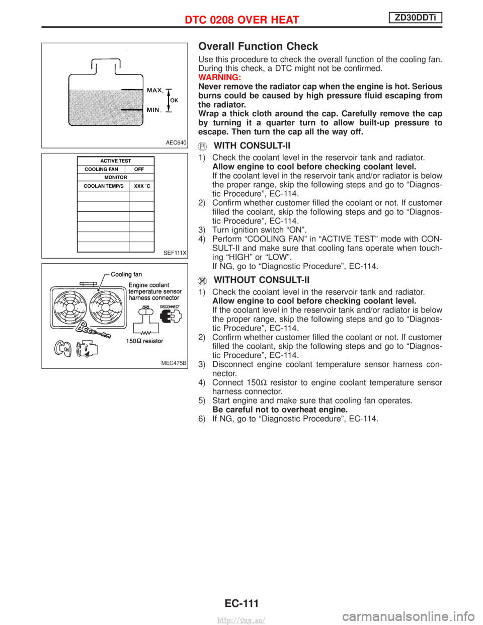
Overall Function Check
Use this procedure to check the overall function of the cooling fan.
During this check, a DTC might not be confirmed.
WARNING:
Never remove the radiator cap when the engine is hot. Serious
burns could be caused by high pressure fluid escaping from
the radiator.
Wrap a thick cloth around the cap. Carefully remove the cap
by turning it a quarter turn to allow built-up pressure to
escape. Then turn the cap all the way off.
WITH CONSULT-II
1) Check the coolant level in the reservoir tank and radiator.Allow engine to cool before checking coolant level.
If the coolant level in the reservoir tank and/or radiator is below
the proper range, skip the following steps and go to ªDiagnos-
tic Procedureº, EC-114.
2) Confirm whether customer filled the coolant or not. If customer filled the coolant, skip the following steps and go to ªDiagnos-
tic Procedureº, EC-114.
3) Turn ignition switch ªONº.
4) Perform ªCOOLING FANº in ªACTIVE TESTº mode with CON- SULT-II and make sure that cooling fans operate when touch-
ing ªHIGHº or ªLOWº.
If NG, go to ªDiagnostic Procedureº, EC-114.
WITHOUT CONSULT-II
1) Check the coolant level in the reservoir tank and radiator.Allow engine to cool before checking coolant level.
If the coolant level in the reservoir tank and/or radiator is below
the proper range, skip the following steps and go to ªDiagnos-
tic Procedureº, EC-114.
2) Confirm whether customer filled the coolant or not. If customer filled the coolant, skip the following steps and go to ªDiagnos-
tic Procedureº, EC-114.
3) Disconnect engine coolant temperature sensor harness con- nector.
4) Connect 150W resistor to engine coolant temperature sensor
harness connector.
5) Start engine and make sure that cooling fan operates. Be careful not to overheat engine.
6) If NG, go to ªDiagnostic Procedureº, EC-114.
AEC640
SEF111X
MEC475B
DTC 0208 OVER HEATZD30DDTi
EC-111
http://vnx.su/
Page 389 of 1833
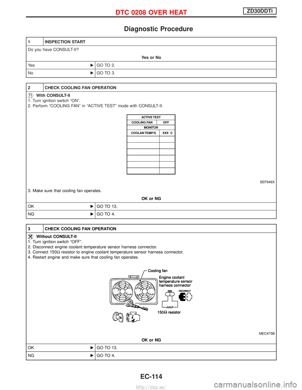
Diagnostic Procedure
1 INSPECTION START
Do you have CONSULT-II?YesorNo
Ye s EGO TO 2.
No EGO TO 3.
2 CHECK COOLING FAN OPERATION
With CONSULT-II
1. Turn ignition switch ªONº.
2. Perform ªCOOLING FANº in ªACTIVE TESTº mode with CONSULT-II.
SEF646X
3. Make sure that cooling fan operates.
OK or NG
OK EGO TO 13.
NG EGO TO 4.
3 CHECK COOLING FAN OPERATION
Without CONSULT-II
1. Turn ignition switch ªOFFº.
2. Disconnect engine coolant temperature sensor harness connector.
3. Connect 150W resistor to engine coolant temperature sensor harness connector.
4. Restart engine and make sure that cooling fan operates.
MEC475B
OK or NG
OK EGO TO 13.
NG EGO TO 4.
DTC 0208 OVER HEATZD30DDTi
EC-114
http://vnx.su/
Page 394 of 1833
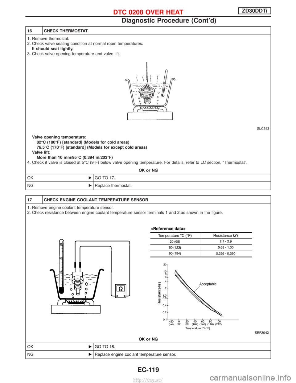
16 CHECK THERMOSTAT
1. Remove thermostat.
2. Check valve seating condition at normal room temperatures.It should seat tightly.
3. Check valve opening temperature and valve lift.
SLC343
Valve opening temperature: 82ÉC (180ÉF) [standard] (Models for cold areas)
76.5ÉC (170ÉF) [standard] (Models for except cold areas)
Valve lift: More than 10 mm/95ÉC (0.394 in/203ÉF)
4. Check if valve is closed at 5ÉC (9ÉF) below valve opening temperature. For details, refer to LC section, ªThermostatº.
OK or NG
OK EGO TO 17.
NG EReplace thermostat.
17 CHECK ENGINE COOLANT TEMPERATURE SENSOR
1. Remove engine coolant temperature sensor.
2. Check resistance between engine coolant temperature sensor terminals 1 and 2 as shown in the figure.
SEF304X
OK or NG
OK EGO TO 18.
NG EReplace engine coolant temperature sensor.
DTC 0208 OVER HEATZD30DDTi
Diagnostic Procedure (Cont'd)
EC-119
http://vnx.su/
Page 395 of 1833
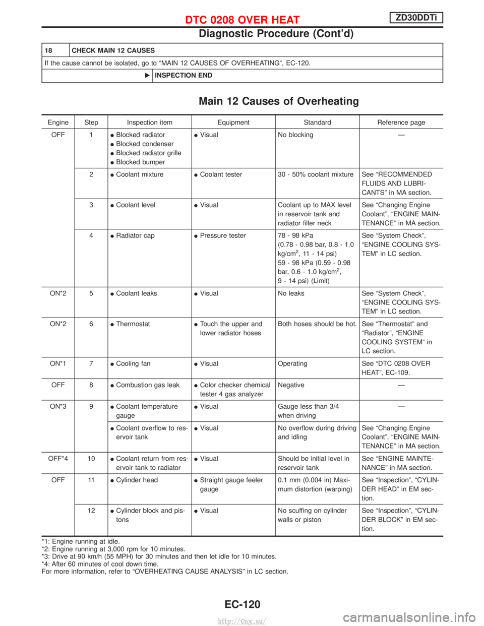
18 CHECK MAIN 12 CAUSES
If the cause cannot be isolated, go to ªMAIN 12 CAUSES OF OVERHEATINGº, EC-120.EINSPECTION END
Main 12 Causes of Overheating
Engine Step Inspection item EquipmentStandardReference page
OFF 1 IBlocked radiator
I Blocked condenser
I Blocked radiator grille
I Blocked bumper I
Visual No blocking Ð
2 ICoolant mixture ICoolant tester 30 - 50% coolant mixture See ªRECOMMENDED
FLUIDS AND LUBRI-
CANTSº in MA section.
3 ICoolant level IVisual Coolant up to MAX level
in reservoir tank and
radiator filler neck See ªChanging Engine
Coolantº, ªENGINE MAIN-
TENANCEº in MA section.
4 IRadiator cap IPressure tester 78 - 98 kPa
(0.78 - 0.98 bar, 0.8 - 1.0
kg/cm
2, 11 - 14 psi)
59 - 98 kPa (0.59 - 0.98
bar, 0.6 - 1.0 kg/cm
2,
9 - 14 psi) (Limit) See ªSystem Checkº,
ªENGINE COOLING SYS-
TEMº in LC section.
ON*2 5 ICoolant leaks IVisual No leaks See ªSystem Checkº,
ªENGINE COOLING SYS-
TEMº in LC section.
ON*2 6 IThermostat ITouch the upper and
lower radiator hoses Both hoses should be hot. See ªThermostatº and
ªRadiatorº, ªENGINE
COOLING SYSTEMº in
LC section.
ON*1 7 ICooling fan IVisual Operating See ªDTC 0208 OVER
HEATº, EC-109.
OFF 8 ICombustion gas leak IColor checker chemical
tester 4 gas analyzer Negative Ð
ON*3 9 ICoolant temperature
gauge I
Visual Gauge less than 3/4
when driving Ð
I Coolant overflow to res-
ervoir tank I
Visual No overflow during driving
and idling See ªChanging Engine
Coolantº, ªENGINE MAIN-
TENANCEº in MA section.
OFF*4 10 ICoolant return from res-
ervoir tank to radiator I
Visual Should be initial level in
reservoir tank See ªENGINE MAINTE-
NANCEº in MA section.
OFF 11 ICylinder head IStraight gauge feeler
gauge 0.1 mm (0.004 in) Maxi-
mum distortion (warping) See ªInspectionº, ªCYLIN-
DER HEADº in EM sec-
tion.
12 ICylinder block and pis-
tons I
Visual No scuffing on cylinder
walls or piston See ªInspectionº, ªCYLIN-
DER BLOCKº in EM sec-
tion.
*1: Engine running at idle.
*2: Engine running at 3,000 rpm for 10 minutes.
*3: Drive at 90 km/h (55 MPH) for 30 minutes and then let idle for 10 minutes.
*4: After 60 minutes of cool down time.
For more information, refer to ªOVERHEATING CAUSE ANALYSISº in LC section.
DTC 0208 OVER HEATZD30DDTi
Diagnostic Procedure (Cont'd)
EC-120
http://vnx.su/
Page 502 of 1833
Description
SYSTEM DESCRIPTION
SensorInput Signal to ECMECM FunctionActuator
Electronic controlled fuel injection pump Fuel injection signal
EGR volume
controlEGR volume control valve
Crankshaft position sensor (TDC) Engine speed
Vehicle speed sensor
Vehicle speed
Engine coolant temperature sensor Engine coolant temperature
Ignition switch Start signal
Throttle position sensor Throttle position
Battery Battery voltage
Mass air flow sensor Amount of intake air
Air conditioner switch Air conditioner operation
Electrical load Electrical load signal
PNP switch Park/Neutral position signal
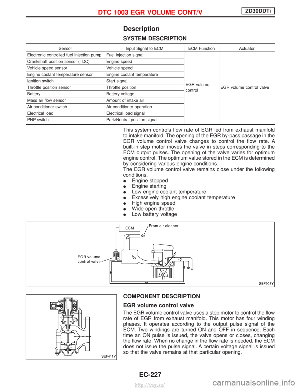
This system controls flow rate of EGR led from exhaust manifold
to intake manifold. The opening of the EGR by-pass passage in the
EGR volume control valve changes to control the flow rate. A
built-in step motor moves the valve in steps corresponding to the
ECM output pulses. The opening of the valve varies for optimum
engine control. The optimum value stored in the ECM is determined
by considering various engine conditions.
The EGR volume control valve remains close under the following
conditions.
IEngine stopped
I Engine starting
I Low engine coolant temperature
I Excessively high engine coolant temperature
I High engine speed
I Wide open throttle
I Low battery voltage
COMPONENT DESCRIPTION
EGR volume control valve
The EGR volume control valve uses a step motor to control the flow
rate of EGR from exhaust manifold. This motor has four winding
phases. It operates according to the output pulse signal of the
ECM. Two windings are turned ON and OFF in sequence. Each
time an ON pulse is issued, the valve opens or closes, changing
the flow rate. When no change in the flow rate is needed, the ECM
does not issue the pulse signal. A certain voltage signal is issued
so that the valve remains at that particular opening.
SEF908Y
SEF411Y
DTC 1003 EGR VOLUME CONT/VZD30DDTi
EC-227
http://vnx.su/
Page 519 of 1833
Description
SYSTEM DESCRIPTION
Sensor Input Signal to ECMECM
Function Actuator
Crankshaft position
sensor (TDC) Engine speed
Glow
control Glow lamp,
Glow relay "
Glow plugs
Engine coolant tem-
perature sensor Engine coolant tem-
perature
When engine coolant temperature is more than approximately 75ÉC
(167ÉF), the glow relay turns off, inactivating the quick-glow control
until coolant temperature drops below approximately 55ÉC (131ÉF).
When coolant temperature is lower than approximately 75ÉC
(167ÉF):
I
Ignition switch ON
After ignition switch has turned to ON, the glow relay turns ON
for a certain period of time in relation to engine coolant
temperature, allowing current to flow through glow plug.
I Cranking
The glow relay turns ON, allowing current to flow through glow
plug.
I Starting
After engine has started, current continues to flow through glow
plug (after-glow mode) for a certain period in relation to engine
coolant temperature.
When engine speed exceeds approximately 4,800 rpm, current
flow through glow plug is interrupted.
The glow indicator lamp turns ON for a certain period of time in
relation to engine coolant temperature at the time glow relay is
turned ON.
COMPONENT DESCRIPTION
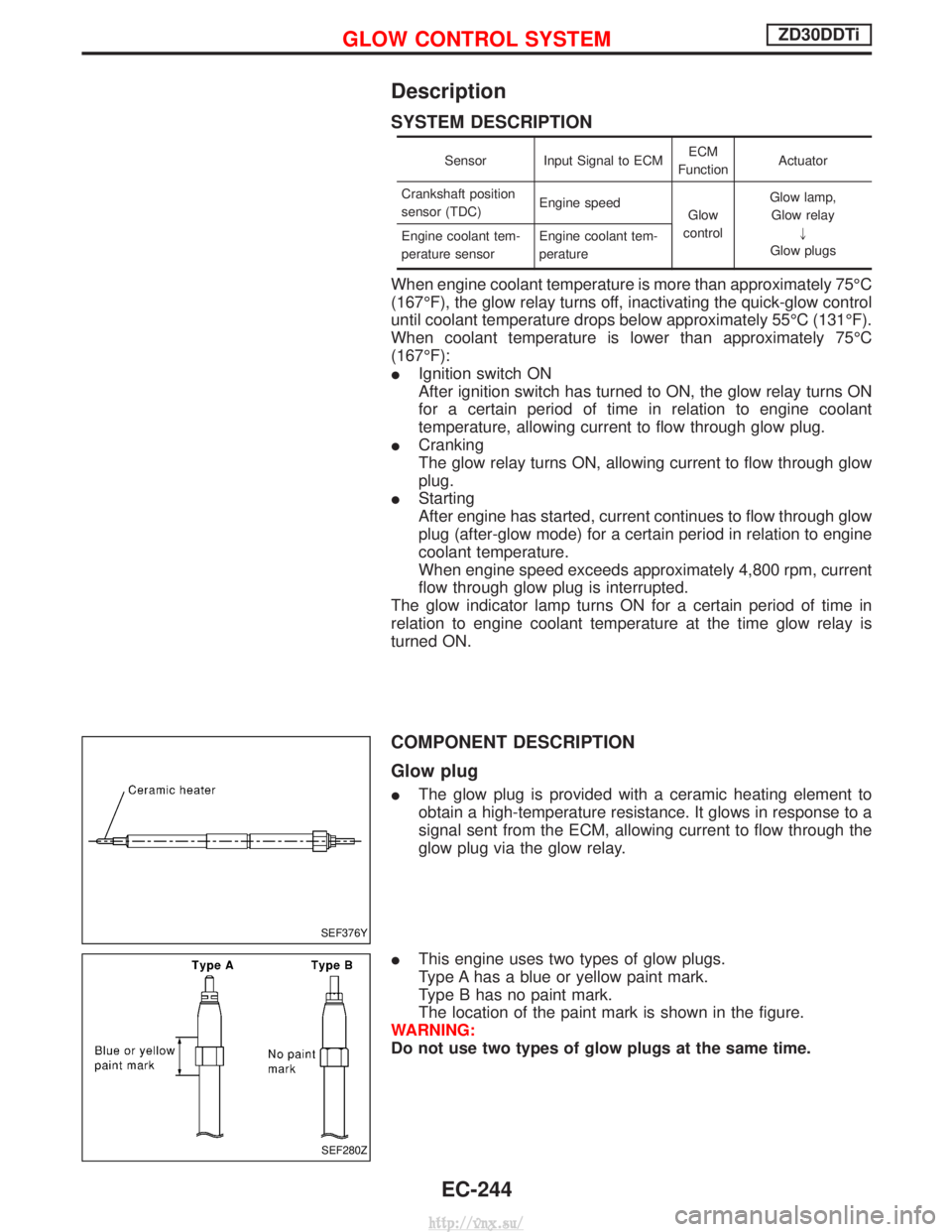
Glow plug
I The glow plug is provided with a ceramic heating element to
obtain a high-temperature resistance. It glows in response to a
signal sent from the ECM, allowing current to flow through the
glow plug via the glow relay.
I This engine uses two types of glow plugs.
Type A has a blue or yellow paint mark.
Type B has no paint mark.
The location of the paint mark is shown in the figure.
WARNING:
Do not use two types of glow plugs at the same time.
SEF376Y
SEF280Z
GLOW CONTROL SYSTEMZD30DDTi
EC-244
http://vnx.su/