engine coolant NISSAN TERRANO 2004 Service Repair Manual
[x] Cancel search | Manufacturer: NISSAN, Model Year: 2004, Model line: TERRANO, Model: NISSAN TERRANO 2004Pages: 1833, PDF Size: 53.42 MB
Page 1153 of 1833
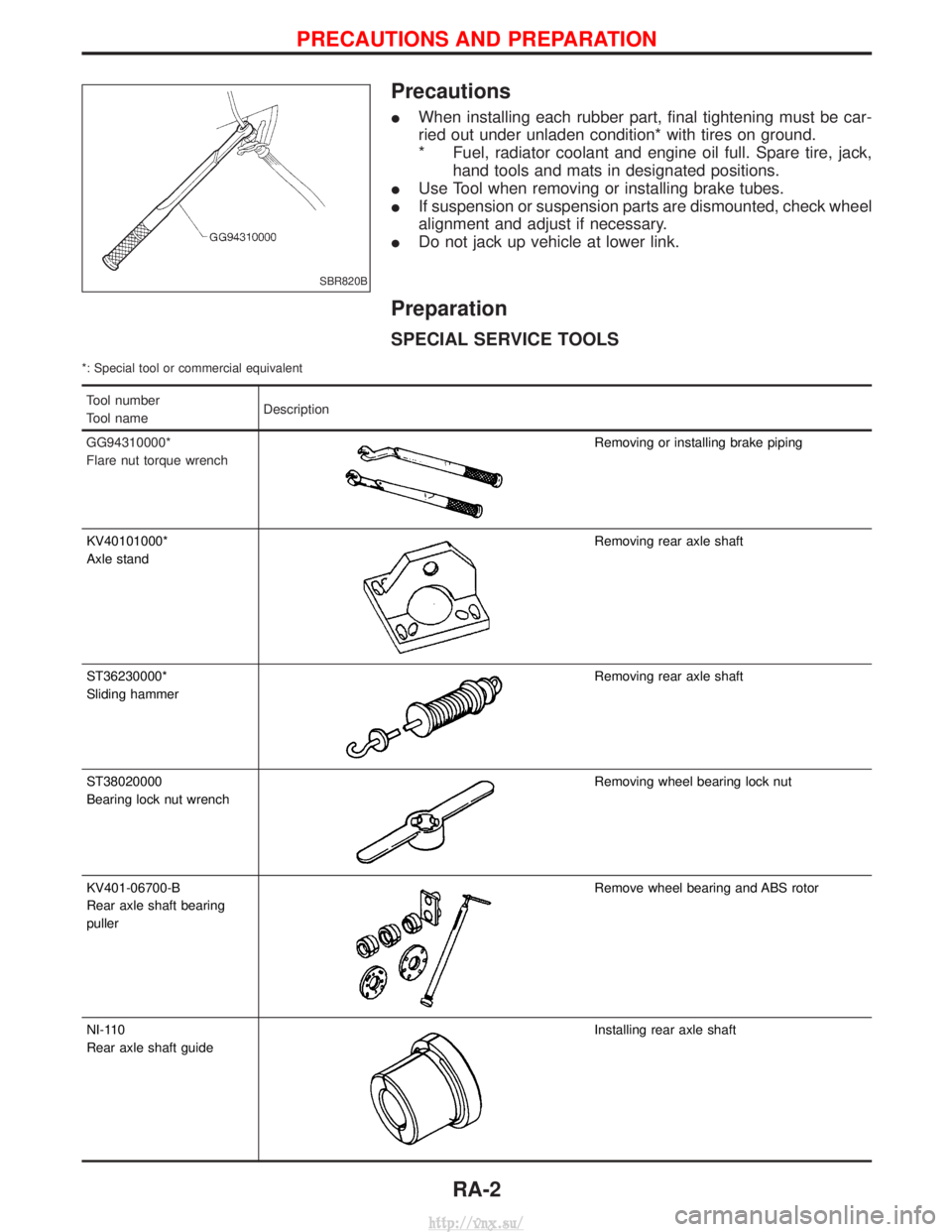
Precautions
IWhen installing each rubber part, final tightening must be car-
ried out under unladen condition* with tires on ground.
* Fuel, radiator coolant and engine oil full. Spare tire, jack,
hand tools and mats in designated positions.
I Use Tool when removing or installing brake tubes.
I If suspension or suspension parts are dismounted, check wheel
alignment and adjust if necessary.
I Do not jack up vehicle at lower link.
Preparation
SPECIAL SERVICE TOOLS
*: Special tool or commercial equivalent
Tool number
Tool name Description
GG94310000*
Flare nut torque wrench
Removing or installing brake piping
KV40101000*
Axle stand
Removing rear axle shaft
ST36230000*
Sliding hammer
Removing rear axle shaft
ST38020000
Bearing lock nut wrench
Removing wheel bearing lock nut
KV401-06700-B
Rear axle shaft bearing
puller
Remove wheel bearing and ABS rotor
NI-110
Rear axle shaft guide
Installing rear axle shaft
SBR820B
PRECAUTIONS AND PREPARATION
RA-2
http://vnx.su/
Page 1180 of 1833
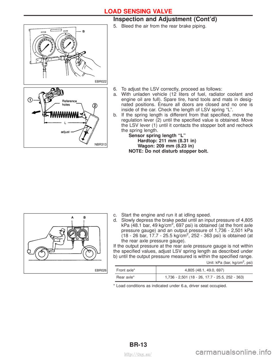
5. Bleed the air from the rear brake piping.
6. To adjust the LSV correctly, proceed as follows:
a. With unladen vehicle (12 liters of fuel, radiator coolant andengine oil are full). Spare tire, hand tools and mats in desig-
nated positions. Ensure all doors are closed and no one is
inside of the car. Check the length of LSV spring ªLº.
b. If the spring length is different from that specified, move the regulation lever (2) until the specified value is obtained. Move
the LSV lever (1) until it contacts the stopper bolt and recheck
the spring length.Sensor spring length ªLº Hardtop: 211 mm (8.31 in)
Wagon: 209 mm (8.23 in)
NOTE: Do not disturb stopper bolt.
c. Start the engine and run it at idling speed.
d. Slowly depress the brake pedal until an input pressure of 4,805 kPa (48.1 bar, 49 kg/cm
2, 697 psi) is obtained (at the front axle
pressure gauge) and an output pressure of 1,736 - 2,501 kPa
(18 - 26 bar, 17.7 - 25.5 kg/cm
2, 252 - 363 psi) is obtained (at
the rear axle pressure gauge).
If the output pressure at the rear axle pressure gauge is not within
the specified values, adjust LSV spring length as described under
b) until the output pressure measured is within the specified range.
Unit: kPa (bar, kg/cm2, psi)
Front axle* 4,805 (48.1, 49.0, 697)
Rear axle* 1,736 - 2,501 (18 - 26, 17.7 - 25.5, 252 - 363)
* Load conditions as indicated under 6.a, driver seat occupied.
EBR022
NBR313
EBR026
LOAD SENSING VALVE
Inspection and Adjustment (Cont'd)
BR-13
http://vnx.su/
Page 1540 of 1833
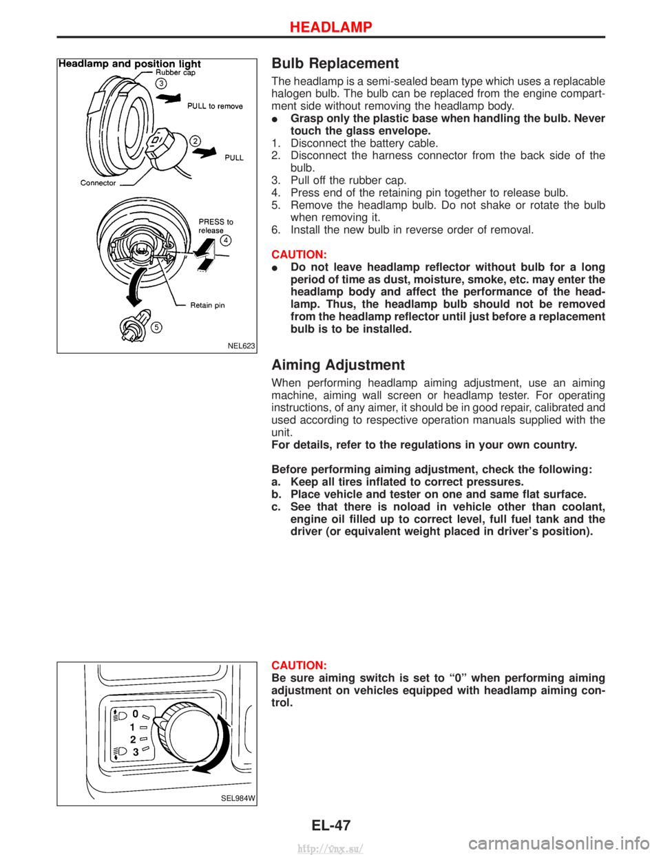
Bulb Replacement
The headlamp is a semi-sealed beam type which uses a replacable
halogen bulb. The bulb can be replaced from the engine compart-
ment side without removing the headlamp body.
IGrasp only the plastic base when handling the bulb. Never
touch the glass envelope.
1. Disconnect the battery cable.
2. Disconnect the harness connector from the back side of the bulb.
3. Pull off the rubber cap.
4. Press end of the retaining pin together to release bulb.
5. Remove the headlamp bulb. Do not shake or rotate the bulb when removing it.
6. Install the new bulb in reverse order of removal.
CAUTION:
I Do not leave headlamp reflector without bulb for a long
period of time as dust, moisture, smoke, etc. may enter the
headlamp body and affect the performance of the head-
lamp. Thus, the headlamp bulb should not be removed
from the headlamp reflector until just before a replacement
bulb is to be installed.
Aiming Adjustment
When performing headlamp aiming adjustment, use an aiming
machine, aiming wall screen or headlamp tester. For operating
instructions, of any aimer, it should be in good repair, calibrated and
used according to respective operation manuals supplied with the
unit.
For details, refer to the regulations in your own country.
Before performing aiming adjustment, check the following:
a. Keep all tires inflated to correct pressures.
b. Place vehicle and tester on one and same flat surface.
c. See that there is noload in vehicle other than coolant,
engine oil filled up to correct level, full fuel tank and the
driver (or equivalent weight placed in driver's position).
CAUTION:
Be sure aiming switch is set to ª0º when performing aiming
adjustment on vehicles equipped with headlamp aiming con-
trol.
NEL623
SEL984W
HEADLAMP
EL-47
http://vnx.su/
Page 1550 of 1833
Front Fog Lamp Aiming Adjustment
When performing fog lamp aiming adjustment, use an aiming
machine, aiming wall screen or headlamp tester. The aimer should
be in good operational condition, calibrated and used according to
the relevant operation manuals supplied with the unit.
If an aimer is not available, aiming adjustment can be done as fol-
lows:
For details, refer to the regulations in your own country.
CAUTION:
IKeep all tires inflated to correct pressures.
I Place vehicle and tester on one and the same flat surface.
I Ensure that there is no-load in the vehicle other than
coolant, engine oil (filled up to correct level), full fuel tank
and the driver (or equivalent weight placed in driver's posi-
tion).
For details of front fog lamp aiming adjustment, refer to ªAiming
Adjustmentº, EL-47.
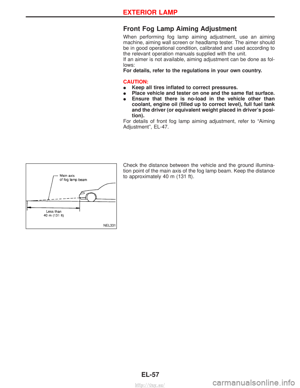
Check the distance between the vehicle and the ground illumina-
tion point of the main axis of the fog lamp beam. Keep the distance
to approximately 40 m (131 ft).
NEL331
EXTERIOR LAMP
EL-57
http://vnx.su/
Page 1576 of 1833
![NISSAN TERRANO 2004 Service Repair Manual POWER SUPPLY AND GROUND CIRCUIT
Power is supplied at all times
Ithrough 10A fuse [No. 16, located in the fuse block (J/B)]
I to combination meter terminal 27.
With the ignition switch in the ON or STA NISSAN TERRANO 2004 Service Repair Manual POWER SUPPLY AND GROUND CIRCUIT
Power is supplied at all times
Ithrough 10A fuse [No. 16, located in the fuse block (J/B)]
I to combination meter terminal 27.
With the ignition switch in the ON or STA](/img/5/57394/w960_57394-1575.png)
POWER SUPPLY AND GROUND CIRCUIT
Power is supplied at all times
Ithrough 10A fuse [No. 16, located in the fuse block (J/B)]
I to combination meter terminal 27.
With the ignition switch in the ON or START position, power is supplied
I through 10A fuse [No. 12, located in the fuse block (J/B)]
I to combination meter terminal 28.
Ground is supplied
I through body grounds F36, F47 (LHD models) or M33, M754 (RHD models)
I to combination meter terminal 29.
WATER TEMPERATURE GAUGE
The water temperature gauge indicates the engine coolant temperature.
Thermal transmitter provides a engine coolant temperature signal to combination meter for water temperature
gauge.
TACHOMETER
The tachometer indicates engine speed in revolution per minutes (rpm). ECM provides an engine speed sig-
nal to combination meter for tachometer.
FUEL GAUGE
The fuel gauge indicates the approximate fuel level in the fuel tank.
The fuel gauge is regulated by a variable ground signal supplied
Ifrom body grounds B10 and B18
I through terminal 3 of the fuel level sensor unit and
I through terminal 2 (TD27Ti engine) or 1 (ZD30DDTi engine) of the fuel level sensor unit
I to combination meter terminal 13 for the fuel gauge.
SPEEDOMETER
The combination meter receives a signal from vehicle speed sensor. The speedometer converts the signal into
the vehicle speed displayed.
AMBIENT TEMPERATURE GAUGE
Ambient temperature sensor provides the signal for ambient temperature to combination meter.
METER AND GAUGES
System Description (Cont'd)
EL-83
http://vnx.su/
Page 1819 of 1833
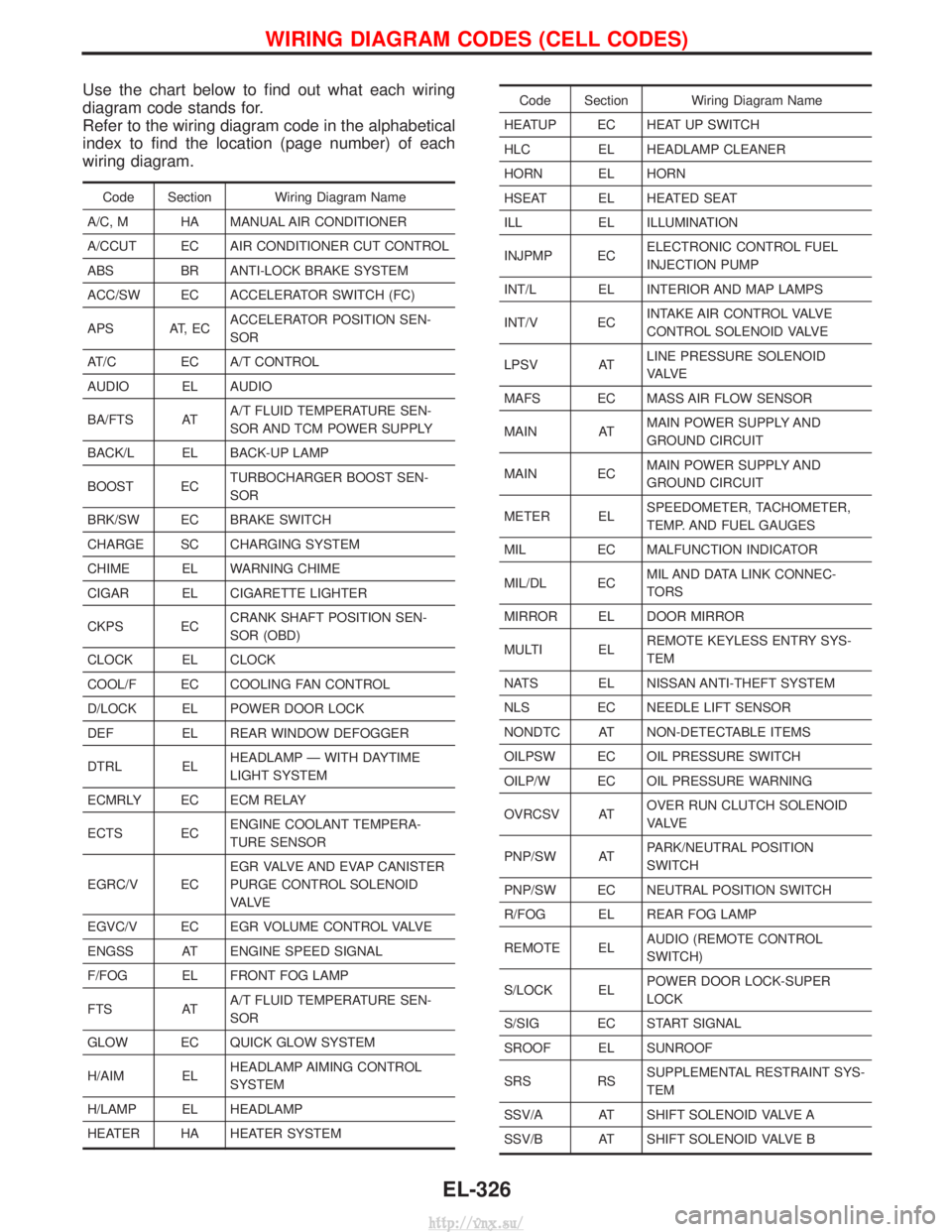
Use the chart below to find out what each wiring
diagram code stands for.
Refer to the wiring diagram code in the alphabetical
index to find the location (page number) of each
wiring diagram.
Code Section Wiring Diagram Name
A/C, M HA MANUAL AIR CONDITIONER
A/CCUT EC AIR CONDITIONER CUT CONTROL
ABS BR ANTI-LOCK BRAKE SYSTEM
ACC/SW EC ACCELERATOR SWITCH (FC)
APS AT, EC ACCELERATOR POSITION SEN-
SOR
AT/C EC A/T CONTROL
AUDIO EL AUDIO
BA/FTS AT A/T FLUID TEMPERATURE SEN-
SOR AND TCM POWER SUPPLY
BACK/L EL BACK-UP LAMP
BOOST EC TURBOCHARGER BOOST SEN-
SOR
BRK/SW EC BRAKE SWITCH
CHARGE SC CHARGING SYSTEM
CHIME EL WARNING CHIME
CIGAR EL CIGARETTE LIGHTER
CKPS EC CRANK SHAFT POSITION SEN-
SOR (OBD)
CLOCK EL CLOCK
COOL/F EC COOLING FAN CONTROL
D/LOCK EL POWER DOOR LOCK
DEF EL REAR WINDOW DEFOGGER
DTRL EL HEADLAMP Ð WITH DAYTIME
LIGHT SYSTEM
ECMRLY EC ECM RELAY
ECTS EC ENGINE COOLANT TEMPERA-
TURE SENSOR
EGRC/V EC EGR VALVE AND EVAP CANISTER
PURGE CONTROL SOLENOID
VA LV E
EGVC/V EC EGR VOLUME CONTROL VALVE
ENGSS AT ENGINE SPEED SIGNAL
F/FOG EL FRONT FOG LAMP
FTS AT A/T FLUID TEMPERATURE SEN-
SOR
GLOW EC QUICK GLOW SYSTEM
H/AIM EL HEADLAMP AIMING CONTROL
SYSTEM
H/LAMP EL HEADLAMP
HEATER HA HEATER SYSTEM
Code Section Wiring Diagram Name
HEATUP EC HEAT UP SWITCH
HLC EL HEADLAMP CLEANER
HORN EL HORN
HSEAT EL HEATED SEAT
ILL EL ILLUMINATION
INJPMP EC ELECTRONIC CONTROL FUEL
INJECTION PUMP
INT/L EL INTERIOR AND MAP LAMPS
INT/V EC INTAKE AIR CONTROL VALVE
CONTROL SOLENOID VALVE
LPSV AT LINE PRESSURE SOLENOID
VA LV E
MAFS EC MASS AIR FLOW SENSOR
MAIN AT MAIN POWER SUPPLY AND
GROUND CIRCUIT
MAIN EC MAIN POWER SUPPLY AND
GROUND CIRCUIT
METER EL SPEEDOMETER, TACHOMETER,
TEMP. AND FUEL GAUGES
MIL EC MALFUNCTION INDICATOR
MIL/DL EC MIL AND DATA LINK CONNEC-
TORS
MIRROR EL DOOR MIRROR
MULTI EL REMOTE KEYLESS ENTRY SYS-
TEM
NATS EL NISSAN ANTI-THEFT SYSTEM
NLS EC NEEDLE LIFT SENSOR
NONDTC AT NON-DETECTABLE ITEMS
OILPSW EC OIL PRESSURE SWITCH
OILP/W EC OIL PRESSURE WARNING
OVRCSV AT OVER RUN CLUTCH SOLENOID
VA LV E
PNP/SW AT PARK/NEUTRAL POSITION
SWITCH
PNP/SW EC NEUTRAL POSITION SWITCH
R/FOG EL REAR FOG LAMP
REMOTE EL AUDIO (REMOTE CONTROL
SWITCH)
S/LOCK EL POWER DOOR LOCK-SUPER
LOCK
S/SIG EC START SIGNAL
SROOF EL SUNROOF
SRS RS SUPPLEMENTAL RESTRAINT SYS-
TEM
SSV/A AT SHIFT SOLENOID VALVE A
SSV/B AT SHIFT SOLENOID VALVE B
WIRING DIAGRAM CODES (CELL CODES)
EL-326
http://vnx.su/
Page 1828 of 1833
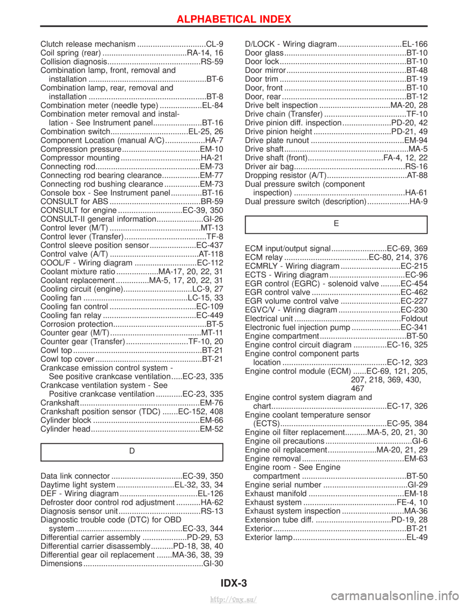
Clutch release mechanism ...............................CL-9
Coil spring (rear) ......................................RA-14, 16
Collision diagnosis..........................................RS-59
Combination lamp, front, removal andinstallation .....................................................BT-6
Combination lamp, rear, removal and installation .....................................................BT-8
Combination meter (needle type) ...................EL-84
Combination meter removal and instal- lation - See Instrument panel......................BT-16
Combination switch...................................EL-25, 26
Component Location (manual A/C) ..................HA-7
Compression pressure ...................................EM-10
Compressor mounting ....................................HA-21
Connecting rod...............................................EM-73
Connecting rod bearing clearance.................EM-77
Connecting rod bushing clearance ................EM-73
Console box - See Instrument panel ..............BT-16
CONSULT for ABS .........................................BR-59
CONSULT for engine .............................EC-39, 350
CONSULT-II general information.....................GI-26
Control lever (M/T) .........................................MT-13
Control lever (Transfer) .....................................TF-8
Control sleeve position sensor .....................EC-437
Control valve (A/T) ........................................AT-118
COOL/F - Wiring diagram ............................EC-112
Coolant mixture ratio ...................MA-17, 20, 22, 31
Coolant replacement ...............MA-5, 17, 20, 22, 31
Cooling circuit (engine)...............................LC-9, 27
Cooling fan ...............................................LC-15, 33
Cooling fan control .......................................EC-109
Cooling fan relay ..........................................EC-449
Corrosion protection..........................................BT-5
Counter gear (M/T) .........................................MT-11
Counter gear (Transfer) ............................TF-10, 20
Cowl top ..........................................................BT-21
Cowl top cover ................................................BT-21
Crankcase emission control system - See positive crankcase ventilation .....EC-23, 335
Crankcase ventilation system - See Positive crankcase ventilation ............EC-23, 335
Crankshaft ......................................................EM-76
Crankshaft position sensor (TDC) .......EC-152, 408
Cylinder block ................................................EM-66
Cylinder head .................................................EM-52
D
Data link connector ................................EC-39, 350
Daytime light system ..........................EL-32, 33, 34
DEF - Wiring diagram ...................................EL-126
Defroster door control rod adjustment ...........HA-62
Diagnosis sensor unit .....................................RS-13
Diagnostic trouble code (DTC) for OBDsystem ................................................EC-33, 344
Differential carrier assembly ....................PD-29, 53
Differential carrier disassembly..........PD-18, 38, 40
Differential gear oil replacement .......MA-36, 38, 39
Dimensions ......................................................GI-30 D/LOCK - Wiring diagram .............................EL-166
Door glass .......................................................BT-10
Door lock .........................................................BT-10
Door mirror ......................................................BT-48
Door trim .........................................................BT-19
Door, front .......................................................BT-10
Door, rear ........................................................BT-12
Drive belt inspection ................................MA-20, 28
Drive chain (Transfer) .....................................TF-10
Drive pinion diff. inspection ......................PD-20, 42
Drive pinion height ...................................PD-21, 49
Drive plate runout ..........................................EM-94
Drive shaft ........................................................MA-5
Drive shaft (front)..................................FA-4, 12, 22
Driver air bag..................................................RS-16
Dropping resistor (A/T)....................................AT-88
Dual pressure switch (component
inspection) ..................................................HA-61
Dual pressure switch (description) ...................HA-9
E
ECM input/output signal .........................EC-69, 369
ECM relay ......................................EC-80, 214, 376
ECMRLY - Wiring diagram ...........................EC-215
ECTS - Wiring diagram ..................................EC-96
EGR control (EGRC) - solenoid valve .........EC-454
EGR control valve ........................................EC-462
EGR volume control valve ...........................EC-227
EGVC/V - Wiring diagram ............................EC-230
Electrical unit ................................................Foldout
Electronic fuel injection pump ......................EC-341
Engine compartment .......................................BT-50
Engine control circuit diagram ...............EC-16, 325
Engine control component partslocation ...............................................EC-12, 323
Engine control module (ECM) ......EC-69, 121, 205, 207, 218, 369, 430,
467
Engine control system diagram and chart....................................................EC-17, 326
Engine coolant temperature sensor (ECTS)................................................EC-95, 384
Engine oil filter replacement..........MA-5, 20, 21, 30
Engine oil precautions .......................................GI-6
Engine oil replacement ......................MA-20, 21, 29
Engine removal ..............................................EM-63
Engine room - See Engine compartment ...............................................BT-50
Engine serial number ......................................GI-29
Exhaust manifold ...........................................EM-18
Exhaust system ..........................................FE-4, 10
Exhaust system inspection ............................MA-36
Extension tube diff. ..................................PD-19, 28
Exterior ............................................................BT-21
Exterior lamp ...................................................EL-49
ALPHABETICAL INDEX
IDX-3
http://vnx.su/