engine coolant NISSAN TERRANO 2004 Service Owner's Manual
[x] Cancel search | Manufacturer: NISSAN, Model Year: 2004, Model line: TERRANO, Model: NISSAN TERRANO 2004Pages: 1833, PDF Size: 53.42 MB
Page 105 of 1833

Removal and Installation
REMOVAL
1. Remove the following parts.
IUndercover
I Under guard
I Engine coolant (drain)
Refer to MA section, ªChanging Engine Coolantº.
I Exhaust front tube
Refer to FE section, ªRemoval and Installationº, ªEXHAUST
SYSTEMº.
I Remove wires, harnesses, tubes and pipes.
YEM057
SEM296G
CATALYST AND TURBOCHARGERZD
EM-14
http://vnx.su/
Page 117 of 1833
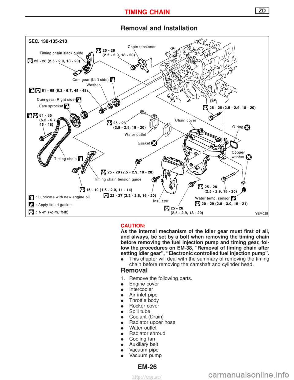
Removal and Installation
CAUTION:
As the internal mechanism of the idler gear must first of all,
and always, be set by a bolt when removing the timing chain
before removing the fuel injection pump and timing gear, fol-
low the procedures on EM-38, ªRemoval of timing chain after
setting idler gearº, ªElectronic controlled fuel injection pumpº.
IThis chapter will deal with the summary of removing the timing
chain before removing the camshaft and cylinder head.
Removal
1. Remove the following parts.
IEngine cover
I Intercooler
I Air inlet pipe
I Throttle body
I Rocker cover
I Spill tube
I Coolant (Drain)
I Radiator upper hose
I Water outlet
I Radiator shroud
I Cooling fan
I Auxiliary belt
I Vacuum pipe
I Vacuum pump
YEM028
TIMING CHAINZD
EM-26
http://vnx.su/
Page 154 of 1833
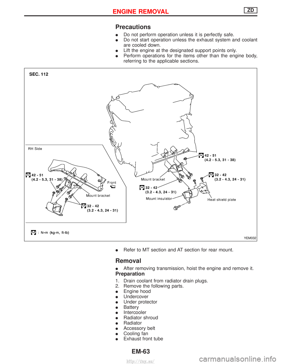
Precautions
IDo not perform operation unless it is perfectly safe.
I Do not start operation unless the exhaust system and coolant
are cooled down.
I Lift the engine at the designated support points only.
I Perform operations for the items other than the engine body,
referring to the applicable sections.
I Refer to MT section and AT section for rear mount.
Removal
IAfter removing transmission, hoist the engine and remove it.
Preparation
1. Drain coolant from radiator drain plugs.
2. Remove the following parts.
IEngine hood
I Undercover
I Under protector
I Battery
I Intercooler
I Radiator shroud
I Radiator
I Accessory belt
I Cooling fan
I Exhaust front tube
YEM032
ENGINE REMOVALZD
EM-63
http://vnx.su/
Page 155 of 1833
Engine room (Left)
3. Remove air duct and air cleaner case.
4. Disconnect vacuum hose to the vehicle on the engine.
5. Disconnect harness connectors from alternator and air com-pressor.
6. Remove alternator.
7. After removing refrigerant, remove pipes of air compressor and inlet/outlet.
8. Disconnect heating hose, install blank cap to hose to prevent coolant from leaking.
9. Remove heating pipe.
10. Remove heat insulator.
11. Remove catalytic converter.
Engine room (Right)
12. Remove power steering reservoir tank from bracket, and fix it to the vehicle with a rope.
CAUTION:
Keep the reservoir tank level when fixing to prevent oil leak.
13. Remove fuel feed and return hoses.
CAUTION:
Install blank caps immediately to avoid fuel leakage.
14. Remove all harness connectors on the engine, and move har- nesses to the side of the vehicle.
Vehicle underfloor
15. Remove starter motor.
16. Detach A/T oil cooler pipes from oil pan. (A/T model)
17. Remove rear propeller shaft.
18. Remove mounting bolts to secure the engine to transmission.
1) Remove torque converter installation bolt. (A/T model)
2) Lift transmission bottom with transmission jack, and removerear mount members from the vehicle.
3) Lower transmission with the jack, and remove upper mounting bolts securing the engine to transmission.
4) Lift transmission with the jack, and reinstall rear mount mem- bers to the vehicle.
5) Position the jack to the front side of transmission.
6) Remove remaining mounting bolts securing the engine to trans- mission.
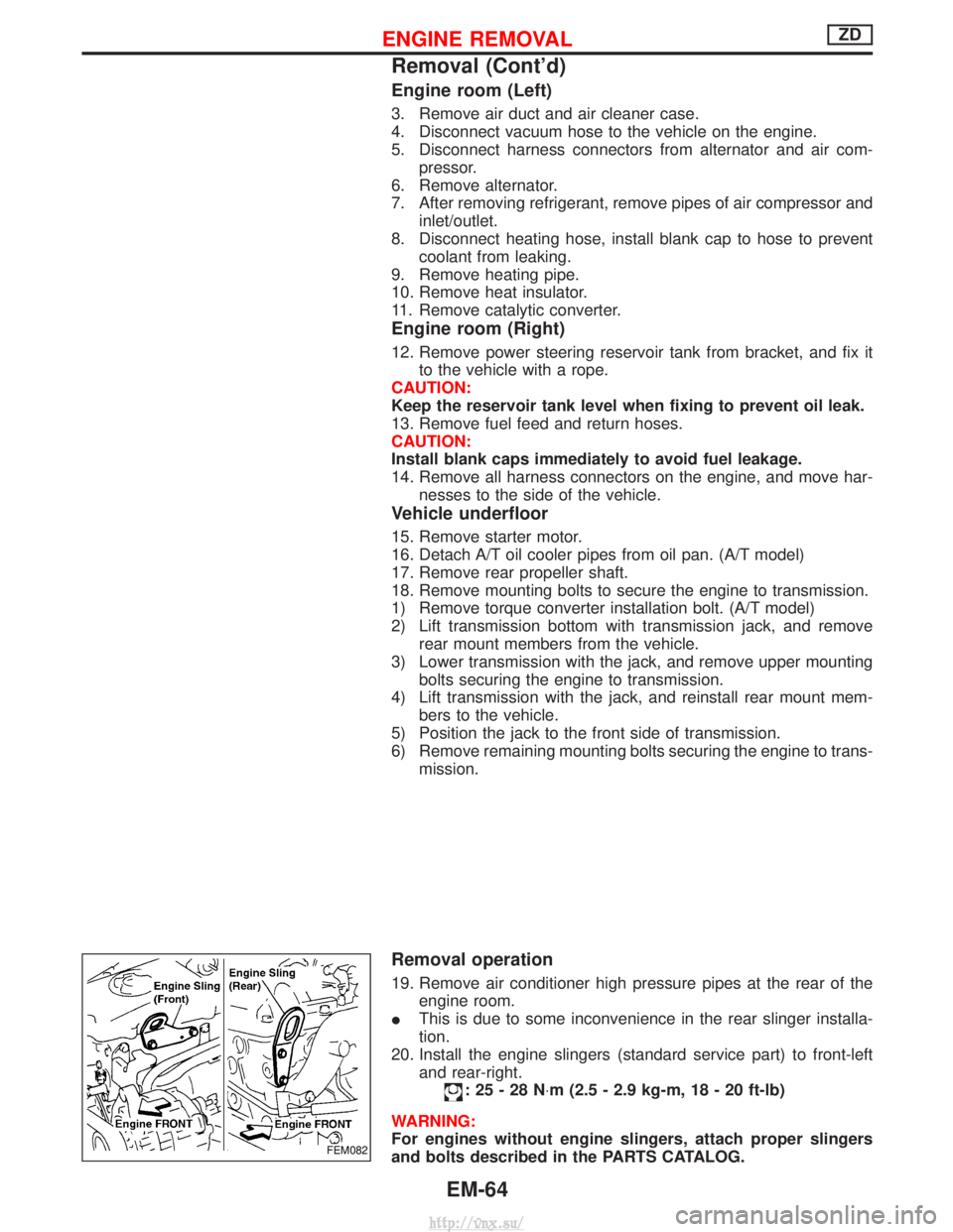
Removal operation
19. Remove air conditioner high pressure pipes at the rear of theengine room.
I This is due to some inconvenience in the rear slinger installa-
tion.
20. Install the engine slingers (standard service part) to front-left and rear-right.
:25-28N ×m (2.5 - 2.9 kg-m, 18 - 20 ft-lb)
WARNING:
For engines without engine slingers, attach proper slingers
and bolts described in the PARTS CATALOG.
FEM082
ENGINE REMOVALZD
Removal (Cont'd)
EM-64
http://vnx.su/
Page 156 of 1833
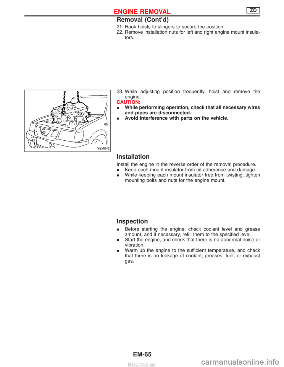
21. Hook hoists to slingers to secure the position.
22. Remove installation nuts for left and right engine mount insula-tors.
23. While adjusting position frequently, hoist and remove the engine.
CAUTION:
I While performing operation, check that all necessary wires
and pipes are disconnected.
I Avoid interference with parts on the vehicle.
Installation
Install the engine in the reverse order of the removal procedure.
IKeep each mount insulator from oil adherence and damage.
I While keeping each mount insulator free from twisting, tighten
mounting bolts and nuts for the engine mount.
Inspection
IBefore starting the engine, check coolant level and grease
amount, and if necessary, refill them to the specified level.
I Start the engine, and check that there is no abnormal noise or
vibration.
I Warm up the engine to the sufficient temperature, and check
that there is no leakage of coolant, greases, fuel, or exhaust
gas.
YEM042
ENGINE REMOVALZD
Removal (Cont'd)
EM-65
http://vnx.su/
Page 159 of 1833
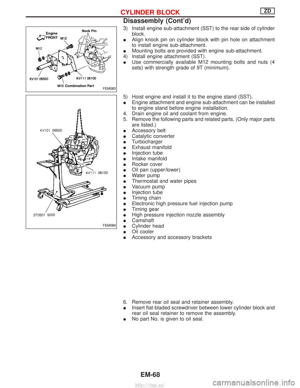
3) Install engine sub-attachment (SST) to the rear side of cylinderblock.
I Align knock pin on cylinder block with pin hole on attachment
to install engine sub-attachment.
I Mounting bolts are provided with engine sub-attachment.
4) Install engine attachment (SST).
I Use commercially available M12 mounting bolts and nuts (4
sets) with strength grade of 9T (minimum).
5) Hoist engine and install it to the engine stand (SST).
I Engine attachment and engine sub-attachment can be installed
to engine stand before engine installation.
4. Drain engine oil and coolant from engine.
5. Remove the following parts and related parts. (Only major parts are listed.)
I Accessory belt
I Catalytic converter
I Turbocharger
I Exhaust manifold
I Injection tube
I Intake manifold
I Rocker cover
I Oil pan (upper/lower)
I Water pump
I Thermostat and water pipes
I Vacuum pump
I Injection tube
I Timing chain
I Electronic high pressure fuel injection pump
I Timing gear
I High pressure injection nozzle assembly
I Camshaft
I Cylinder head
I Oil cooler
I Accessory and accessory brackets
6. Remove rear oil seal and retainer assembly.
I Insert flat-bladed screwdriver between lower cylinder block and
rear oil seal retainer to remove the assembly.
I No part No. is given to oil seal.
FEM083
FEM084
CYLINDER BLOCKZD
Disassembly (Cont'd)
EM-68
http://vnx.su/
Page 165 of 1833
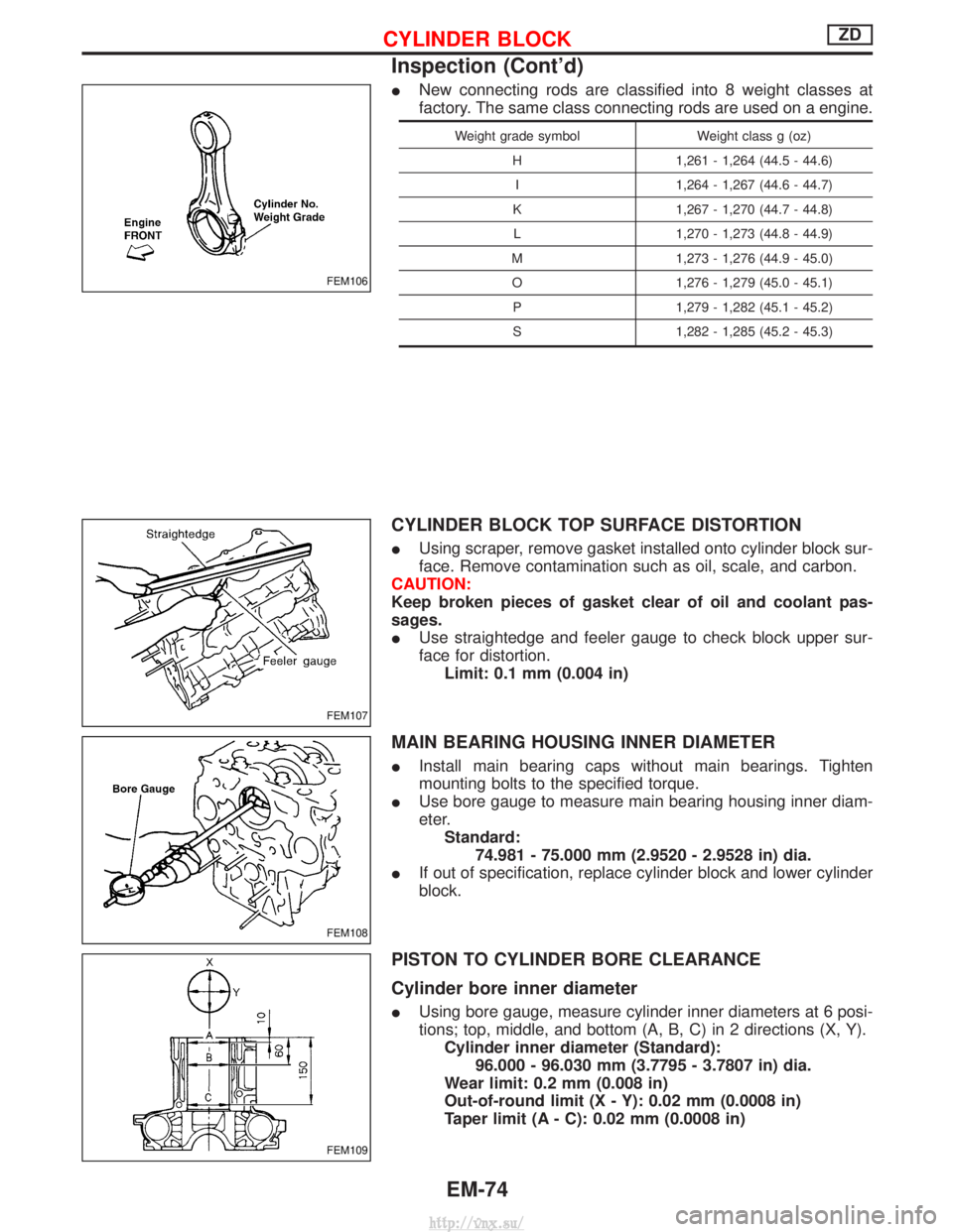
INew connecting rods are classified into 8 weight classes at
factory. The same class connecting rods are used on a engine.
Weight grade symbol Weight class g (oz)
H 1,261 - 1,264 (44.5 - 44.6) I 1,264 - 1,267 (44.6 - 44.7)
K 1,267 - 1,270 (44.7 - 44.8) L 1,270 - 1,273 (44.8 - 44.9)
M 1,273 - 1,276 (44.9 - 45.0) O 1,276 - 1,279 (45.0 - 45.1) P 1,279 - 1,282 (45.1 - 45.2)
S 1,282 - 1,285 (45.2 - 45.3)
CYLINDER BLOCK TOP SURFACE DISTORTION
I Using scraper, remove gasket installed onto cylinder block sur-
face. Remove contamination such as oil, scale, and carbon.
CAUTION:
Keep broken pieces of gasket clear of oil and coolant pas-
sages.
I Use straightedge and feeler gauge to check block upper sur-
face for distortion.
Limit: 0.1 mm (0.004 in)
MAIN BEARING HOUSING INNER DIAMETER
I Install main bearing caps without main bearings. Tighten
mounting bolts to the specified torque.
I Use bore gauge to measure main bearing housing inner diam-
eter.
Standard: 74.981 - 75.000 mm (2.9520 - 2.9528 in) dia.
I If out of specification, replace cylinder block and lower cylinder
block.
PISTON TO CYLINDER BORE CLEARANCE
Cylinder bore inner diameter
IUsing bore gauge, measure cylinder inner diameters at 6 posi-
tions; top, middle, and bottom (A, B, C) in 2 directions (X, Y).
Cylinder inner diameter (Standard): 96.000 - 96.030 mm (3.7795 - 3.7807 in) dia.
Wear limit: 0.2 mm (0.008 in)
Out-of-round limit (X - Y): 0.02 mm (0.0008 in)
Taper limit (A - C): 0.02 mm (0.0008 in)
FEM106
FEM107
FEM108
FEM109
CYLINDER BLOCKZD
Inspection (Cont'd)
EM-74
http://vnx.su/
Page 171 of 1833
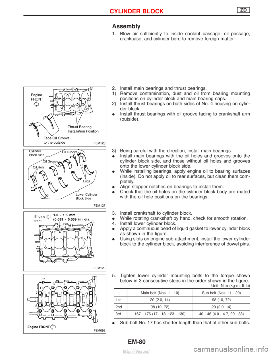
Assembly
1. Blow air sufficiently to inside coolant passage, oil passage,crankcase, and cylinder bore to remove foreign matter.
2. Install main bearings and thrust bearings.
1) Remove contamination, dust and oil from bearing mounting positions on cylinder block and main bearing caps.
2) Install thrust bearings on both sides of No. 4 housing on cylin- der block.
I Install thrust bearings with oil groove facing to crankshaft arm
(outside).
3) Being careful with the direction, install main bearings.
I Install main bearings with the oil holes and grooves onto the
cylinder block side, and those without oil holes and grooves
onto the lower cylinder block side.
I While installing bearings, apply engine oil to bearing surfaces
(inside). Do not apply oil to rear surfaces, but clean them com-
pletely.
I Align stopper notches on bearings to install them.
I Check that the oil holes on the cylinder block body are mated
with the oil hole positions on the bearings.
3. Install crankshaft to cylinder block.
I While rotating crankshaft by hand, check for smooth rotation.
4. Install lower cylinder block.
I Apply a continuous bead of liquid gasket to lower cylinder block
as shown in the figure.
I Using slots on engine sub-attachment, install the lower cylinder
block to the cylinder block, avoiding interference of dowel pins.
5. Tighten lower cylinder mounting bolts to the torque shown below in 3 consecutive steps in the order shown in the figure.
Unit: N ×m (kg-m, ft-lb)
Main bolt (Nos. 1 - 10) Sub-bolt (Nos. 11 - 20)
1st 20 (2.0, 14) 98 (10, 72)
2nd 98 (10, 72) 20 (2.0, 14)
3rd 167 - 176 (17 - 18, 123 - 130) 40 - 46 (4.0 - 4.7, 29 - 33)
I Sub-bolt No. 17 has shorter length than that of other sub-bolts.
FEM126
FEM127
FEM128
FEM092
CYLINDER BLOCKZD
EM-80
http://vnx.su/
Page 186 of 1833
Parts Requiring Angular Tightening
ISome important engine parts are tightened using an angular-
tightening method rather than a torque setting method.
I If these parts are tightened using a torque setting method, dis-
persal of the tightening force (axial bolt force) will be two or
three times that of the dispersal produced by using the correct
angular-tightening method.
I Although the torque setting values (described in this manual)
are equivalent to those used when bolts and nuts are tightened
with an angular-tightening method, they should be used for
reference only.
I To assure the satisfactory maintenance of the engine, bolts and
nuts must be tightened using an angular-tightening method.
I Before tightening the bolts and nuts, ensure that the thread and
seating surfaces are clean and then coated with engine oil.
I The bolts and nuts which require the angular-tightening method
are as follows:
(1) Cylinder head bolts
(2) Connecting rod cap nuts
Liquid Gasket Application Procedure
a. Before applying liquid gasket, use a scraper to remove all
traces of old liquid gasket from mating surface and
grooves, and then completely clean any oil stains from
these portions.
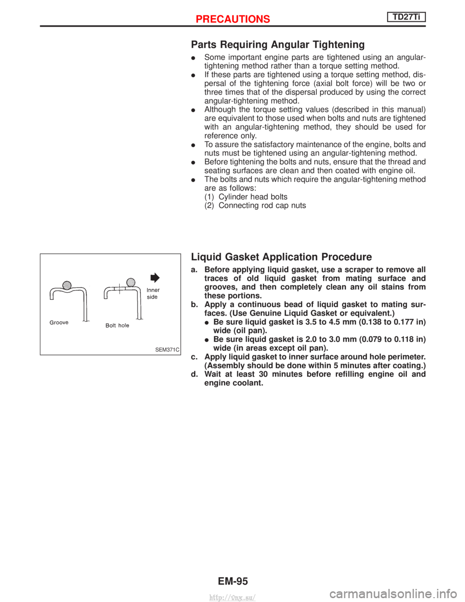
b. Apply a continuous bead of liquid gasket to mating sur- faces. (Use Genuine Liquid Gasket or equivalent.)
IBe sure liquid gasket is 3.5 to 4.5 mm (0.138 to 0.177 in)
wide (oil pan).
I Be sure liquid gasket is 2.0 to 3.0 mm (0.079 to 0.118 in)
wide (in areas except oil pan).
c. Apply liquid gasket to inner surface around hole perimeter. (Assembly should be done within 5 minutes after coating.)
d. Wait at least 30 minutes before refilling engine oil and engine coolant.
SEM371C
PRECAUTIONSTD27Ti
EM-95
http://vnx.su/
Page 196 of 1833
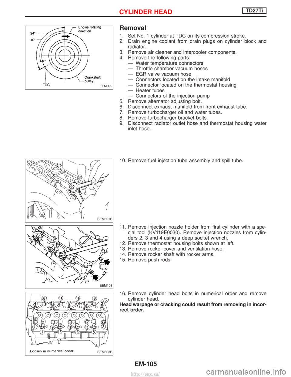
Removal
1. Set No. 1 cylinder at TDC on its compression stroke.
2. Drain engine coolant from drain plugs on cylinder block andradiator.
3. Remove air cleaner and intercooler components.
4. Remove the following parts: Ð Water temperature connectors
Ð Throttle chamber vacuum hoses
Ð EGR valve vacuum hose
Ð Connectors located on the intake manifold
Ð Connector located on the thermostat housing
Ð Heater tubes
Ð Connectors of the injection pump
5. Remove alternator adjusting bolt.
6. Disconnect exhaust manifold from front exhaust tube.
7. Remove turbocharger oil and water tubes.
8. Remove turbocharger bracket bolts.
9. Disconnect radiator outlet hose and thermostat housing water inlet hose.
10. Remove fuel injection tube assembly and spill tube.
11. Remove injection nozzle holder from first cylinder with a spe- cial tool (KV119E0030). Remove injection nozzles from cylin-
ders 2, 3 and 4 using a deep socket wrench.
12. Remove thermostat housing bolts shown at left.
13. Remove rocker cover and ventilation hose.
14. Remove rocker shaft with rocker arms.
15. Remove push rods.
16. Remove cylinder head bolts in numerical order and remove cylinder head.
Head warpage or cracking could result from removing in incor-
rect order.
EEM092
SEM621B
EEM103
SEM623B
CYLINDER HEADTD27Ti
EM-105
http://vnx.su/