ABS NISSAN TERRANO 2004 Service Repair Manual
[x] Cancel search | Manufacturer: NISSAN, Model Year: 2004, Model line: TERRANO, Model: NISSAN TERRANO 2004Pages: 1833, PDF Size: 53.42 MB
Page 29 of 1833
Function and System Application
Diagnostictest mode Function ENGINE A/T Air bag ABS NATS*1
Self-diagnostic results Self-diagnostic results can be read and erased quickly. xxxxx
ECU discriminated No. Classification number of a replacement ECU can be
read to prevent an incorrect ECU from being installed. ÐÐxÐÐ
Data monitor Input/Output data in the ECM can be read. x xÐxÐ
Active test Diagnostic Test Mode in which CONSULT-II drives
some actuators apart from the ECMs and also shifts
some parameters in a specified range. xÐÐxÐ
ECU (ECM) part number ECU (ECM) part number can be read. x xÐxÐ
Control unit initialisation All registered ignition key IDs in NATS components can
be initialised and new IDs can be registered. ÐÐÐÐ x
Self-function check ECM checks its own NATS communication interface. ÐÐÐÐ x
x: Applicable
*1: NATS: Nissan Anti-Theft System
Nickel Metal Hydride Battery Replacement
CONSULT-II contains a nickel metal hydride battery. When replacing the battery obey the following:
WARNING:
Replace the nickel metal hydride battery with genuine CONSULT-II battery only. Use of another battery
may present a risk of fire or explosion. The battery may present a fire or chemical burn hazard if mis-
treated. Do not recharge, disassemble of dispose of in fire.
Keep the battery out of reach of children and discard used battery conforming to the local regulations.
Checking Equipment
When ordering this equipment, contact your NISSAN distributor.
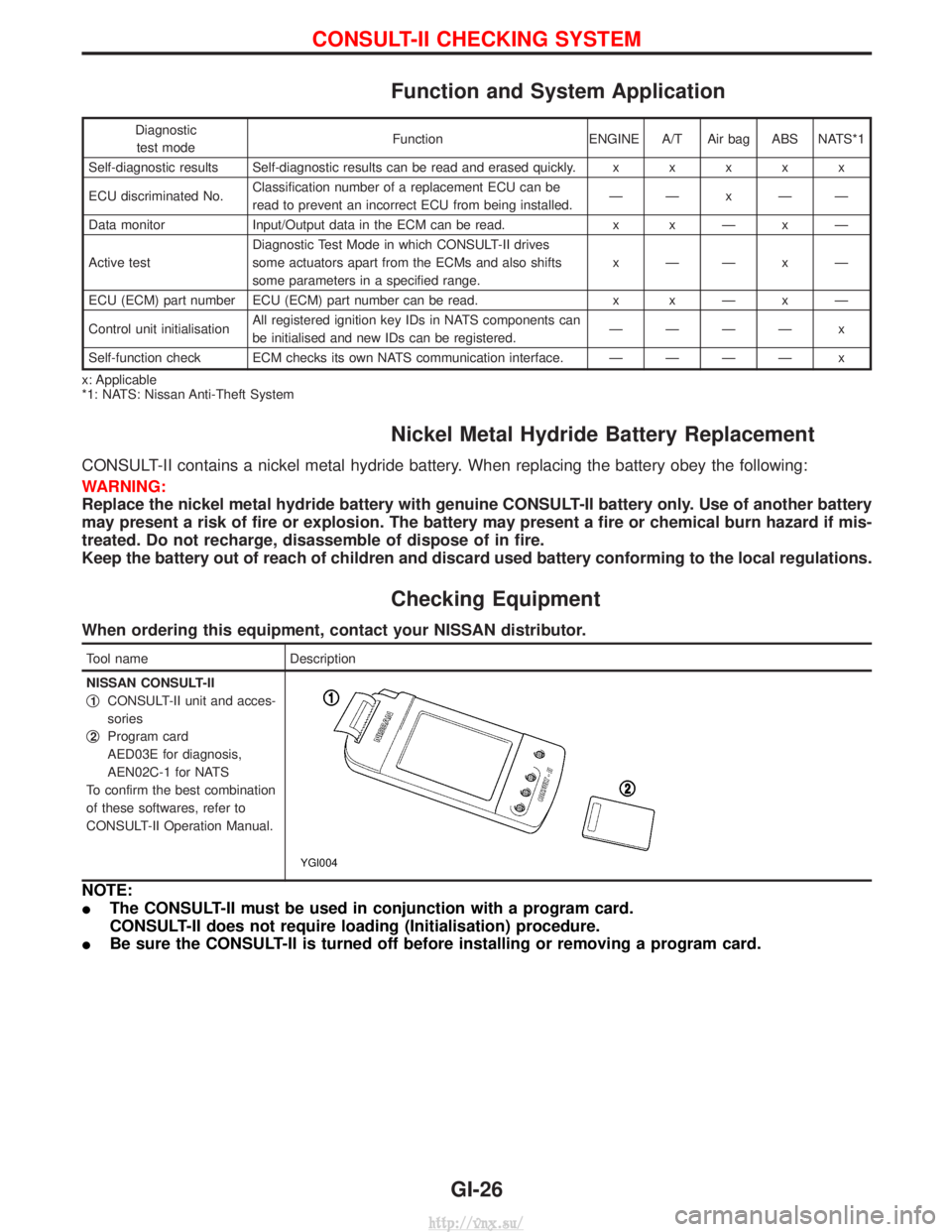
Tool name Description
NISSAN CONSULT-II
q
1CONSULT-II unit and acces-
sories
q
2Program card
AED03E for diagnosis,
AEN02C-1 for NATS
To confirm the best combination
of these softwares, refer to
CONSULT-II Operation Manual.
YGI004
NOTE:
I The CONSULT-II must be used in conjunction with a program card.
CONSULT-II does not require loading (Initialisation) procedure.
I Be sure the CONSULT-II is turned off before installing or removing a program card.
CONSULT-II CHECKING SYSTEM
GI-26
http://vnx.su/
Page 38 of 1833
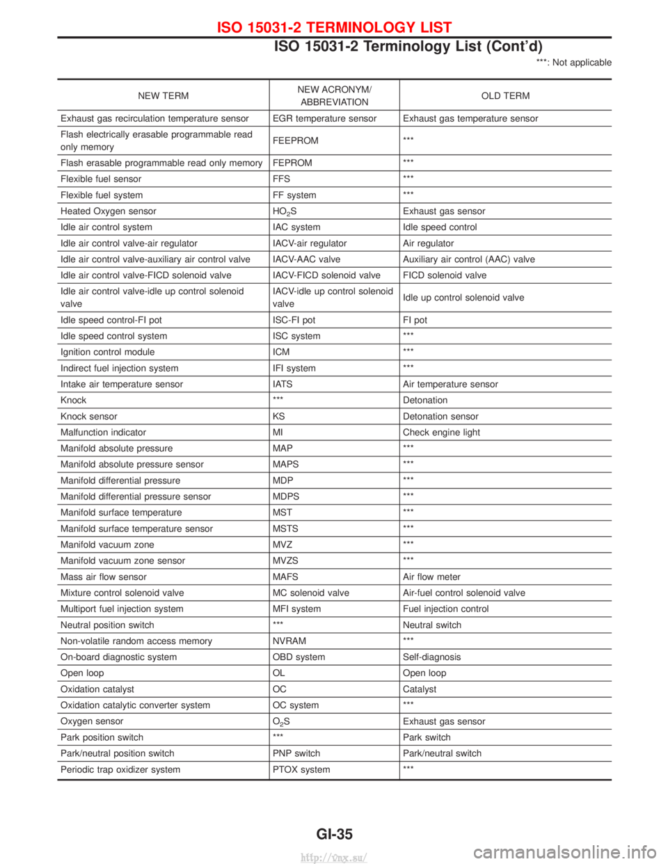
***: Not applicable
NEW TERMNEW ACRONYM/
ABBREVIATION OLD TERM
Exhaust gas recirculation temperature sensor EGR temperature sensor Exhaust gas temperature sensor
Flash electrically erasable programmable read
only memory FEEPROM ***
Flash erasable programmable read only memory FEPROM ***
Flexible fuel sensor FFS ***
Flexible fuel system FF system ***
Heated Oxygen sensor HO
2S Exhaust gas sensor
Idle air control system IAC systemIdle speed control
Idle air control valve-air regulator IACV-air regulatorAir regulator
Idle air control valve-auxiliary air control valve IACV-AAC valve Auxiliary air control (AAC) valve
Idle air control valve-FICD solenoid valve IACV-FICD solenoid valve FICD solenoid valve
Idle air control valve-idle up control solenoid
valve IACV-idle up control solenoid
valve
Idle up control solenoid valve
Idle speed control-FI pot ISC-FI potFI pot
Idle speed control system ISC system***
Ignition control module ICM***
Indirect fuel injection system IFI system***
Intake air temperature sensor IATS Air temperature sensor
Knock *** Detonation
Knock sensor KS Detonation sensor
Malfunction indicator MI Check engine light
Manifold absolute pressure MAP ***
Manifold absolute pressure sensor MAPS ***
Manifold differential pressure MDP ***
Manifold differential pressure sensor MDPS ***
Manifold surface temperature MST ***
Manifold surface temperature sensor MSTS ***
Manifold vacuum zone MVZ ***
Manifold vacuum zone sensor MVZS ***
Mass air flow sensor MAFS Air flow meter
Mixture control solenoid valve MC solenoid valve Air-fuel control solenoid valve
Multiport fuel injection system MFI system Fuel injection control
Neutral position switch *** Neutral switch
Non-volatile random access memory NVRAM ***
On-board diagnostic system OBD system Self-diagnosis
Open loop OL Open loop
Oxidation catalyst OC Catalyst
Oxidation catalytic converter system OC system ***
Oxygen sensor O
2S Exhaust gas sensor
Park position switch ***Park switch
Park/neutral position switch PNP switch Park/neutral switch
Periodic trap oxidizer system PTOX system ***
ISO 15031-2 TERMINOLOGY LIST
ISO 15031-2 Terminology List (Cont'd)
GI-35
http://vnx.su/
Page 64 of 1833
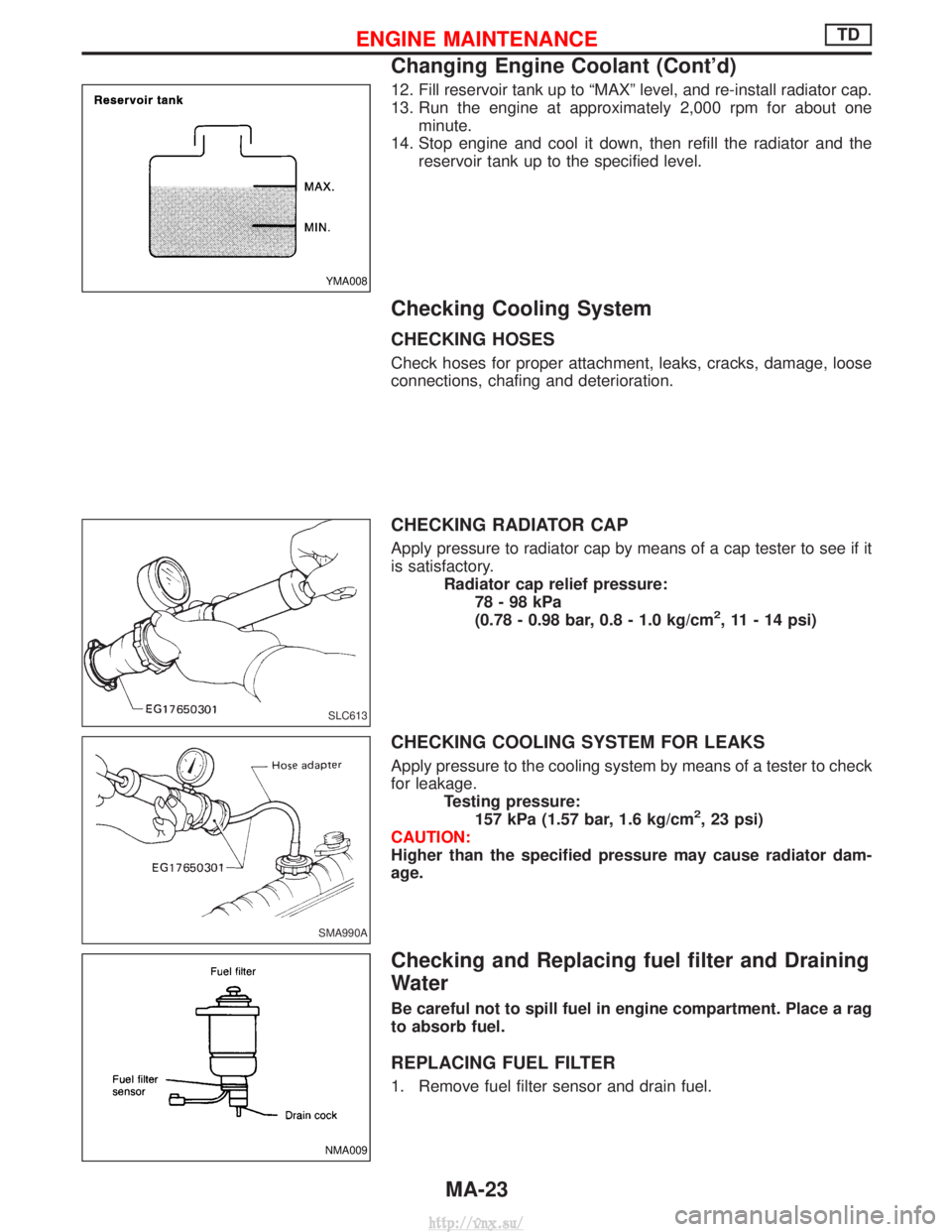
12. Fill reservoir tank up to ªMAXº level, and re-install radiator cap.
13. Run the engine at approximately 2,000 rpm for about oneminute.
14. Stop engine and cool it down, then refill the radiator and the reservoir tank up to the specified level.
Checking Cooling System
CHECKING HOSES
Check hoses for proper attachment, leaks, cracks, damage, loose
connections, chafing and deterioration.
CHECKING RADIATOR CAP
Apply pressure to radiator cap by means of a cap tester to see if it
is satisfactory. Radiator cap relief pressure:78-98kPa
(0.78 - 0.98 bar, 0.8 - 1.0 kg/cm
2, 11 - 14 psi)
CHECKING COOLING SYSTEM FOR LEAKS
Apply pressure to the cooling system by means of a tester to check
for leakage. Testing pressure:157 kPa (1.57 bar, 1.6 kg/cm
2, 23 psi)
CAUTION:
Higher than the specified pressure may cause radiator dam-
age.
Checking and Replacing fuel filter and Draining
Water
Be careful not to spill fuel in engine compartment. Place a rag
to absorb fuel.
REPLACING FUEL FILTER
1. Remove fuel filter sensor and drain fuel.
YMA008
SLC613
SMA990A
NMA009
ENGINE MAINTENANCETD
Changing Engine Coolant (Cont'd)
MA-23
http://vnx.su/
Page 74 of 1833
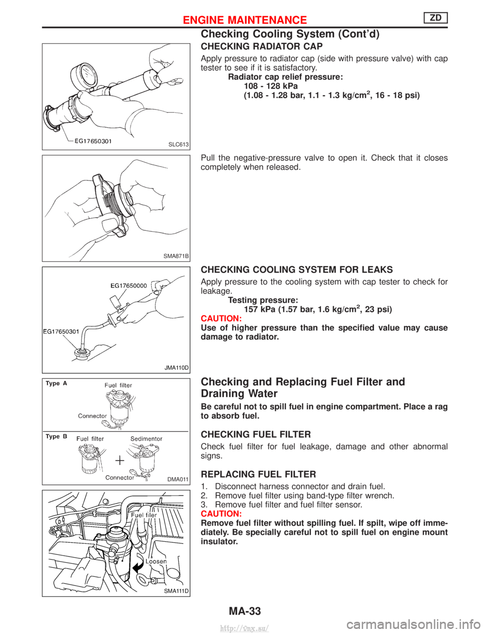
CHECKING RADIATOR CAP
Apply pressure to radiator cap (side with pressure valve) with cap
tester to see if it is satisfactory.Radiator cap relief pressure:108 - 128 kPa
(1.08 - 1.28 bar, 1.1 - 1.3 kg/cm
2, 16 - 18 psi)
Pull the negative-pressure valve to open it. Check that it closes
completely when released.
CHECKING COOLING SYSTEM FOR LEAKS
Apply pressure to the cooling system with cap tester to check for
leakage. Testing pressure:157 kPa (1.57 bar, 1.6 kg/cm
2, 23 psi)
CAUTION:
Use of higher pressure than the specified value may cause
damage to radiator.
Checking and Replacing Fuel Filter and
Draining Water
Be careful not to spill fuel in engine compartment. Place a rag
to absorb fuel.
CHECKING FUEL FILTER
Check fuel filter for fuel leakage, damage and other abnormal
signs.
REPLACING FUEL FILTER
1. Disconnect harness connector and drain fuel.
2. Remove fuel filter using band-type filter wrench.
3. Remove fuel filter and fuel filter sensor.
CAUTION:
Remove fuel filter without spilling fuel. If spilt, wipe off imme-
diately. Be specially careful not to spill fuel on engine mount
insulator.
SLC613
SMA871B
JMA110D
DMA011
SMA111D
ENGINE MAINTENANCEZD
Checking Cooling System (Cont'd)
MA-33
http://vnx.su/
Page 254 of 1833
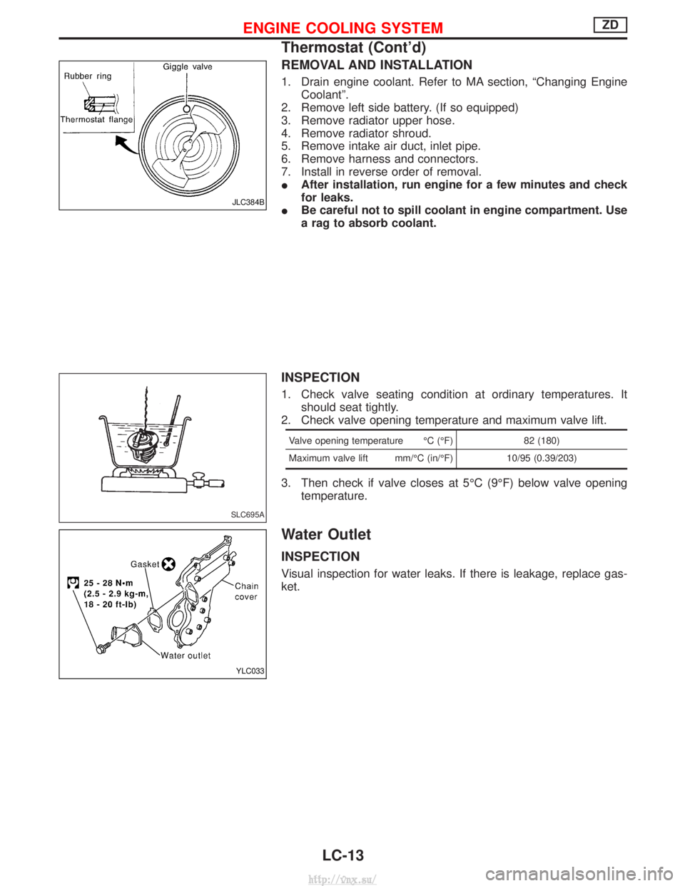
REMOVAL AND INSTALLATION
1. Drain engine coolant. Refer to MA section, ªChanging EngineCoolantº.
2. Remove left side battery. (If so equipped)
3. Remove radiator upper hose.
4. Remove radiator shroud.
5. Remove intake air duct, inlet pipe.
6. Remove harness and connectors.
7. Install in reverse order of removal.
I After installation, run engine for a few minutes and check
for leaks.
I Be careful not to spill coolant in engine compartment. Use
a rag to absorb coolant.
INSPECTION
1. Check valve seating condition at ordinary temperatures. It
should seat tightly.
2. Check valve opening temperature and maximum valve lift.
Valve opening temperature ÉC (ÉF) 82 (180)
Maximum valve lift mm/ÉC (in/ÉF) 10/95 (0.39/203)
3. Then check if valve closes at 5ÉC (9ÉF) below valve opening
temperature.
Water Outlet
INSPECTION
Visual inspection for water leaks. If there is leakage, replace gas-
ket.
JLC384B
SLC695A
YLC033
ENGINE COOLING SYSTEMZD
Thermostat (Cont'd)
LC-13
http://vnx.su/
Page 272 of 1833
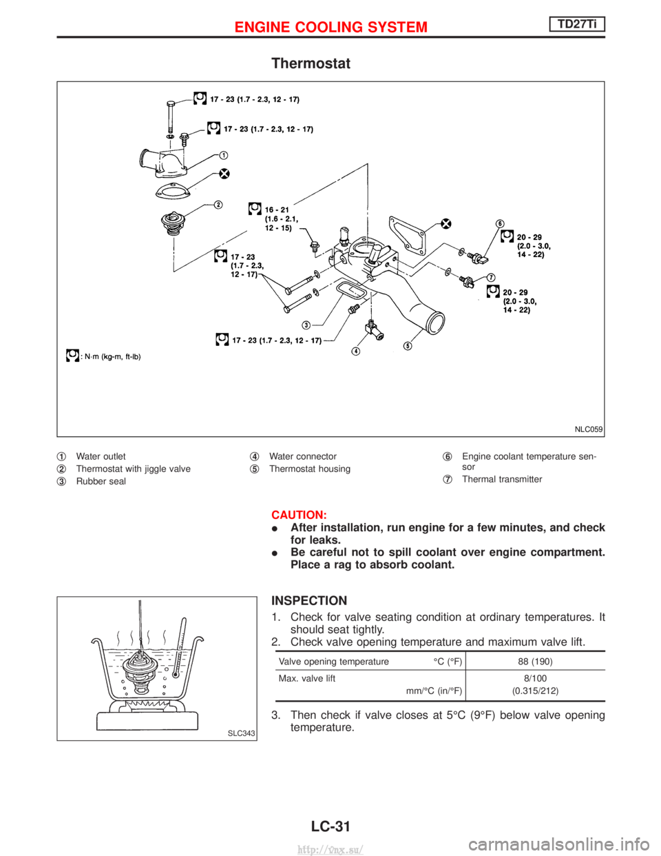
Thermostat
q1Water outlet
q
2Thermostat with jiggle valve
q
3Rubber seal q
4Water connector
q
5Thermostat housing q
6Engine coolant temperature sen-
sor
q
7Thermal transmitter
CAUTION:
I After installation, run engine for a few minutes, and check
for leaks.
I Be careful not to spill coolant over engine compartment.
Place a rag to absorb coolant.
INSPECTION
1. Check for valve seating condition at ordinary temperatures. It
should seat tightly.
2. Check valve opening temperature and maximum valve lift.
Valve opening temperature ÉC (ÉF) 88 (190)
Max. valve lift mm/ÉC (in/ÉF)8/100
(0.315/212)
3. Then check if valve closes at 5ÉC (9ÉF) below valve opening temperature.
NLC059
SLC343
ENGINE COOLING SYSTEMTD27Ti
LC-31
http://vnx.su/
Page 480 of 1833
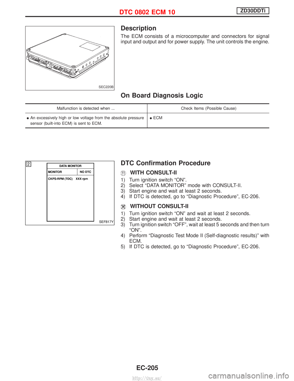
Description
The ECM consists of a microcomputer and connectors for signal
input and output and for power supply. The unit controls the engine.
On Board Diagnosis Logic
Malfunction is detected when ...Check Items (Possible Cause)
I An excessively high or low voltage from the absolute pressure
sensor (built-into ECM) is sent to ECM. I
ECM
DTC Confirmation Procedure
WITH CONSULT-II
1) Turn ignition switch ªONº.
2) Select ªDATA MONITORº mode with CONSULT-II.
3) Start engine and wait at least 2 seconds.
4) If DTC is detected, go to ªDiagnostic Procedureº, EC-206.
WITHOUT CONSULT-II
1) Turn ignition switch ªONº and wait at least 2 seconds.
2) Start engine and wait at least 2 seconds.
3) Turn ignition switch ªOFFº, wait at least 5 seconds and then turn
ªONº.
4) Perform ªDiagnostic Test Mode II (Self-diagnostic results)º with ECM.
5) If DTC is detected, go to ªDiagnostic Procedureº, EC-206.
SEC220B
SEF817Y
DTC 0802 ECM 10ZD30DDTi
EC-205
http://vnx.su/
Page 705 of 1833
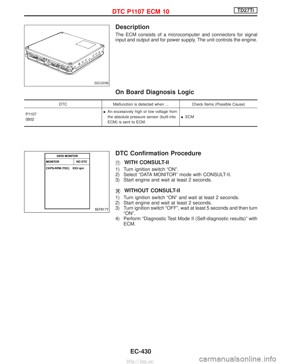
Description
The ECM consists of a microcomputer and connectors for signal
input and output and for power supply. The unit controls the engine.
On Board Diagnosis Logic
DTCMalfunction is detected when ... Check Items (Possible Cause)
P1107
0802 I
An excessively high or low voltage from
the absolute pressure sensor (built-into
ECM) is sent to ECM. I
ECM
DTC Confirmation Procedure
WITH CONSULT-II
1) Turn ignition switch ªONº.
2) Select ªDATA MONITORº mode with CONSULT-II.
3) Start engine and wait at least 2 seconds.
WITHOUT CONSULT-II
1) Turn ignition switch ªONº and wait at least 2 seconds.
2) Start engine and wait at least 2 seconds.
3) Turn ignition switch ªOFFº, wait at least 5 seconds and then turn
ªONº.
4) Perform ªDiagnostic Test Mode II (Self-diagnostic results)º with ECM.
SEC220B
SEF817Y
DTC P1107 ECM 10TD27Ti
EC-430
http://vnx.su/
Page 758 of 1833
WARNING:
When replacing fuel line parts, be sure to observe the following:
IDisplay a ªCAUTION: INFLAMMABLEº sign in workshop.
I Be sure to furnish workshop with a CO
2fire extinguisher service.
I Do not smoke while servicing fuel system. Keep open flames and sparks away from work area.
I Be sure to disconnect battery ground cable before conducting operations.
I Pour drained fuel into an explosion-proof container, then ensure container lid is installed securely.
CAUTION:
I For ECM models, release fuel pressure from fuel line. Refer to EC section (ªFuel Pressure Releaseº,
ªBASIC SERVICE PROCEDUREº).
I Do not disconnect any fuel line unless absolutely necessary.
I Plug hose and pipe openings to prevent entry of dust or dirt.
I Always replace top lid seal and hose clamps with new ones.
I Do not kink or twist hoses and tubes during installation.
I Do not tighten hose clamps excessively because this could cause damage to the hose.
I Ensure fuel check valve is installed in the correct orientation.
I Refer to EC section (ªFUEL CHECK VALVEº, ªEVAPORATIVE EMISSION SYSTEMº).
I After installation, run engine and check for fuel leaks at connections.
Fuel Pump and Gauge
REMOVAL
Petrol engine
1. Release fuel pressure from fuel line.
Refer to EC section (ªFuel Pressure Releaseº, ªBASIC SER-
VICE PROCEDUREº).
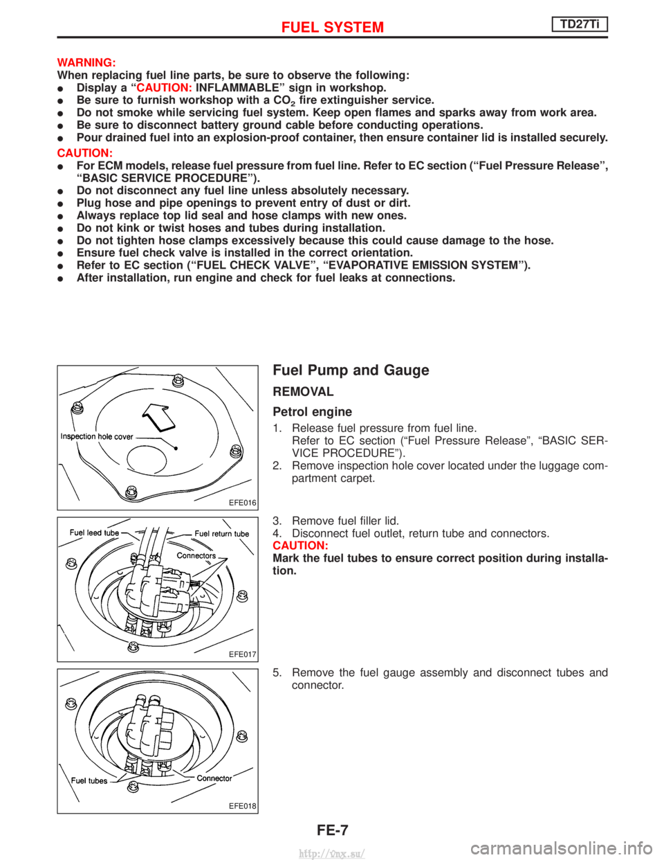
2. Remove inspection hole cover located under the luggage com- partment carpet.
3. Remove fuel filler lid.
4. Disconnect fuel outlet, return tube and connectors.
CAUTION:
Mark the fuel tubes to ensure correct position during installa-
tion.
5. Remove the fuel gauge assembly and disconnect tubes and connector.
EFE016
EFE017
EFE018
FUEL SYSTEMTD27Ti
FE-7
http://vnx.su/
Page 1072 of 1833
To avoid confusion while calculating bearing shims, it is absolutely
necessary to stay with the metric system. If you measure anything
in inches, the results MUST be converted to the metric system.
Drive Pinion Height
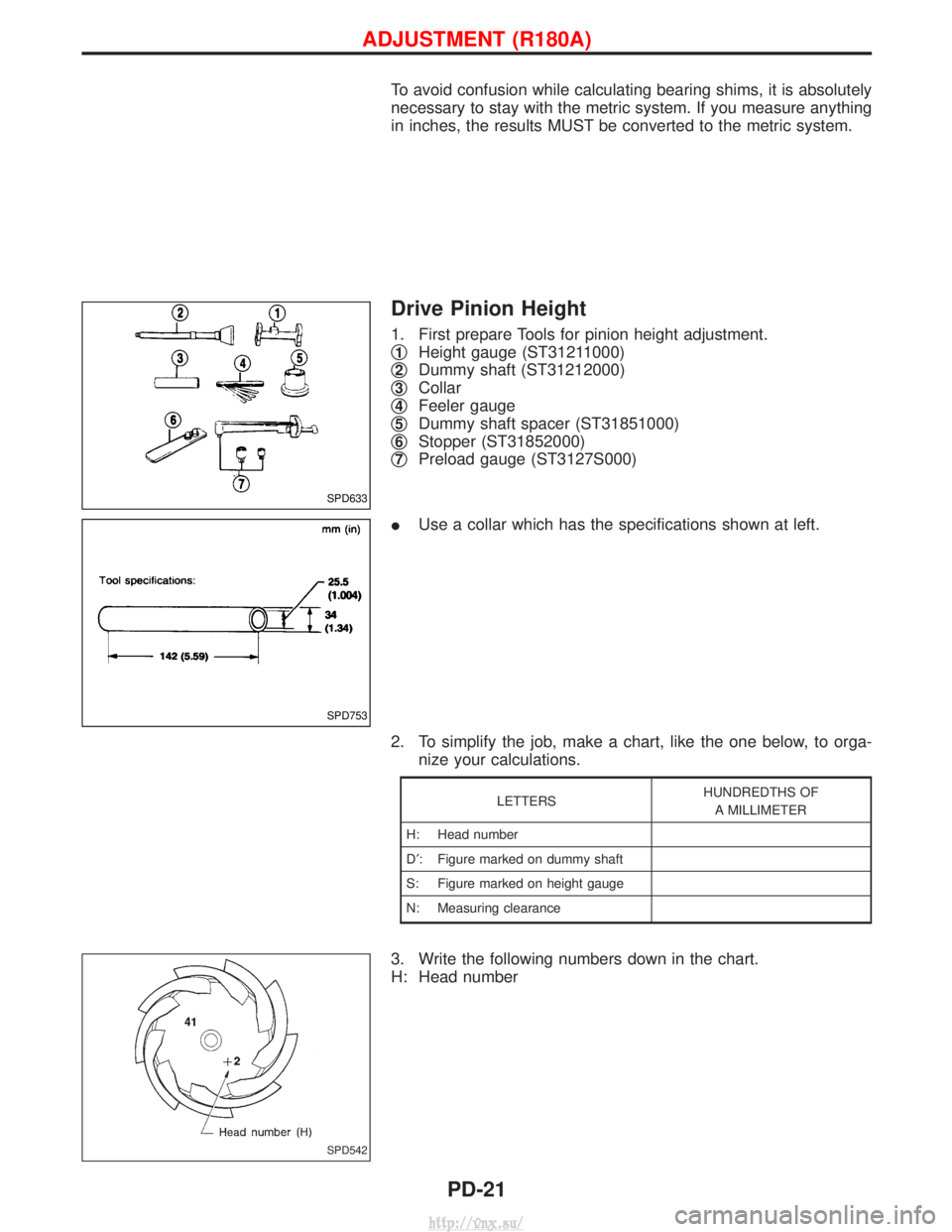
1. First prepare Tools for pinion height adjustment.
q
1Height gauge (ST31211000)
q
2Dummy shaft (ST31212000)
q
3Collar
q
4Feeler gauge
q
5Dummy shaft spacer (ST31851000)
q
6Stopper (ST31852000)
q
7Preload gauge (ST3127S000)
I Use a collar which has the specifications shown at left.
2. To simplify the job, make a chart, like the one below, to orga- nize your calculations.
LETTERS HUNDREDTHS OF
A MILLIMETER
H: Head number
D¢ : Figure marked on dummy shaft
S: Figure marked on height gauge
N: Measuring clearance
3. Write the following numbers down in the chart.
H: Head number
SPD633
SPD753
SPD542
ADJUSTMENT (R180A)
PD-21
http://vnx.su/