data NISSAN TERRANO 2004 Service Repair Manual
[x] Cancel search | Manufacturer: NISSAN, Model Year: 2004, Model line: TERRANO, Model: NISSAN TERRANO 2004Pages: 1833, PDF Size: 53.42 MB
Page 12 of 1833
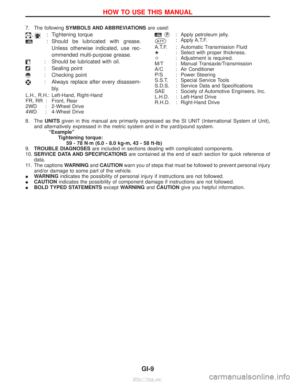
7. The followingSYMBOLS AND ABBREVIATIONS are used:
,: Tightening torque
: Should be lubricated with grease.
Unless otherwise indicated, use rec-
ommended multi-purpose grease.
: Should be lubricated with oil.
: Sealing point
: Checking point
: Always replace after every disassem- bly.
L.H., R.H.: Left-Hand, Right-Hand
FR, RR : Front, Rear
2WD : 2-Wheel Drive
4WD : 4-Wheel Drive
qP: Apply petroleum jelly.
: Apply A.T.F.
A.T.F. : Automatic Transmission Fluid
H : Select with proper thickness.
I : Adjustment is required.
M/T : Manual Transaxle/Transmission
A/C : Air Conditioner
P/S : Power Steering
S.S.T. : Special Service Tools
S.D.S. : Service Data and Specifications
SAE : Society of Automotive Engineers, Inc.
L.H.D. : Left-Hand Drive
R.H.D. : Right-Hand Drive
8. The UNITSgiven in this manual are primarily expressed as the SI UNIT (International System of Unit),
and alternatively expressed in the metric system and in the yard/pound system. ªExampleºTightening torque:59-78N ×m (6.0 - 8.0 kg-m, 43 - 58 ft-lb)
9. TROUBLE DIAGNOSES are included in sections dealing with complicated components.
10. SERVICE DATA AND SPECIFICATIONS are contained at the end of each section for quick reference of
data.
11. The captions WARNINGandCAUTION warn you of steps that must be followed to prevent personal injury
and/or damage to some part of the vehicle.
I WARNING indicates the possibility of personal injury if instructions are not followed.
I CAUTION indicates the possibility of component damage if instructions are not followed.
I BOLD TYPED STATEMENTS exceptWARNING andCAUTION give you helpful information.
HOW TO USE THIS MANUAL
GI-9
http://vnx.su/
Page 29 of 1833
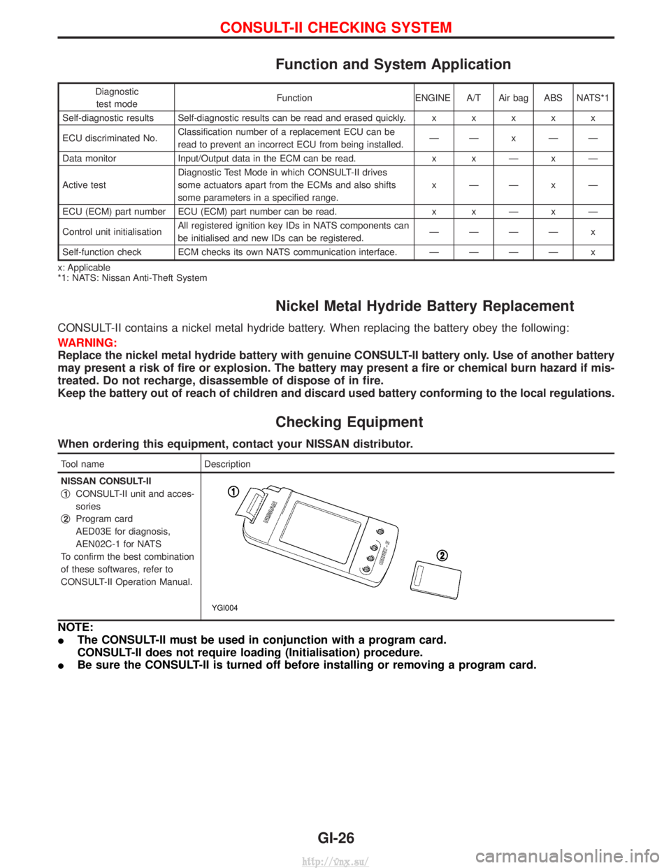
Function and System Application
Diagnostictest mode Function ENGINE A/T Air bag ABS NATS*1
Self-diagnostic results Self-diagnostic results can be read and erased quickly. xxxxx
ECU discriminated No. Classification number of a replacement ECU can be
read to prevent an incorrect ECU from being installed. ÐÐxÐÐ
Data monitor Input/Output data in the ECM can be read. x xÐxÐ
Active test Diagnostic Test Mode in which CONSULT-II drives
some actuators apart from the ECMs and also shifts
some parameters in a specified range. xÐÐxÐ
ECU (ECM) part number ECU (ECM) part number can be read. x xÐxÐ
Control unit initialisation All registered ignition key IDs in NATS components can
be initialised and new IDs can be registered. ÐÐÐÐ x
Self-function check ECM checks its own NATS communication interface. ÐÐÐÐ x
x: Applicable
*1: NATS: Nissan Anti-Theft System
Nickel Metal Hydride Battery Replacement
CONSULT-II contains a nickel metal hydride battery. When replacing the battery obey the following:
WARNING:
Replace the nickel metal hydride battery with genuine CONSULT-II battery only. Use of another battery
may present a risk of fire or explosion. The battery may present a fire or chemical burn hazard if mis-
treated. Do not recharge, disassemble of dispose of in fire.
Keep the battery out of reach of children and discard used battery conforming to the local regulations.
Checking Equipment
When ordering this equipment, contact your NISSAN distributor.
Tool name Description
NISSAN CONSULT-II
q
1CONSULT-II unit and acces-
sories
q
2Program card
AED03E for diagnosis,
AEN02C-1 for NATS
To confirm the best combination
of these softwares, refer to
CONSULT-II Operation Manual.
YGI004
NOTE:
I The CONSULT-II must be used in conjunction with a program card.
CONSULT-II does not require loading (Initialisation) procedure.
I Be sure the CONSULT-II is turned off before installing or removing a program card.
CONSULT-II CHECKING SYSTEM
GI-26
http://vnx.su/
Page 37 of 1833
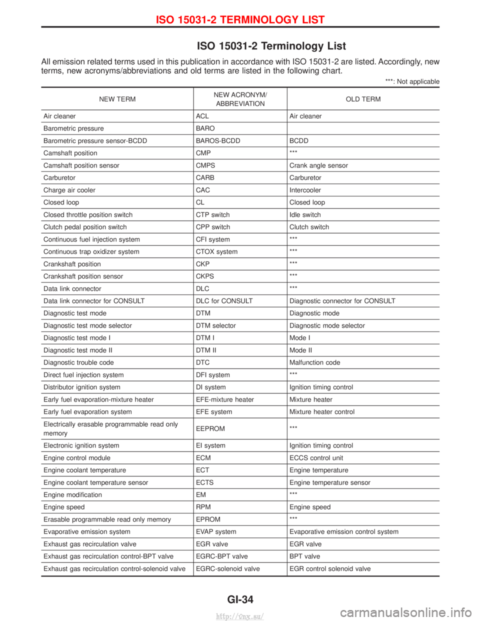
ISO 15031-2 Terminology List
All emission related terms used in this publication in accordance with ISO 15031-2 are listed. Accordingly, new
terms, new acronyms/abbreviations and old terms are listed in the following chart.
***: Not applicable
NEW TERMNEW ACRONYM/
ABBREVIATION OLD TERM
Air cleaner ACL Air cleaner
Barometric pressure BARO
Barometric pressure sensor-BCDD BAROS-BCDD BCDD
Camshaft position CMP ***
Camshaft position sensor CMPS Crank angle sensor
Carburetor CARB Carburetor
Charge air cooler CAC Intercooler
Closed loop CL Closed loop
Closed throttle position switch CTP switch Idle switch
Clutch pedal position switch CPP switch Clutch switch
Continuous fuel injection system CFI system ***
Continuous trap oxidizer system CTOX system ***
Crankshaft position CKP ***
Crankshaft position sensor CKPS ***
Data link connector DLC ***
Data link connector for CONSULT DLC for CONSULT Diagnostic connector for CONSULT
Diagnostic test mode DTM Diagnostic mode
Diagnostic test mode selector DTM selector Diagnostic mode selector
Diagnostic test mode I DTM I Mode I
Diagnostic test mode II DTM II Mode II
Diagnostic trouble code DTC Malfunction code
Direct fuel injection system DFI system ***
Distributor ignition system DI system Ignition timing control
Early fuel evaporation-mixture heater EFE-mixture heater Mixture heater
Early fuel evaporation system EFE system Mixture heater control
Electrically erasable programmable read only
memory EEPROM ***
Electronic ignition system EI system Ignition timing control
Engine control module ECM ECCS control unit
Engine coolant temperature ECT Engine temperature
Engine coolant temperature sensor ECTS Engine temperature sensor
Engine modification EM ***
Engine speed RPM Engine speed
Erasable programmable read only memory EPROM ***
Evaporative emission system EVAP system Evaporative emission control system
Exhaust gas recirculation valve EGR valve EGR valve
Exhaust gas recirculation control-BPT valve EGRC-BPT valve BPT valve
Exhaust gas recirculation control-solenoid valve EGRC-solenoid valve EGR control solenoid valve
ISO 15031-2 TERMINOLOGY LIST
GI-34
http://vnx.su/
Page 92 of 1833
ENGINE MECHANICAL
SECTION
EM
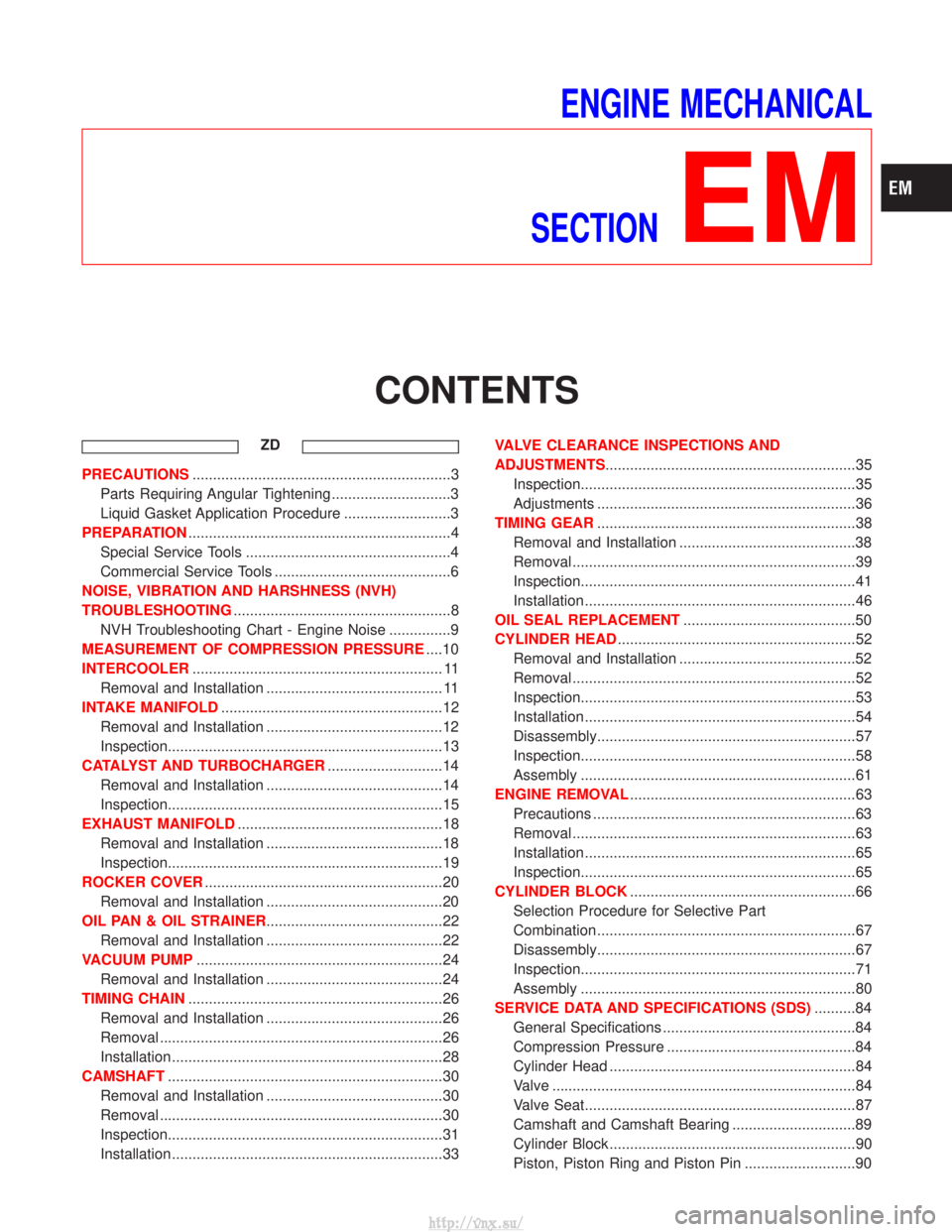
CONTENTS
ZD
PRECAUTIONS ...............................................................3
Parts Requiring Angular Tightening .............................3
Liquid Gasket Application Procedure ..........................3
PREPARATION ................................................................4
Special Service Tools ..................................................4
Commercial Service Tools ...........................................6
NOISE, VIBRATION AND HARSHNESS (NVH)
TROUBLESHOOTING .....................................................8
NVH Troubleshooting Chart - Engine Noise ...............9
MEASUREMENT OF COMPRESSION PRESSURE ....10
INTERCOOLER ............................................................. 11
Removal and Installation ........................................... 11
INTAKE MANIFOLD ......................................................12
Removal and Installation ...........................................12
Inspection...................................................................13
CATALYST AND TURBOCHARGER ............................14
Removal and Installation ...........................................14
Inspection...................................................................15
EXHAUST MANIFOLD ..................................................18
Removal and Installation ...........................................18
Inspection...................................................................19
ROCKER COVER ..........................................................20
Removal and Installation ...........................................20
OIL PAN & OIL STRAINER ...........................................22
Removal and Installation ...........................................22
VACUUM PUMP ............................................................24
Removal and Installation ...........................................24
TIMING CHAIN ..............................................................26
Removal and Installation ...........................................26
Removal .....................................................................26
Installation ..................................................................28
CAMSHAFT ...................................................................30
Removal and Installation ...........................................30
Removal .....................................................................30
Inspection...................................................................31
Installation ..................................................................33 VALVE CLEARANCE INSPECTIONS AND
ADJUSTMENTS
.............................................................35
Inspection...................................................................35
Adjustments ...............................................................36
TIMING GEAR ...............................................................38
Removal and Installation ...........................................38
Removal .....................................................................39
Inspection...................................................................41
Installation ..................................................................46
OIL SEAL REPLACEMENT ..........................................50
CYLINDER HEAD ..........................................................52
Removal and Installation ...........................................52
Removal .....................................................................52
Inspection...................................................................53
Installation ..................................................................54
Disassembly...............................................................57
Inspection...................................................................58
Assembly ...................................................................61
ENGINE REMOVAL .......................................................63
Precautions ................................................................63
Removal .....................................................................63
Installation ..................................................................65
Inspection...................................................................65
CYLINDER BLOCK .......................................................66
Selection Procedure for Selective Part
Combination ...............................................................67
Disassembly...............................................................67
Inspection...................................................................71
Assembly ...................................................................80
SERVICE DATA AND SPECIFICATIONS (SDS) ..........84
General Specifications ...............................................84
Compression Pressure ..............................................84
Cylinder Head ............................................................84
Valve ........................................................................\
..84
Valve Seat..................................................................87
Camshaft and Camshaft Bearing ..............................89
Cylinder Block ............................................................90
Piston, Piston Ring and Piston Pin ...........................90
http://vnx.su/
Page 93 of 1833
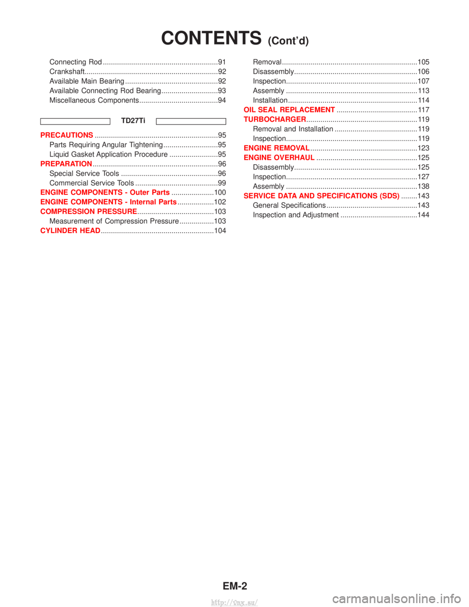
Connecting Rod .........................................................91
Crankshaft..................................................................92
Available Main Bearing ..............................................92
Available Connecting Rod Bearing............................93
Miscellaneous Components.......................................94TD27Ti
PRECAUTIONS.............................................................95
Parts Requiring Angular Tightening ...........................95
Liquid Gasket Application Procedure ........................95
PREPARATION ..............................................................96
Special Service Tools ................................................96
Commercial Service Tools .........................................99
ENGINE COMPONENTS - Outer Parts .....................100
ENGINE COMPONENTS - Internal Parts ..................102
COMPRESSION PRESSURE......................................103 Measurement of Compression Pressure .................103
CYLINDER HEAD ........................................................104 Removal ...................................................................105
Disassembly.............................................................106
Inspection.................................................................107
Assembly ................................................................. 113
Installation ................................................................ 114
OIL SEAL REPLACEMENT ........................................ 117
TURBOCHARGER ....................................................... 119
Removal and Installation ......................................... 119
Inspection................................................................. 119
ENGINE REMOVAL .....................................................123
ENGINE OVERHAUL ..................................................125
Disassembly.............................................................125
Inspection.................................................................127
Assembly .................................................................138
SERVICE DATA AND SPECIFICATIONS (SDS) ........143
General Specifications .............................................143
Inspection and Adjustment ......................................144
CONTENTS(Cont'd)
EM-2
http://vnx.su/
Page 152 of 1833
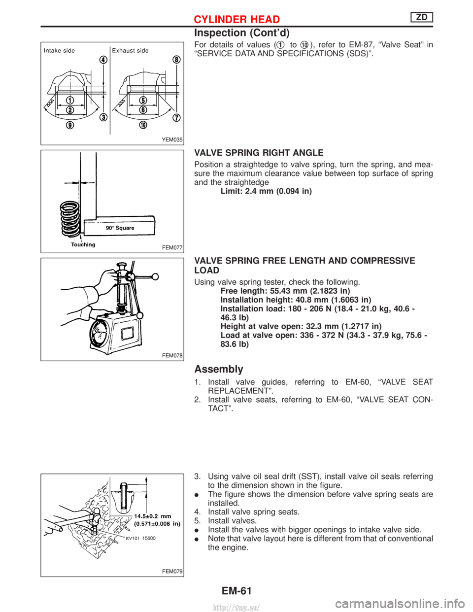
For details of values (q1toq10), refer to EM-87, ªValve Seatº in
ªSERVICE DATA AND SPECIFICATIONS (SDS)º.
VALVE SPRING RIGHT ANGLE
Position a straightedge to valve spring, turn the spring, and mea-
sure the maximum clearance value between top surface of spring
and the straightedge Limit: 2.4 mm (0.094 in)
VALVE SPRING FREE LENGTH AND COMPRESSIVE
LOAD
Using valve spring tester, check the following.Free length: 55.43 mm (2.1823 in)
Installation height: 40.8 mm (1.6063 in)
Installation load: 180 - 206 N (18.4 - 21.0 kg, 40.6 -
46.3 lb)
Height at valve open: 32.3 mm (1.2717 in)
Load at valve open: 336 - 372 N (34.3 - 37.9 kg, 75.6 -
83.6 lb)
Assembly
1. Install valve guides, referring to EM-60, ªVALVE SEATREPLACEMENTº.
2. Install valve seats, referring to EM-60, ªVALVE SEAT CON- TACTº.
3. Using valve oil seal drift (SST), install valve oil seals referring to the dimension shown in the figure.
I The figure shows the dimension before valve spring seats are
installed.
4. Install valve spring seats.
5. Install valves.
I Install the valves with bigger openings to intake valve side.
I Note that valve layout here is different from that of conventional
the engine.
YEM035
FEM077
FEM078
FEM079
CYLINDER HEADZD
Inspection (Cont'd)
EM-61
http://vnx.su/
Page 175 of 1833
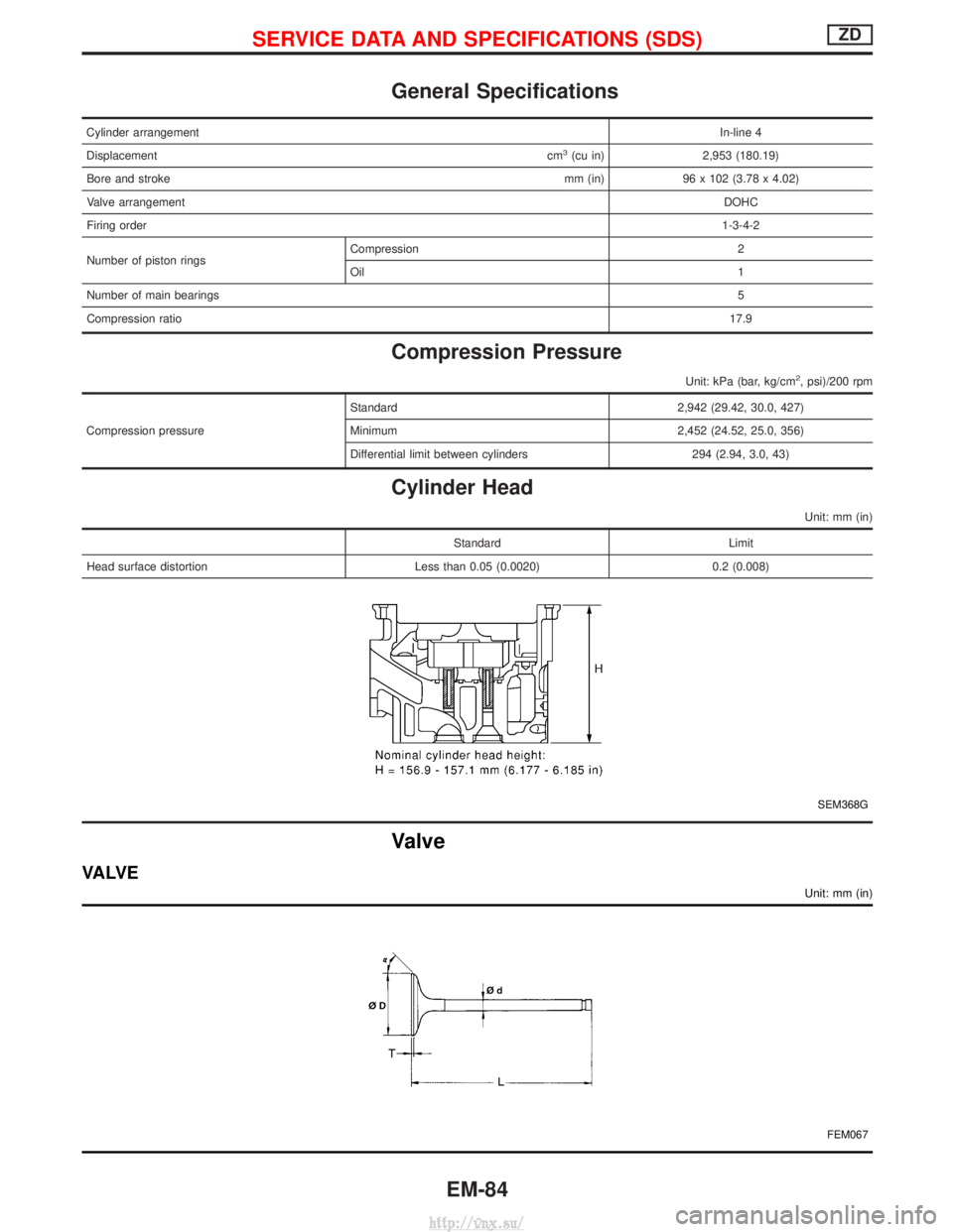
General Specifications
Cylinder arrangementIn-line 4
Displacement cm
3(cu in)2,953 (180.19)
Bore and stroke mm (in) 96 x 102 (3.78 x 4.02)
Valve arrangement DOHC
Firing order 1-3-4-2
Number of piston rings Compression 2
Oil
1
Number of main bearings 5
Compression ratio 17.9
Compression Pressure
Unit: kPa (bar, kg/cm2, psi)/200 rpm
Compression pressureStandard 2,942 (29.42, 30.0, 427)
Minimum 2,452 (24.52, 25.0, 356)
Differential limit between cylinders 294 (2.94, 3.0, 43)
Cylinder Head
Unit: mm (in)
Standard
Limit
Head surface distortion Less than 0.05 (0.0020) 0.2 (0.008)
SEM368G
Valve
VA LV E
Unit: mm (in)
FEM067
SERVICE DATA AND SPECIFICATIONS (SDS)ZD
EM-84
http://vnx.su/
Page 176 of 1833
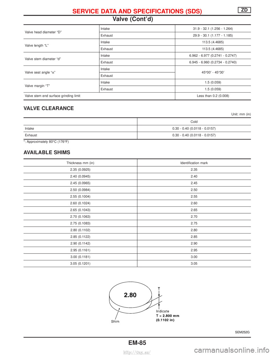
Valve head diameter ªDºIntake 31.9 - 32.1 (1.256 - 1.264)
Exhaust 29.9 - 30.1 (1.177 - 1.185)
Valve length ªLº Intake 113.5 (4.4685)
Exhaust 113.5 (4.4685)
Valve stem diameter ªdº Intake 6.962 - 6.977 (0.2741 - 0.2747)
Exhaust 6.945 - 6.960 (0.2734 - 0.2740)
Valve seat angle ªa º Intake
45É00¢- 45É30¢
Exhaust
Valve margin ªTº Intake 1.5 (0.059)
Exhaust 1.5 (0.059)
Valve stem end surface grinding limit Less than 0.2 (0.008)
VALVE CLEARANCE
Unit: mm (in)
Cold
Intake 0.30 - 0.40 (0.0118 - 0.0157)
Exhaust 0.30 - 0.40 (0.0118 - 0.0157)
*: Approximately 80ÉC (176ÉF)
AVAILABLE SHIMS
Thickness mm (in) Identification mark
2.35 (0.0925) 2.35
2.40 (0.0945) 2.40
2.45 (0.0965) 2.45
2.50 (0.0984) 2.50
2.55 (0.1004) 2.55
2.60 (0.1024) 2.60
2.65 (0.1043) 2.65
2.70 (0.1063) 2.70
2.75 (0.1083) 2.75
2.80 (0.1102) 2.80
2.85 (0.1122) 2.85
2.90 (0.1142) 2.90
2.95 (0.1161) 2.95
3.00 (0.1181) 3.00
3.05 (0.1201) 3.05
SEM252G
SERVICE DATA AND SPECIFICATIONS (SDS)ZD
Valve (Cont'd)
EM-85
http://vnx.su/
Page 177 of 1833
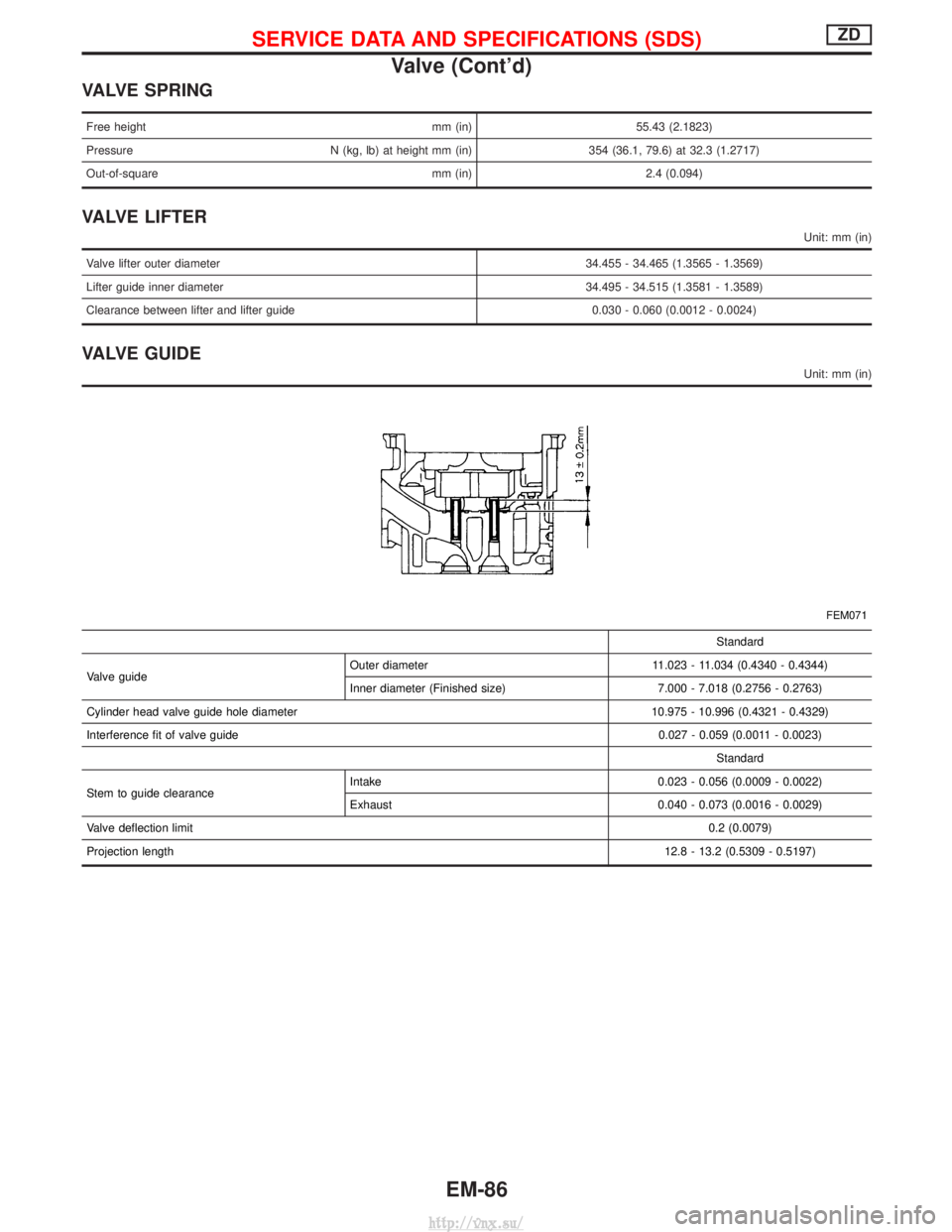
VALVE SPRING
Free heightmm (in)55.43 (2.1823)
Pressure N (kg, lb) at height mm (in) 354 (36.1, 79.6) at 32.3 (1.2717)
Out-of-square mm (in) 2.4 (0.094)
VALVE LIFTER
Unit: mm (in)
Valve lifter outer diameter 34.455 - 34.465 (1.3565 - 1.3569)
Lifter guide inner diameter 34.495 - 34.515 (1.3581 - 1.3589)
Clearance between lifter and lifter guide 0.030 - 0.060 (0.0012 - 0.0024)
VALVE GUIDE
Unit: mm (in)
FEM071
Standard
Valve guide Outer diameter 11.023 - 11.034 (0.4340 - 0.4344)
Inner diameter (Finished size) 7.000 - 7.018 (0.2756 - 0.2763)
Cylinder head valve guide hole diameter 10.975 - 10.996 (0.4321 - 0.4329)
Interference fit of valve guide 0.027 - 0.059 (0.0011 - 0.0023)
Standard
Stem to guide clearance Intake 0.023 - 0.056 (0.0009 - 0.0022)
Exhaust 0.040 - 0.073 (0.0016 - 0.0029)
Valve deflection limit 0.2 (0.0079)
Projection length 12.8 - 13.2 (0.5309 - 0.5197)
SERVICE DATA AND SPECIFICATIONS (SDS)ZD
Valve (Cont'd)
EM-86
http://vnx.su/
Page 178 of 1833
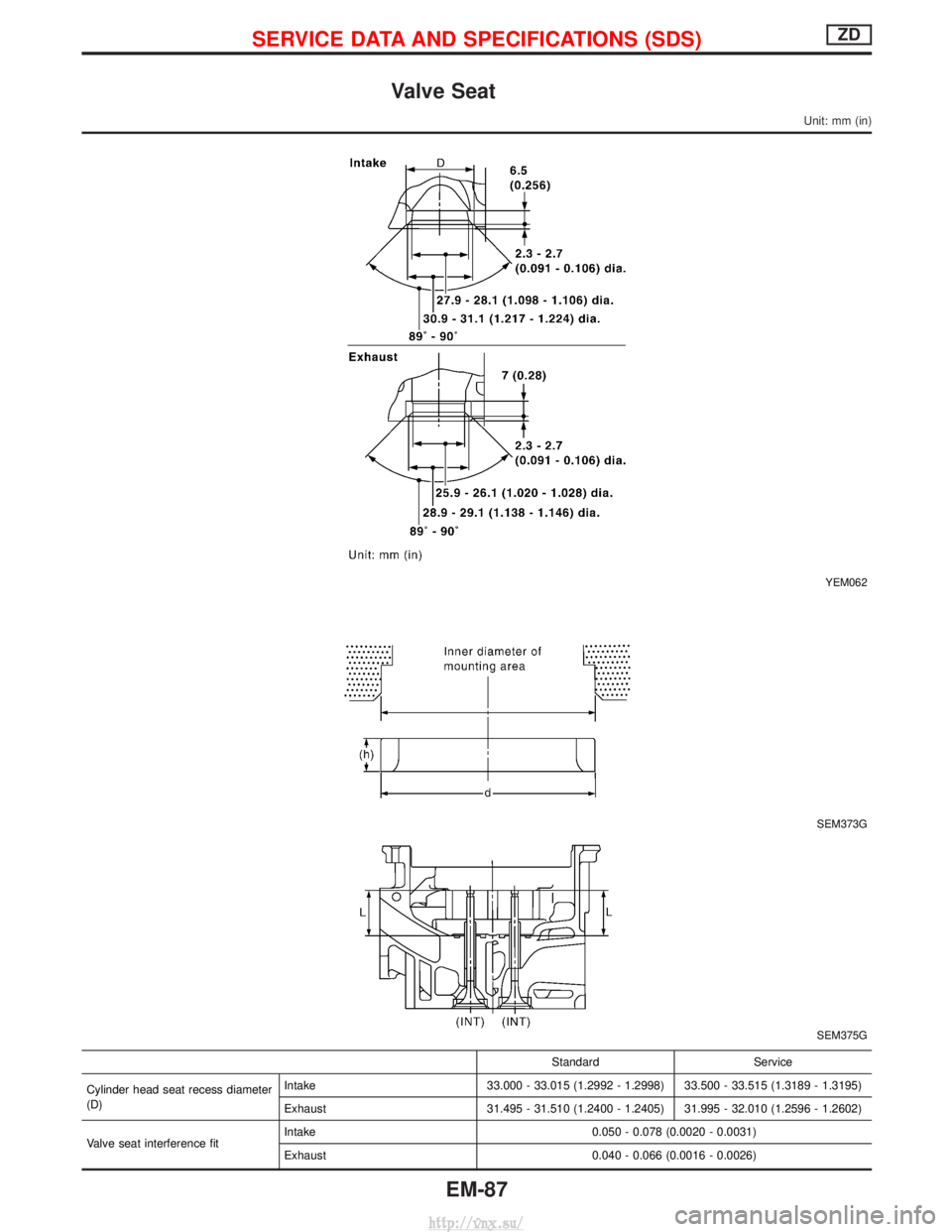
Valve Seat
Unit: mm (in)
YEM062
SEM373G
SEM375G
StandardService
Cylinder head seat recess diameter
(D) Intake
33.000 - 33.015 (1.2992 - 1.2998) 33.500 - 33.515 (1.3189 - 1.3195)
Exhaust 31.495 - 31.510 (1.2400 - 1.2405) 31.995 - 32.010 (1.2596 - 1.2602)
Valve seat interference fit Intake
0.050 - 0.078 (0.0020 - 0.0031)
Exhaust 0.040 - 0.066 (0.0016 - 0.0026)
SERVICE DATA AND SPECIFICATIONS (SDS)ZD
EM-87
http://vnx.su/