hatch NISSAN TIIDA 2007 Service Repair Manual
[x] Cancel search | Manufacturer: NISSAN, Model Year: 2007, Model line: TIIDA, Model: NISSAN TIIDA 2007Pages: 5883, PDF Size: 78.95 MB
Page 3770 of 5883
![NISSAN TIIDA 2007 Service Repair Manual LAN-30
< FUNCTION DIAGNOSIS >[CAN]
CAN COMMUNICATION SYSTEM
FUNCTION DIAGNOSIS
CAN COMMUNICATION SYSTEM
CAN System Specification ChartINFOID:0000000001162800
NOTE:
Refer to LAN-22, "
Trouble Diagnosis NISSAN TIIDA 2007 Service Repair Manual LAN-30
< FUNCTION DIAGNOSIS >[CAN]
CAN COMMUNICATION SYSTEM
FUNCTION DIAGNOSIS
CAN COMMUNICATION SYSTEM
CAN System Specification ChartINFOID:0000000001162800
NOTE:
Refer to LAN-22, "
Trouble Diagnosis](/img/5/57395/w960_57395-3769.png)
LAN-30
< FUNCTION DIAGNOSIS >[CAN]
CAN COMMUNICATION SYSTEM
FUNCTION DIAGNOSIS
CAN COMMUNICATION SYSTEM
CAN System Specification ChartINFOID:0000000001162800
NOTE:
Refer to LAN-22, "
Trouble Diagnosis Procedure" for how to use CAN system specification chart.
Refer to the specification as shown in the chart.
SPECIFICATION CHART A
Determine CAN system type from the following specification chart.
×: Applicable
VEHICLE EQUIPMENT IDENTIFICATION INFORMATION
NOTE:
Body type Hatchback/Sedan
Axle 2WD
Engine K9K HR16DE MR18DE
Transmission M/T A/T M/T
Brake control ABS/ESP
Specification chart SPECIFICATION CHART
ASPECIFICATION CHART BSPECIFICATION CHART
C
Body type Hatchback/Sedan
Axle 2WD
Engine K9K
Transmission M/T
Brake control ABS ESP
Intelligent Key system×× ××
Navigation system××××
CAN system type 12345678
Start CAN Diagnosis
(CONSULT-III)12345678
Page 3771 of 5883
![NISSAN TIIDA 2007 Service Repair Manual LAN
CAN COMMUNICATION SYSTEM
LAN-31
< FUNCTION DIAGNOSIS >[CAN]
C
D
E
F
G
H
I
J
K
L B A
O
P N
Check CAN system type from the vehicle shape and equipment.
SPECIFICATION CHART B
Determine CAN system typ NISSAN TIIDA 2007 Service Repair Manual LAN
CAN COMMUNICATION SYSTEM
LAN-31
< FUNCTION DIAGNOSIS >[CAN]
C
D
E
F
G
H
I
J
K
L B A
O
P N
Check CAN system type from the vehicle shape and equipment.
SPECIFICATION CHART B
Determine CAN system typ](/img/5/57395/w960_57395-3770.png)
LAN
CAN COMMUNICATION SYSTEM
LAN-31
< FUNCTION DIAGNOSIS >[CAN]
C
D
E
F
G
H
I
J
K
L B A
O
P N
Check CAN system type from the vehicle shape and equipment.
SPECIFICATION CHART B
Determine CAN system type from the following specification chart.
×: Applicable
VEHICLE EQUIPMENT IDENTIFICATION INFORMATION
NOTE:
ALMIA0068GB
Body type Hatchback/Sedan
Axle 2WD
Engine HR16DE
Transmission M/T A/T
Brake control ABS ESP ABS ESP
Intelligent Key system×× ×× ×× ××
Navigation system××××××××
CAN system type 9 101112131415161718192021222324
Start CAN Diagnosis
(CONSULT-III)9 101112131415161718192021222324
Page 3772 of 5883
![NISSAN TIIDA 2007 Service Repair Manual LAN-32
< FUNCTION DIAGNOSIS >[CAN]
CAN COMMUNICATION SYSTEM
Check CAN system type from the vehicle shape and equipment.
SPECIFICATION CHART C
Determine CAN system type from the following specification NISSAN TIIDA 2007 Service Repair Manual LAN-32
< FUNCTION DIAGNOSIS >[CAN]
CAN COMMUNICATION SYSTEM
Check CAN system type from the vehicle shape and equipment.
SPECIFICATION CHART C
Determine CAN system type from the following specification](/img/5/57395/w960_57395-3771.png)
LAN-32
< FUNCTION DIAGNOSIS >[CAN]
CAN COMMUNICATION SYSTEM
Check CAN system type from the vehicle shape and equipment.
SPECIFICATION CHART C
Determine CAN system type from the following specification chart.
×: Applicable
VEHICLE EQUIPMENT IDENTIFICATION INFORMATION
NOTE:
ALMIA0068GB
Body type Hatchback/Sedan
Axle 2WD
Engine MR18DE
Transmission M/T
Brake control ABS ESP
Intelligent Key system×× ××
Navigation system××××
CAN system type 25 26 27 28 29 30 31 32
Start CAN Diagnosis
(CONSULT-III)25 26 27 28 29 30 31 32
Page 4364 of 5883

MWI
BCM (BODY CONTROL MODULE)
MWI-57
< ECU DIAGNOSIS >
C
D
E
F
G
H
I
J
K
L
MB A
O
P
1: With Intelligent Key
2: With remote keyless entry system
3: HatchbackKEYLESS LOCK
2LOCK button of key fob is not pressed OFF
LOCK button of key fob is pressed ON
KEYLESS UNLOCK
2UNLOCK button of key fob is not pressed OFF
UNLOCK button of key fob is pressed ON
LIT-SEN FAILLight & rain sensor is in normal condition OK
Light & rain sensor is with internal error NOTOK
OIL PRESS SW Ignition switch OFF or ACC
Engine runningOFF
Ignition switch ON ON
OUT SIDE TEMP
NOTE:
Diesel engine modelsIgnition switch ONApproximately the same as outside
air temperature
PASSING SWOther than lighting switch PASS OFF
Lighting switch PASS ON
PUSH SW
1Return to ignition switch to LOCK position OFF
Press ignition switch ON
REAR DEF SWRear window defogger switch OFF OFF
Rear window defogger switch ON ON
RKE LOCK AND
UNLOCK
2NOTE:
The item is indicated, but not monitoredOFF
ON
RR FOG SWRear fog lamp switch OFF OFF
Rear fog lamp switch ON ON
RR WASHER SW
3Rear washer switch OFF OFF
Rear washer switch ON ON
RR WIPER INT
3Rear wiper switch OFF OFF
Rear wiper switch INT ON
RR WIPER ON
3 Rear wiper switch OFF OFF
Rear wiper switch ON ON
RR WIPER STOP
3Rear wiper stop position OFF
Other than rear wiper stop position ON
TAIL LAMP SWLighting switch OFF OFF
Lighting switch 1ST ON
TRNK OPNR SWWhen back door opener switch is not pressed OFF
When back door opener switch is pressed ON
TURN SIGNAL LTurn signal switch OFF OFF
Turn signal switch LH ON
TURN SIGNAL RTurn signal switch OFF OFF
Turn signal switch RH ON
UNLOCK WITH DRNOTE:
The item is indicated, but not monitoredOFF
ON
VEHICLE SPEED While driving Equivalent to speedometer reading Monitor Item Condition Value/Status
Page 4376 of 5883

MWI
BCM (BODY CONTROL MODULE)
MWI-69
< ECU DIAGNOSIS >
C
D
E
F
G
H
I
J
K
L
MB A
O
P
1: Hatchback
2: Sedan
3: Manual A/C
4: Superlock
5: Remote keyless entry
6: Intelligent Key
7: LHD diesel69
(G)Ground Rear fog lamp OutputLighting switch
1ST and front
fog lamp switch
ONRear fog lamp switch OFF 0V
Rear fog lamp switch ON Battery voltage
70
(B)Ground Ground — — 0V
71
1
(V)Ground Rear wiper motor OutputRear wiper switch OFF 0V
Rear wiper switch ON Battery voltage
72
(LG)GroundBattery power sup-
plyInput — Battery voltage
73
(R)GroundInterior room lamp
power supplyOutputAfter passing the interior room lamp battery
saver operation time0V
Any other time after passing the interior room
lamp battery saver operation timeBattery voltage
74
(Y)GroundBattery power sup-
plyInput — Battery voltage
75
4
(V)Ground Super lock OutputWhen lock button of keyfob or Intelligent Key
is not pressed 0V
When lock button of keyfob or Intelligent Key
is pressed Battery voltage
76
(G)Ground Driver door unlock OutputDoor lock/un-
lock switchPressed to the unlock side Battery voltage
Pressed to the lock side 0V
77
(SB)Ground Door lock (All) OutputDoor lock/un-
lock switchPressed to the unlock side 0V
Pressed to the lock side Battery voltage
78
(L)GroundPower window pow-
er supplyOutput Ignition switchOFF or ACC 0V
ON Battery voltage
79
(Y)GroundBattery power sup-
plyInput — Battery voltage Terminal No.
(Wire color)Description
ConditionReference Value
(Approx.)
Signal nameInput/
Output +−
Page 4565 of 5883

SUNROOF SYSTEM
RF-31
< ON-VEHICLE REPAIR >
C
D
E
F
G
H
I
J
L
MA
B
RF
N
O
P
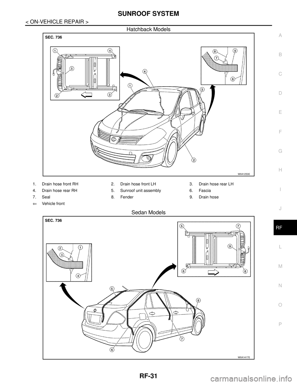
Hatchback Models
Sedan Models
WIIA1253E
1. Drain hose front RH 2. Drain hose front LH 3. Drain hose rear LH
4. Drain hose rear RH 5. Sunroof unit assembly 6. Fascia
7. Seal 8. Fender 9. Drain hose
⇐Vehicle front
WIIA1417E
Page 4592 of 5883

SB-8
< ON-VEHICLE REPAIR >
REAR SEAT BELT
REAR SEAT BELT
Removal and Installation of Rear Seat BeltINFOID:0000000001366761
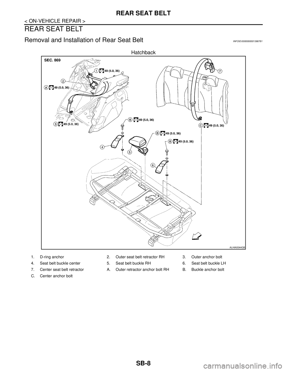
Hatchback
ALHIA0044GB
1. D-ring anchor 2. Outer seat belt retractor RH 3. Outer anchor bolt
4. Seat belt buckle center 5. Seat belt buckle RH 6. Seat belt buckle LH
7. Center seat belt retractor A. Outer retractor anchor bolt RH B. Buckle anchor bolt
C. Center anchor bolt
Page 4593 of 5883

REAR SEAT BELT
SB-9
< ON-VEHICLE REPAIR >
C
D
E
F
G
I
J
K
L
MA
B
SB
N
O
P
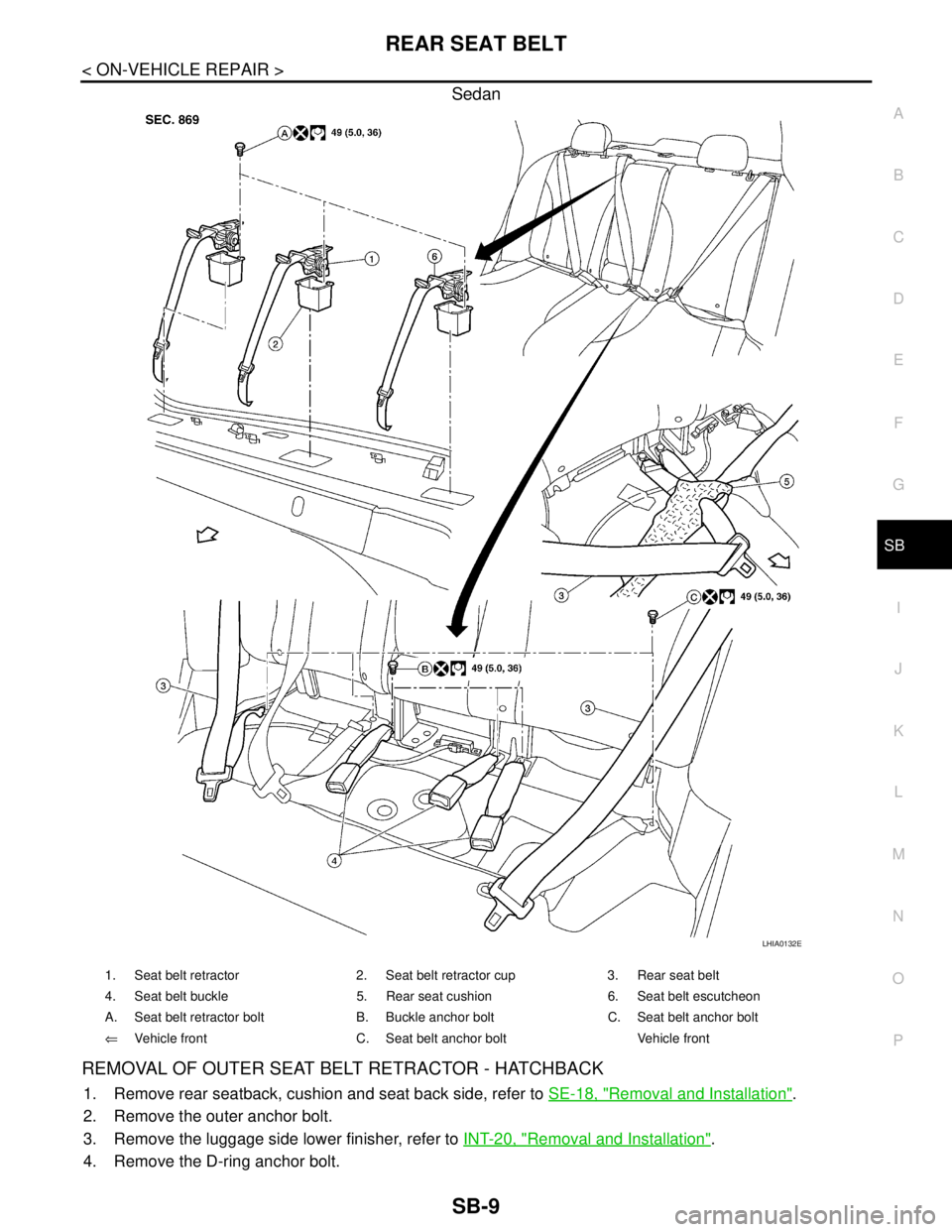
Sedan
REMOVAL OF OUTER SEAT BELT RETRACTOR - HATCHBACK
1. Remove rear seatback, cushion and seat back side, refer to SE-18, "Removal and Installation".
2. Remove the outer anchor bolt.
3. Remove the luggage side lower finisher, refer to INT-20, "
Removal and Installation".
4. Remove the D-ring anchor bolt.
LHIA0132E
1. Seat belt retractor 2. Seat belt retractor cup 3. Rear seat belt
4. Seat belt buckle 5. Rear seat cushion 6. Seat belt escutcheon
A. Seat belt retractor bolt B. Buckle anchor bolt C. Seat belt anchor bolt
⇐Vehicle front C. Seat belt anchor bolt Vehicle front
Page 4594 of 5883

SB-10
< ON-VEHICLE REPAIR >
REAR SEAT BELT
5. Remove the outer retractor anchor bolt, then remove outer seat belt retractor.
INSTALLATION OF OUTER SEAT BELT RETRACTOR - HATCHBACK
Installation is in the reverse order of removal.
REMOVAL OF OUTER SEAT BELT RETRACTOR - SEDAN
1. Remove rear seat cushion, refer to SE-18, "Removal and Installation".
2. Remove outer seat belt anchor bolt.
3. Release the seat belt escutcheon, then remove from belt.
4. Remove rear parcel shelf finisher, refer to INT-26, "
Removal and Installation".
5. Remove outer seat belt retractor bolt, then remove outer seat belt retractor.
INSTALLATION OF OUTER SEAT BELT RETRACTOR - SEDAN
Installation is in the reverse order of removal.
REMOVAL OF CENTER SEAT BELT RETRACTOR - HATCHBACK
1. Remove and disassemble the rear seat cushion, refer to SE-18, "Removal and Installation".
2. Remove the center seat belt retractor.
INSTALLATION OF CENTER SEAT BELT RETRACTOR - HATCHBACK
Installation is in the reverse order of removal.
REMOVAL OF CENTER SEAT BELT RETRACTOR - SEDAN
1. Lift front edge of rear seat cushion and slide forward.
2. Remove center seat belt anchor bolt (A), then pull center seat
belt through rear seat cushion (1).
⇐ Vehicle front
3. Release the seat belt escutcheon, then remove from belt.
4. Remove rear parcel shelf finisher, refer to INT-26, "
Removal and
Installation".
5. Remove the bolt, then remove center seat belt retractor.
INSTALLATION OF CENTER SEAT BELT RETRACTOR - SEDAN
Installation is in the reverse order of removal.
REMOVAL OF SEAT BELT BUCKLE
1. Remove rear seat cushion, refer to SE-18, "Removal and Installation".
2. Remove buckle anchor bolt, then remove seat belt buckle.
INSTALLATION OF SEAT BELT BUCKLE
Installation is in the reverse order of removal.
WIIA1380E
Page 4753 of 5883

SR-10
< ON-VEHICLE REPAIR >
SIDE CURTAIN AIR BAG MODULE
SIDE CURTAIN AIR BAG MODULE
ComponentINFOID:0000000001350507
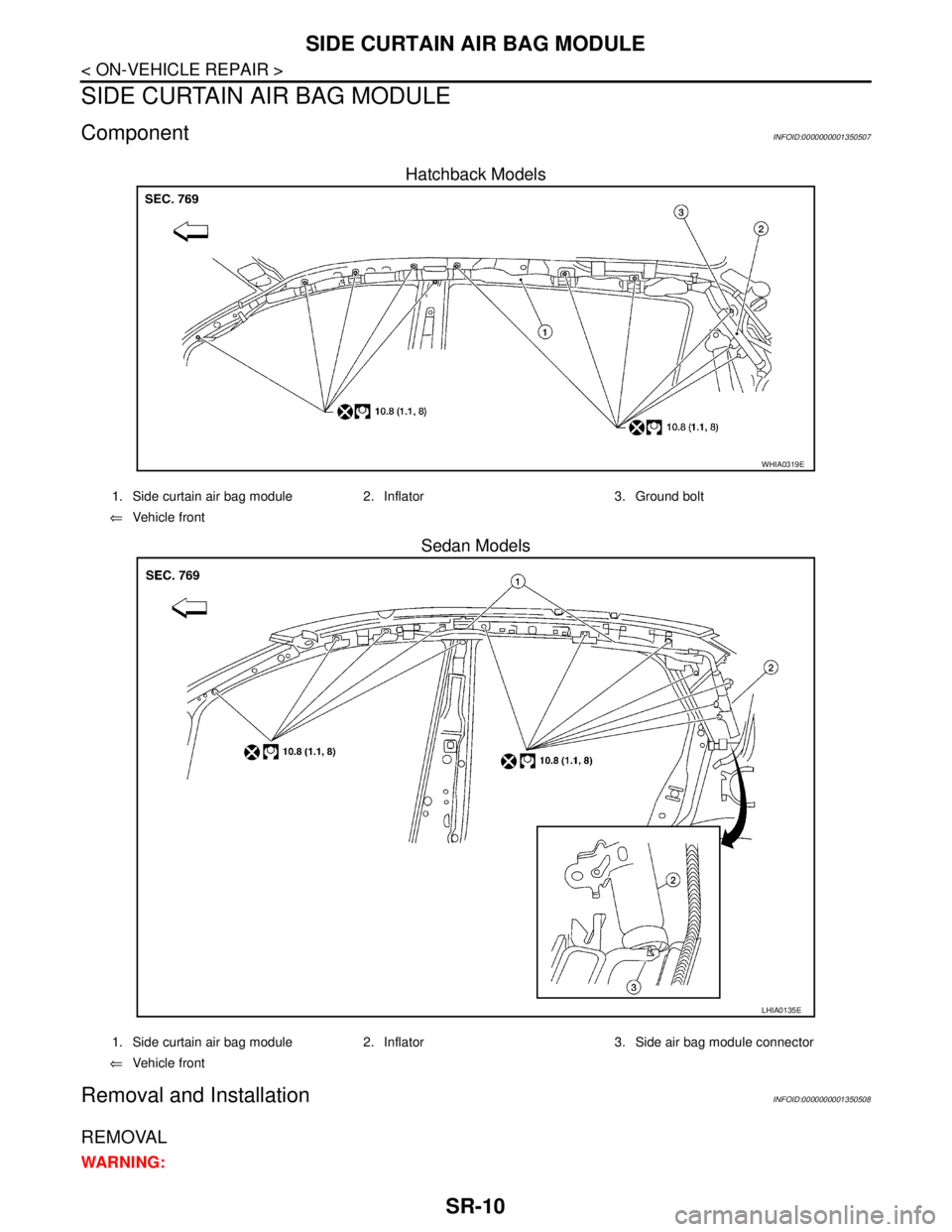
Hatchback Models
Sedan Models
Removal and InstallationINFOID:0000000001350508
REMOVAL
WARNING:
WHIA0319E
1. Side curtain air bag module 2. Inflator 3. Ground bolt
⇐Vehicle front
LHIA0135E
1. Side curtain air bag module 2. Inflator 3. Side air bag module connector
⇐Vehicle front