hatch NISSAN TIIDA 2007 Service Owners Manual
[x] Cancel search | Manufacturer: NISSAN, Model Year: 2007, Model line: TIIDA, Model: NISSAN TIIDA 2007Pages: 5883, PDF Size: 78.95 MB
Page 3269 of 5883
GW-10
< ON-VEHICLE REPAIR >
WINDSHIELD GLASS
ON-VEHICLE REPAIR
WINDSHIELD GLASS
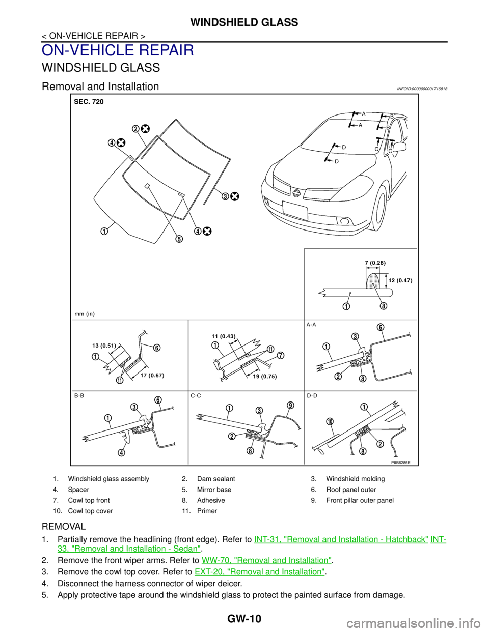
Removal and InstallationINFOID:0000000001716818
REMOVAL
1. Partially remove the headlining (front edge). Refer to INT-31, "Removal and Installation - Hatchback" INT-
33, "Removal and Installation - Sedan".
2. Remove the front wiper arms. Refer to WW-70, "
Removal and Installation".
3. Remove the cowl top cover. Refer to EXT-20, "
Removal and Installation".
4. Disconnect the harness connector of wiper deicer.
5. Apply protective tape around the windshield glass to protect the painted surface from damage.
PIIB6285E
1. Windshield glass assembly 2. Dam sealant 3. Windshield molding
4. Spacer 5. Mirror base 6. Roof panel outer
7. Cowl top front 8. Adhesive 9. Front pillar outer panel
10. Cowl top cover 11. Primer
Page 3277 of 5883
GW-18
< ON-VEHICLE REPAIR >
REAR WINDOW GLASS AND MOLDING
REAR WINDOW GLASS AND MOLDING
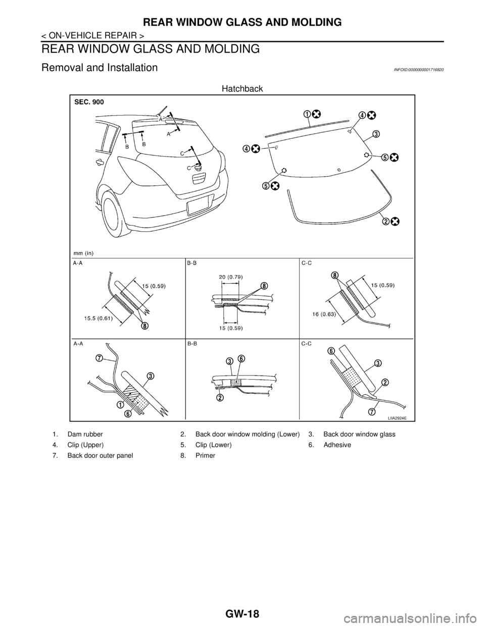
Removal and InstallationINFOID:0000000001716820
Hatchback
LIIA2924E
1. Dam rubber 2. Back door window molding (Lower) 3. Back door window glass
4. Clip (Upper) 5. Clip (Lower) 6. Adhesive
7. Back door outer panel 8. Primer
Page 3657 of 5883
INL-6
< FUNCTION DIAGNOSIS >
INTERIOR ROOM LAMP CONTROL SYSTEM
a signal is received from an Intelligent Key or main power window and door lock/unlock switch, or when the
front door LH lock assembly (key cylinder switch) is locked or unlocked
a door is opened or closed
the Intelligent Key is removed from or inserted into the key slot.
The Interior lamp battery saver control time period can be changed with the function setting of CONSULT-III.
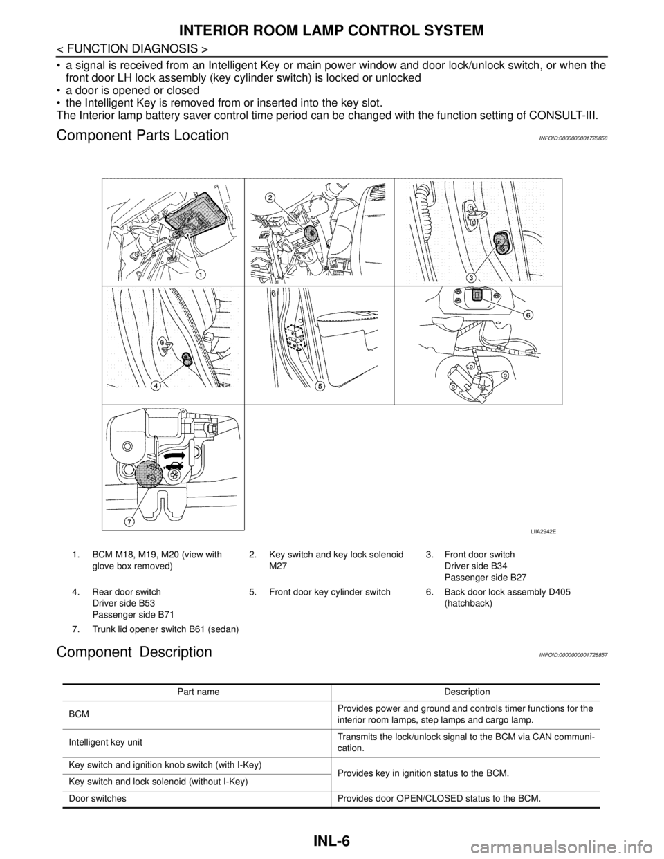
Component Parts LocationINFOID:0000000001728856
Component DescriptionINFOID:0000000001728857
1. BCM M18, M19, M20 (view with
glove box removed)2. Key switch and key lock solenoid
M273. Front door switch
Driver side B34
Passenger side B27
4. Rear door switch
Driver side B53
Passenger side B715. Front door key cylinder switch 6. Back door lock assembly D405
(hatchback)
7. Trunk lid opener switch B61 (sedan)
LIIA2942E
Part name Description
BCMProvides power and ground and controls timer functions for the
interior room lamps, step lamps and cargo lamp.
Intelligent key unitTransmits the lock/unlock signal to the BCM via CAN communi-
cation.
Key switch and ignition knob switch (with I-Key)
Provides key in ignition status to the BCM.
Key switch and lock solenoid (without I-Key)
Door switches Provides door OPEN/CLOSED status to the BCM.
Page 3658 of 5883

INTERIOR ROOM LAMP CONTROL SYSTEM
INL-7
< FUNCTION DIAGNOSIS >
C
D
E
F
G
H
I
J
K
MA
B
INL
N
O
P
Back door lock assembly (hatchback)
Provides back door OPEN/CLOSED status to the BCM.
Back door opener switch (hatchback)
Trunk lid opener switch (sedan) Provides trunk lid OPEN/CLOSED status to the BCM.
Main power window and door lock/unlock switch [front door lock
assembly LH (key cylinder switch)]. Provides door lock/unlock position switch LH status to the BCM.
Page 3677 of 5883
INL-26
< ON-VEHICLE REPAIR >
INTERIOR ROOM LAMP
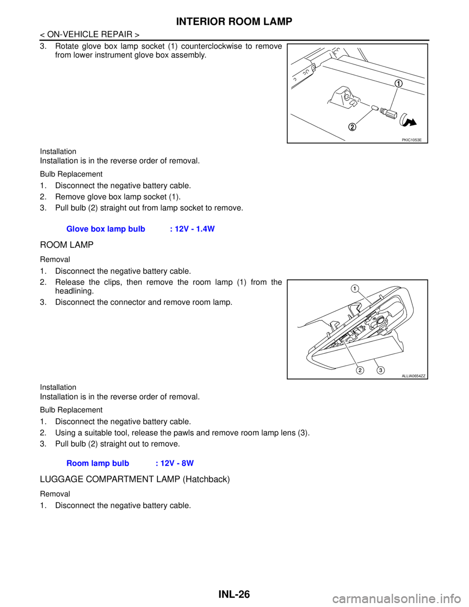
3. Rotate glove box lamp socket (1) counterclockwise to remove
from lower instrument glove box assembly.
Installation
Installation is in the reverse order of removal.
Bulb Replacement
1. Disconnect the negative battery cable.
2. Remove glove box lamp socket (1).
3. Pull bulb (2) straight out from lamp socket to remove.
ROOM LAMP
Removal
1. Disconnect the negative battery cable.
2. Release the clips, then remove the room lamp (1) from the
headlining.
3. Disconnect the connector and remove room lamp.
Installation
Installation is in the reverse order of removal.
Bulb Replacement
1. Disconnect the negative battery cable.
2. Using a suitable tool, release the pawls and remove room lamp lens (3).
3. Pull bulb (2) straight out to remove.
LUGGAGE COMPARTMENT LAMP (Hatchback)
Removal
1. Disconnect the negative battery cable.
PKIC1053E
Glove box lamp bulb : 12V - 1.4W
ALLIA0654ZZ
Room lamp bulb : 12V - 8W
Page 3679 of 5883

INL-28
< SERVICE DATA AND SPECIFICATIONS (SDS)
SERVICE DATA AND SPECIFICATIONS (SDS)
SERVICE DATA AND SPECIFICATIONS (SDS)
SERVICE DATA AND SPECIFICATIONS (SDS)
Bulb SpecificationsINFOID:0000000001726700
* Always check with the Parts Department for the latest parts information.Item Type Wattage (W) Bulb No.*
Map lamp Cylinder 8 AL54
Vanity mirror lamp (if equipped) Cylinder 2 -
Glove box lamp (if equipped) Wedge 1.4 -
Room lamp Cylinder 8 -
Luggage compartment lamp (Hatchback) Cylinder 5 B5Y
Trunk room lamp (Sedan) Wedge 5 158
Page 3680 of 5883

INT-1
BODY INTERIOR
C
D
E
F
G
H
I
K
L
M
SECTION INT
A
B
INT
N
O
P
CONTENTS
INTERIOR
PRECAUTION ...............................................2
PRECAUTIONS ...................................................2
Precaution for Supplemental Restraint System
(SRS) "AIR BAG" and "SEAT BELT PRE-TEN-
SIONER" ...................................................................
2
Precaution .................................................................2
PREPARATION ............................................3
PREPARATION ...................................................3
Commercial Service Tool ..........................................3
CLIP AND FASTENER ........................................4
Description ................................................................4
SQUEAK AND RATTLE TROUBLE DIAGNO-
SIS .......................................................................
7
Work Flow .................................................................7
Generic Squeak and Rattle Troubleshooting ............9
Diagnostic Worksheet .............................................11
ON-VEHICLE REPAIR .................................13
DOOR FINISHER ...............................................13
Removal and Installation .........................................13
TRUNK LID FINISHER ......................................17
Removal and Installation .........................................17
BACK DOOR TRIM ...........................................18
Removal and Installation .........................................18
BODY SIDE TRIM .............................................19
Component ..............................................................19
Removal and Installation .........................................20
LUGGAGE FLOOR TRIM .................................24
Removal and Installation .........................................24
REAR PARCEL SHELF FINISHER ..................26
Removal and Installation .........................................26
FLOOR TRIM ....................................................27
Removal and Installation .........................................27
HEADLINING ....................................................29
Component ..............................................................29
Removal and Installation - Hatchback .....................31
Removal and Installation - Sedan ............................33
TRUNK ROOM TRIM & TRUNK LID FINISH-
ER ......................................................................
35
Removal and Installation .........................................35
Page 3698 of 5883
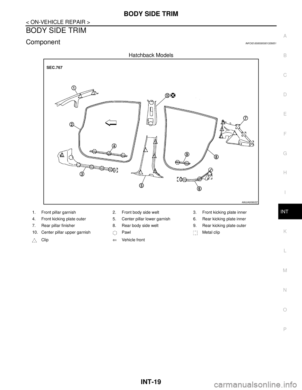
BODY SIDE TRIM
INT-19
< ON-VEHICLE REPAIR >
C
D
E
F
G
H
I
K
L
MA
B
INT
N
O
P
BODY SIDE TRIM
ComponentINFOID:0000000001329051
Hatchback Models
AWJIA0060ZZ
1. Front pillar garnish 2. Front body side welt 3. Front kicking plate inner
4. Front kicking plate outer 5. Center pillar lower garnish 6. Rear kicking plate inner
7. Rear pillar finisher 8. Rear body side welt 9. Rear kicking plate outer
10. Center pillar upper garnish Pawl Metal clip
Clip⇐Vehicle front
Page 3708 of 5883
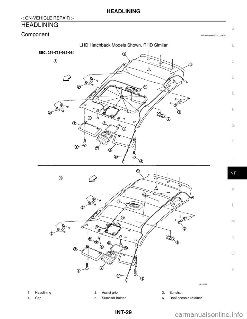
HEADLINING
INT-29
< ON-VEHICLE REPAIR >
C
D
E
F
G
H
I
K
L
MA
B
INT
N
O
P
HEADLINING
ComponentINFOID:0000000001329055
LHD Hatchback Models Shown, RHD Similar
LIIA2576E
1. Headlining 2. Assist grip 3. Sunvisor
4. Cap 5. Sunvisor holder 6. Roof console retainer
Page 3710 of 5883
HEADLINING
INT-31
< ON-VEHICLE REPAIR >
C
D
E
F
G
H
I
K
L
MA
B
INT
N
O
P
Removal and Installation - HatchbackINFOID:0000000001329056
REMOVAL
1. Remove the negative and positive battery cables.
2. Remove front seat assembly RH/LH. Refer to SE-14, "
Removal and Installation".
3. Remove rear seat cushion and rear seatback. Refer to SE-18, "
Removal and Installation".
4. Remove front seat belt shoulder anchor RH/LH. Refer to SB-6, "
Removal and Installation of Front Seat
Belt".
5. Remove center console body assembly. Refer to IP-11, "
Removal and Installation".
6. Remove front pillar garnish RH/LH. Refer to INT-20, "
Removal and Installation".
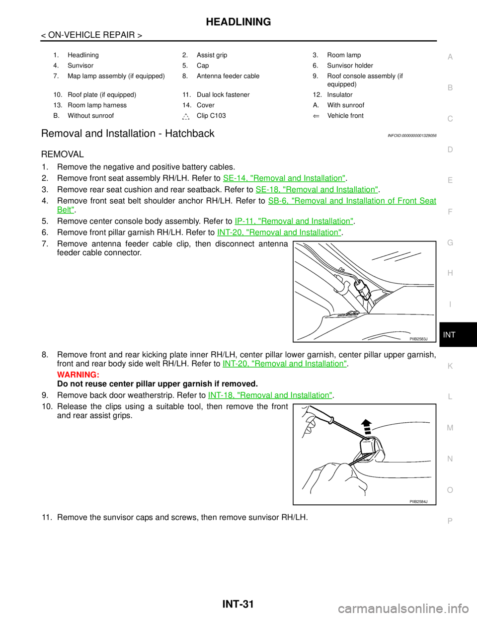
7. Remove antenna feeder cable clip, then disconnect antenna
feeder cable connector.
8. Remove front and rear kicking plate inner RH/LH, center pillar lower garnish, center pillar upper garnish,
front and rear body side welt RH/LH. Refer to INT-20, "
Removal and Installation".
WARNING:
Do not reuse center pillar upper garnish if removed.
9. Remove back door weatherstrip. Refer to INT-18, "
Removal and Installation".
10. Release the clips using a suitable tool, then remove the front
and rear assist grips.
11. Remove the sunvisor caps and screws, then remove sunvisor RH/LH.
1. Headlining 2. Assist grip 3. Room lamp
4. Sunvisor 5. Cap 6. Sunvisor holder
7. Map lamp assembly (if equipped) 8. Antenna feeder cable 9. Roof console assembly (if
equipped)
10. Roof plate (if equipped) 11. Dual lock fastener 12. Insulator
13. Room lamp harness 14. Cover A. With sunroof
B. Without sunroof Clip C103⇐Vehicle front
PIIB2583J
PIIB2584J