brake sensor NISSAN TIIDA 2007 Service User Guide
[x] Cancel search | Manufacturer: NISSAN, Model Year: 2007, Model line: TIIDA, Model: NISSAN TIIDA 2007Pages: 5883, PDF Size: 78.95 MB
Page 254 of 5883
ABS
BRC-21
< FUNCTION DIAGNOSIS >[ABS]
C
D
E
G
H
I
J
K
L
MA
B
BRC
N
O
P
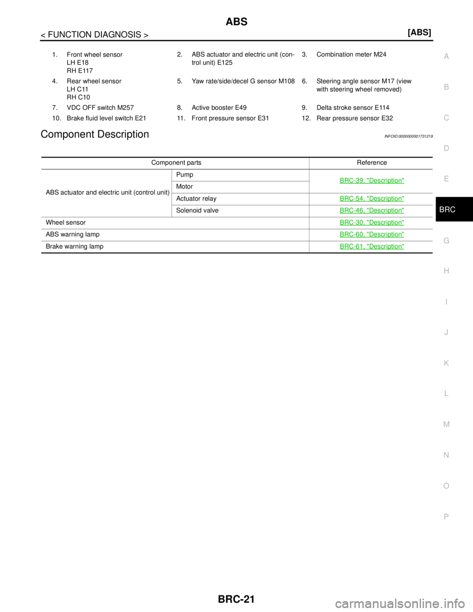
Component DescriptionINFOID:0000000001731219
1. Front wheel sensor
LH E18
RH E1172. ABS actuator and electric unit (con-
trol unit) E1253. Combination meter M24
4. Rear wheel sensor
LH C11
RH C105. Yaw rate/side/decel G sensor M108 6. Steering angle sensor M17 (view
with steering wheel removed)
7. VDC OFF switch M257 8. Active booster E49 9. Delta stroke sensor E114
10. Brake fluid level switch E21 11. Front pressure sensor E31 12. Rear pressure sensor E32
Component parts Reference
ABS actuator and electric unit (control unit)Pump
BRC-39, "
Description"Motor
Actuator relayBRC-54, "
Description"
Solenoid valveBRC-46, "Description"
Wheel sensorBRC-30, "Description"
ABS warning lampBRC-60, "Description"
Brake warning lampBRC-61, "Description"
Page 257 of 5883
BRC-24
< FUNCTION DIAGNOSIS >[ABS]
EBD
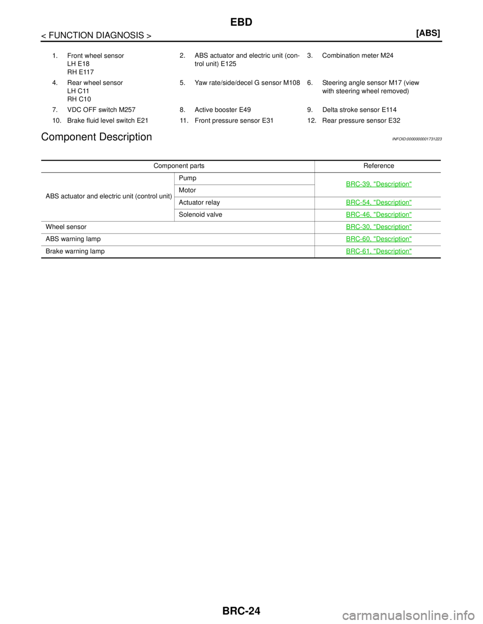
Component Description
INFOID:0000000001731223
1. Front wheel sensor
LH E18
RH E1172. ABS actuator and electric unit (con-
trol unit) E1253. Combination meter M24
4. Rear wheel sensor
LH C11
RH C105. Yaw rate/side/decel G sensor M108 6. Steering angle sensor M17 (view
with steering wheel removed)
7. VDC OFF switch M257 8. Active booster E49 9. Delta stroke sensor E114
10. Brake fluid level switch E21 11. Front pressure sensor E31 12. Rear pressure sensor E32
Component parts Reference
ABS actuator and electric unit (control unit)Pump
BRC-39, "
Description"Motor
Actuator relayBRC-54, "
Description"
Solenoid valveBRC-46, "Description"
Wheel sensorBRC-30, "Description"
ABS warning lampBRC-60, "Description"
Brake warning lampBRC-61, "Description"
Page 258 of 5883
DIAGNOSIS SYSTEM [ABS ACTUATOR AND ELECTRIC UNIT (CONTROL
UNIT)]
BRC-25
< FUNCTION DIAGNOSIS >[ABS]
C
D
E
G
H
I
J
K
L
MA
B
BRC
N
O
P
DIAGNOSIS SYSTEM [ABS ACTUATOR AND ELECTRIC UNIT (CONTROL
UNIT)]
CONSULT-III Function (ABS)INFOID:0000000001731224
FUNCTION
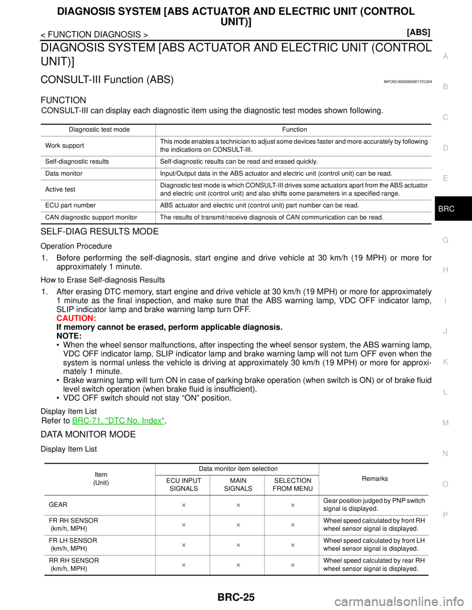
CONSULT-III can display each diagnostic item using the diagnostic test modes shown following.
SELF-DIAG RESULTS MODE
Operation Procedure
1. Before performing the self-diagnosis, start engine and drive vehicle at 30 km/h (19 MPH) or more for
approximately 1 minute.
How to Erase Self-diagnosis Results
1. After erasing DTC memory, start engine and drive vehicle at 30 km/h (19 MPH) or more for approximately
1 minute as the final inspection, and make sure that the ABS warning lamp, VDC OFF indicator lamp,
SLIP indicator lamp and brake warning lamp turn OFF.
CAUTION:
If memory cannot be erased, perform applicable diagnosis.
NOTE:
When the wheel sensor malfunctions, after inspecting the wheel sensor system, the ABS warning lamp,
VDC OFF indicator lamp, SLIP indicator lamp and brake warning lamp will not turn OFF even when the
system is normal unless the vehicle is driving at approximately 30 km/h (19 MPH) or more for approxi-
mately 1 minute.
Brake warning lamp will turn ON in case of parking brake operation (when switch is ON) or of brake fluid
level switch operation (when brake fluid is insufficient).
VDC OFF switch should not stay “ON” position.
Display Item List
Refer to BRC-71, "DTC No. Index".
DATA MONITOR MODE
Display Item List
Diagnostic test mode Function
Work supportThis mode enables a technician to adjust some devices faster and more accurately by following
the indications on CONSULT-III.
Self-diagnostic results Self-diagnostic results can be read and erased quickly.
Data monitor Input/Output data in the ABS actuator and electric unit (control unit) can be read.
Active testDiagnostic test mode is which CONSULT-III drives some actuators apart from the ABS actuator
and electric unit (control unit) and also shifts some parameters in a specified range.
ECU part number ABS actuator and electric unit (control unit) part number can be read.
CAN diagnostic support monitor The results of transmit/receive diagnosis of CAN communication can be read.
Item
(Unit)Data monitor item selection
Remarks
ECU INPUT
SIGNALSMAIN
SIGNALSSELECTION
FROM MENU
GEAR×××Gear position judged by PNP switch
signal is displayed.
FR RH SENSOR
(km/h, MPH)×××Wheel speed calculated by front RH
wheel sensor signal is displayed.
FR LH SENSOR
(km/h, MPH)×××Wheel speed calculated by front LH
wheel sensor signal is displayed.
RR RH SENSOR
(km/h, MPH)×××Wheel speed calculated by rear RH
wheel sensor signal is displayed.
Page 260 of 5883
DIAGNOSIS SYSTEM [ABS ACTUATOR AND ELECTRIC UNIT (CONTROL
UNIT)]
BRC-27
< FUNCTION DIAGNOSIS >[ABS]
C
D
E
G
H
I
J
K
L
MA
B
BRC
N
O
P
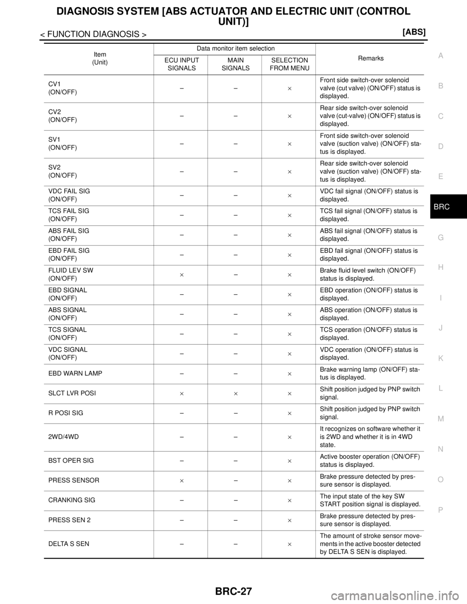
CV1
(ON/OFF)––×Front side switch-over solenoid
valve (cut valve) (ON/OFF) status is
displayed.
CV2
(ON/OFF)––×Rear side switch-over solenoid
valve (cut-valve) (ON/OFF) status is
displayed.
SV1
(ON/OFF)––×Front side switch-over solenoid
valve (suction valve) (ON/OFF) sta-
tus is displayed.
SV2
(ON/OFF)––×Rear side switch-over solenoid
valve (suction valve) (ON/OFF) sta-
tus is displayed.
VDC FAIL SIG
(ON/OFF)––×VDC fail signal (ON/OFF) status is
displayed.
TCS FAIL SIG
(ON/OFF)––×TCS fail signal (ON/OFF) status is
displayed.
ABS FAIL SIG
(ON/OFF)––×ABS fail signal (ON/OFF) status is
displayed.
EBD FAIL SIG
(ON/OFF)––×EBD fail signal (ON/OFF) status is
displayed.
FLUID LEV SW
(ON/OFF)×–×Brake fluid level switch (ON/OFF)
status is displayed.
EBD SIGNAL
(ON/OFF)––×EBD operation (ON/OFF) status is
displayed.
ABS SIGNAL
(ON/OFF)––×ABS operation (ON/OFF) status is
displayed.
TCS SIGNAL
(ON/OFF)––×TCS operation (ON/OFF) status is
displayed.
VDC SIGNAL
(ON/OFF)––×VDC operation (ON/OFF) status is
displayed.
EBD WARN LAMP – –×Brake warning lamp (ON/OFF) sta-
tus is displayed.
SLCT LVR POSI×××Shift position judged by PNP switch
signal.
R POSI SIG – –×Shift position judged by PNP switch
signal.
2WD/4WD – –×It recognizes on software whether it
is 2WD and whether it is in 4WD
state.
BST OPER SIG – –×
Active booster operation (ON/OFF)
status is displayed.
PRESS SENSOR×–×Brake pressure detected by pres-
sure sensor is displayed.
CRANKING SIG – –×The input state of the key SW
START position signal is displayed.
PRESS SEN 2 – –×Brake pressure detected by pres-
sure sensor is displayed.
DELTA S SEN – –×The amount of stroke sensor move-
ments in the active booster detected
by DELTA S SEN is displayed. Item
(Unit)Data monitor item selection
Remarks
ECU INPUT
SIGNALSMAIN
SIGNALSSELECTION
FROM MENU
Page 262 of 5883
DIAGNOSIS SYSTEM [ABS ACTUATOR AND ELECTRIC UNIT (CONTROL
UNIT)]
BRC-29
< FUNCTION DIAGNOSIS >[ABS]
C
D
E
G
H
I
J
K
L
MA
B
BRC
N
O
P
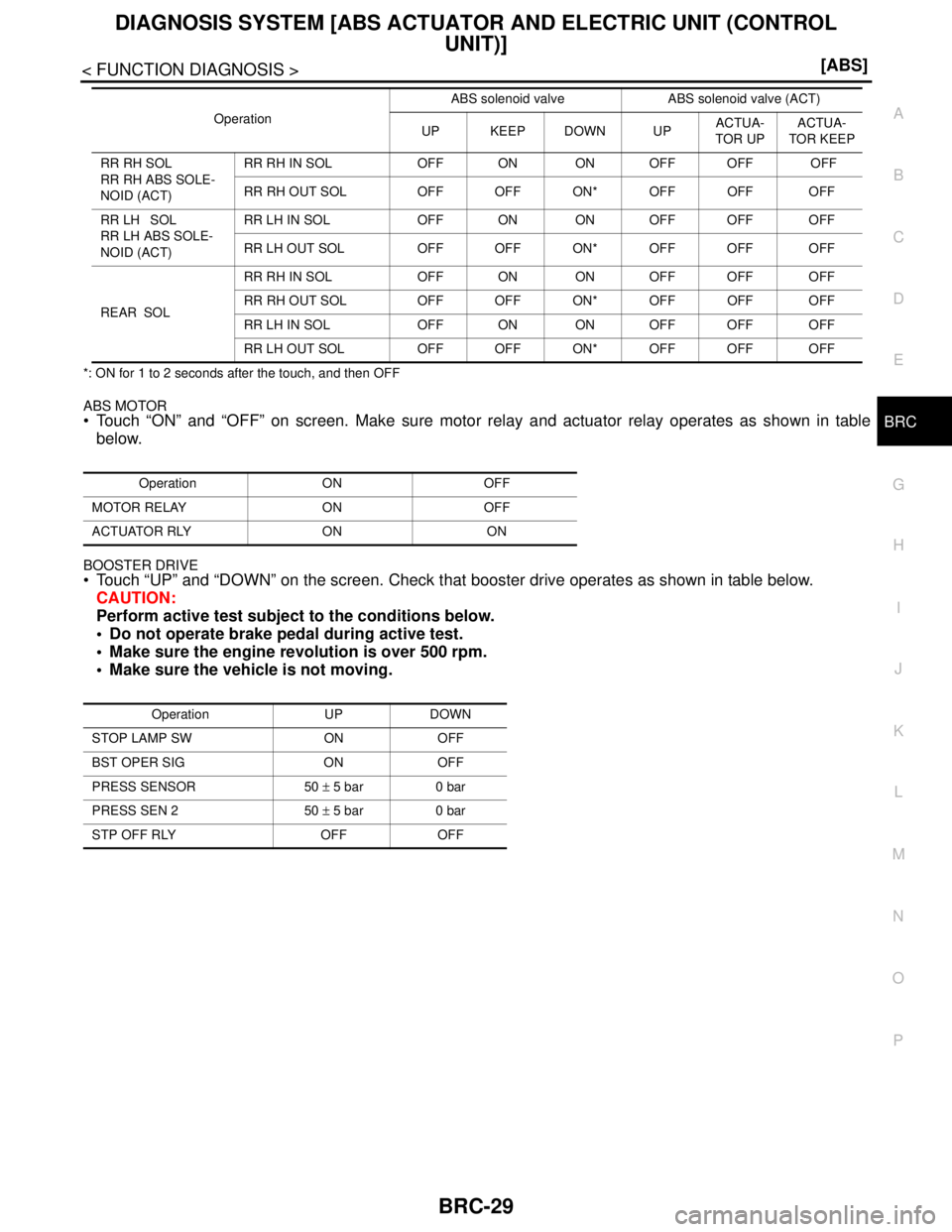
*: ON for 1 to 2 seconds after the touch, and then OFF
ABS MOTOR Touch “ON” and “OFF” on screen. Make sure motor relay and actuator relay operates as shown in table
below.
BOOSTER DRIVE
Touch “UP” and “DOWN” on the screen. Check that booster drive operates as shown in table below.
CAUTION:
Perform active test subject to the conditions below.
Do not operate brake pedal during active test.
Make sure the engine revolution is over 500 rpm.
Make sure the vehicle is not moving.
RR RH SOL
RR RH ABS SOLE-
NOID (ACT)RR RH IN SOL OFF ON ON OFF OFF OFF
RR RH OUT SOL OFF OFF ON* OFF OFF OFF
RR LH SOL
RR LH ABS SOLE-
NOID (ACT)RR LH IN SOL OFF ON ON OFF OFF OFF
RR LH OUT SOL OFF OFF ON* OFF OFF OFF
REAR SOLRR RH IN SOL OFF ON ON OFF OFF OFF
RR RH OUT SOL OFF OFF ON* OFF OFF OFF
RR LH IN SOL OFF ON ON OFF OFF OFF
RR LH OUT SOL OFF OFF ON* OFF OFF OFF
Operation ON OFF
MOTOR RELAY ON OFF
ACTUATOR RLY ON ON
Operation UP DOWN
STOP LAMP SW ON OFF
BST OPER SIG ON OFF
PRESS SENSOR 50 ± 5 bar 0 bar
PRESS SEN 2 50 ± 5 bar 0 bar
STP OFF RLY OFF OFFOperationABS solenoid valve ABS solenoid valve (ACT)
UP KEEP DOWN UPACTUA-
TOR UPACTUA-
TOR KEEP
Page 290 of 5883
C1155 BRAKE FLUID LEVEL SWITCH
BRC-57
< COMPONENT DIAGNOSIS >[ABS]
C
D
E
G
H
I
J
K
L
MA
B
BRC
N
O
P
YES >> GO TO 3
NO >> Repair or replace malfunctioning components.
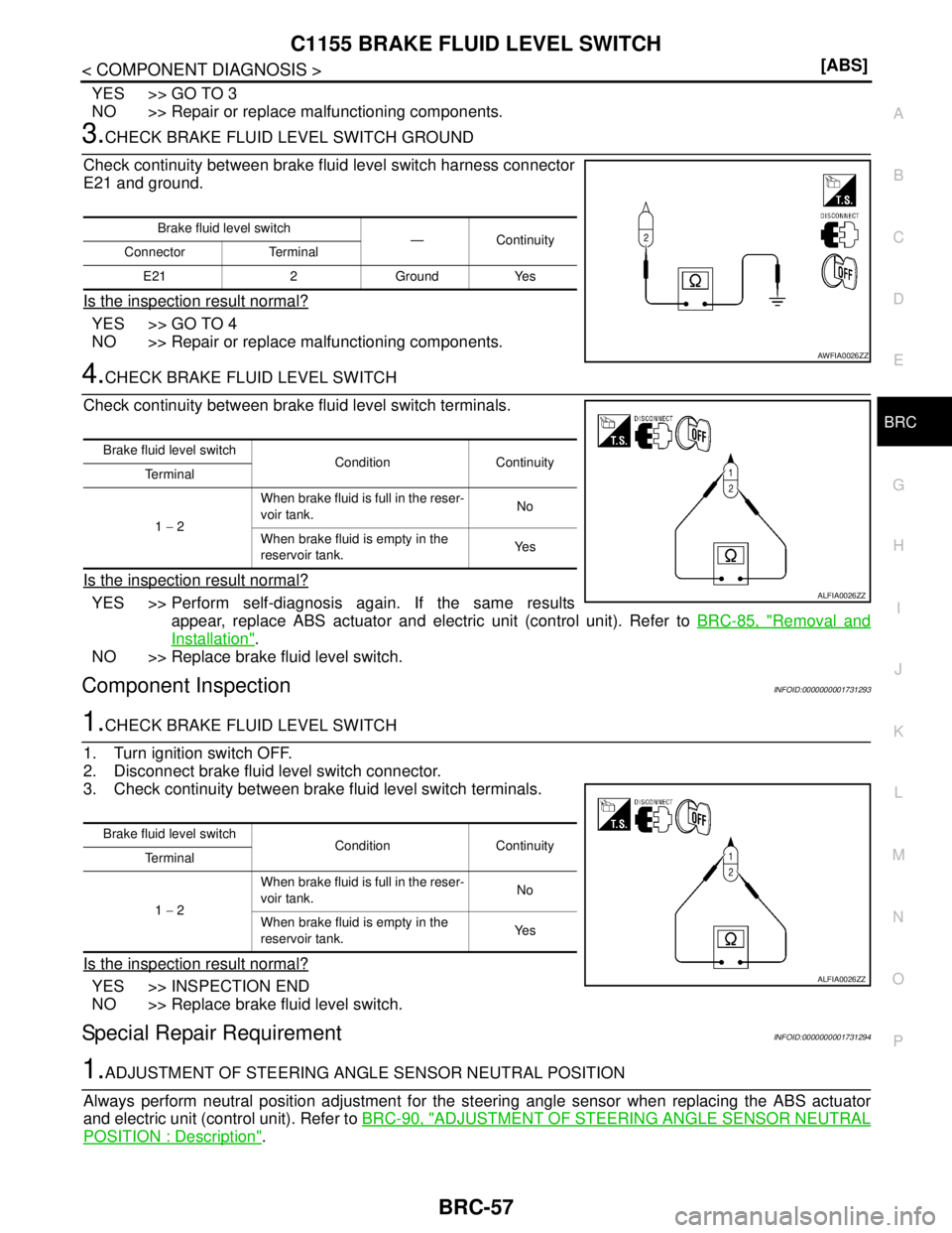
3.CHECK BRAKE FLUID LEVEL SWITCH GROUND
Check continuity between brake fluid level switch harness connector
E21 and ground.
Is the inspection result normal?
YES >> GO TO 4
NO >> Repair or replace malfunctioning components.
4.CHECK BRAKE FLUID LEVEL SWITCH
Check continuity between brake fluid level switch terminals.
Is the inspection result normal?
YES >> Perform self-diagnosis again. If the same results
appear, replace ABS actuator and electric unit (control unit). Refer to BRC-85, "
Removal and
Installation".
NO >> Replace brake fluid level switch.
Component InspectionINFOID:0000000001731293
1.CHECK BRAKE FLUID LEVEL SWITCH
1. Turn ignition switch OFF.
2. Disconnect brake fluid level switch connector.
3. Check continuity between brake fluid level switch terminals.
Is the inspection result normal?
YES >> INSPECTION END
NO >> Replace brake fluid level switch.
Special Repair RequirementINFOID:0000000001731294
1.ADJUSTMENT OF STEERING ANGLE SENSOR NEUTRAL POSITION
Always perform neutral position adjustment for the steering angle sensor when replacing the ABS actuator
and electric unit (control unit). Refer to BRC-90, "
ADJUSTMENT OF STEERING ANGLE SENSOR NEUTRAL
POSITION : Description".
Brake fluid level switch
—Continuity
Connector Terminal
E21 2 Ground Yes
AWFIA0026ZZ
Brake fluid level switch
Condition Continuity
Te r m i n a l
1 − 2When brake fluid is full in the reser-
voir tank.No
When brake fluid is empty in the
reservoir tank.Ye s
ALFIA0026ZZ
Brake fluid level switch
Condition Continuity
Te r m i n a l
1 − 2When brake fluid is full in the reser-
voir tank.No
When brake fluid is empty in the
reservoir tank.Ye s
ALFIA0026ZZ
Page 291 of 5883
BRC-58
< COMPONENT DIAGNOSIS >[ABS]
C1155 BRAKE FLUID LEVEL SWITCH
>> GO TO 2
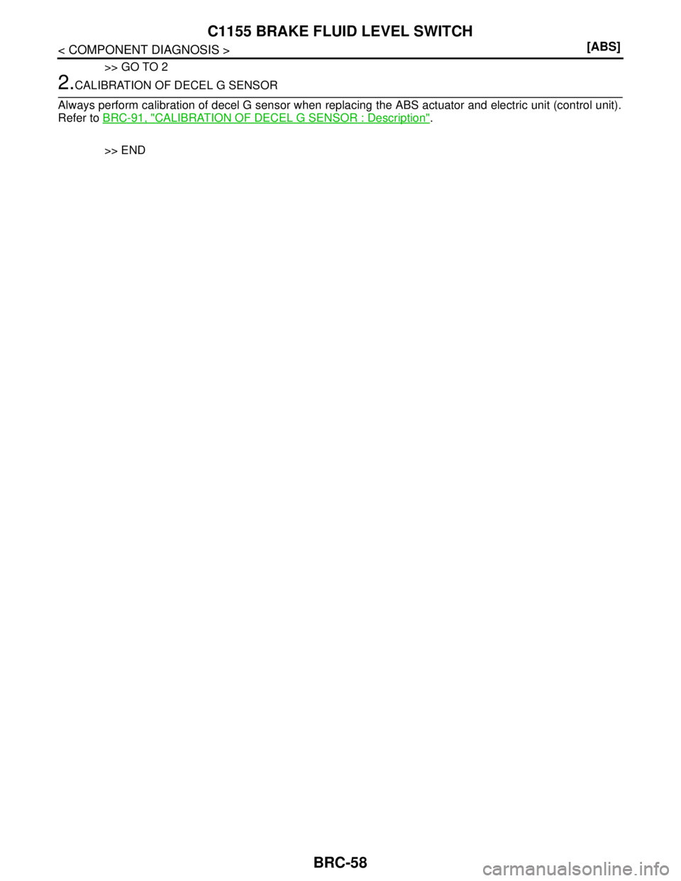
2.CALIBRATION OF DECEL G SENSOR
Always perform calibration of decel G sensor when replacing the ABS actuator and electric unit (control unit).
Refer to BRC-91, "
CALIBRATION OF DECEL G SENSOR : Description".
>> END
Page 295 of 5883
BRC-62
< ECU DIAGNOSIS >[ABS]
ABS ACTUATOR AND ELECTRIC UNIT (CONTROL UNIT)
ECU DIAGNOSIS
ABS ACTUATOR AND ELECTRIC UNIT (CONTROL UNIT)
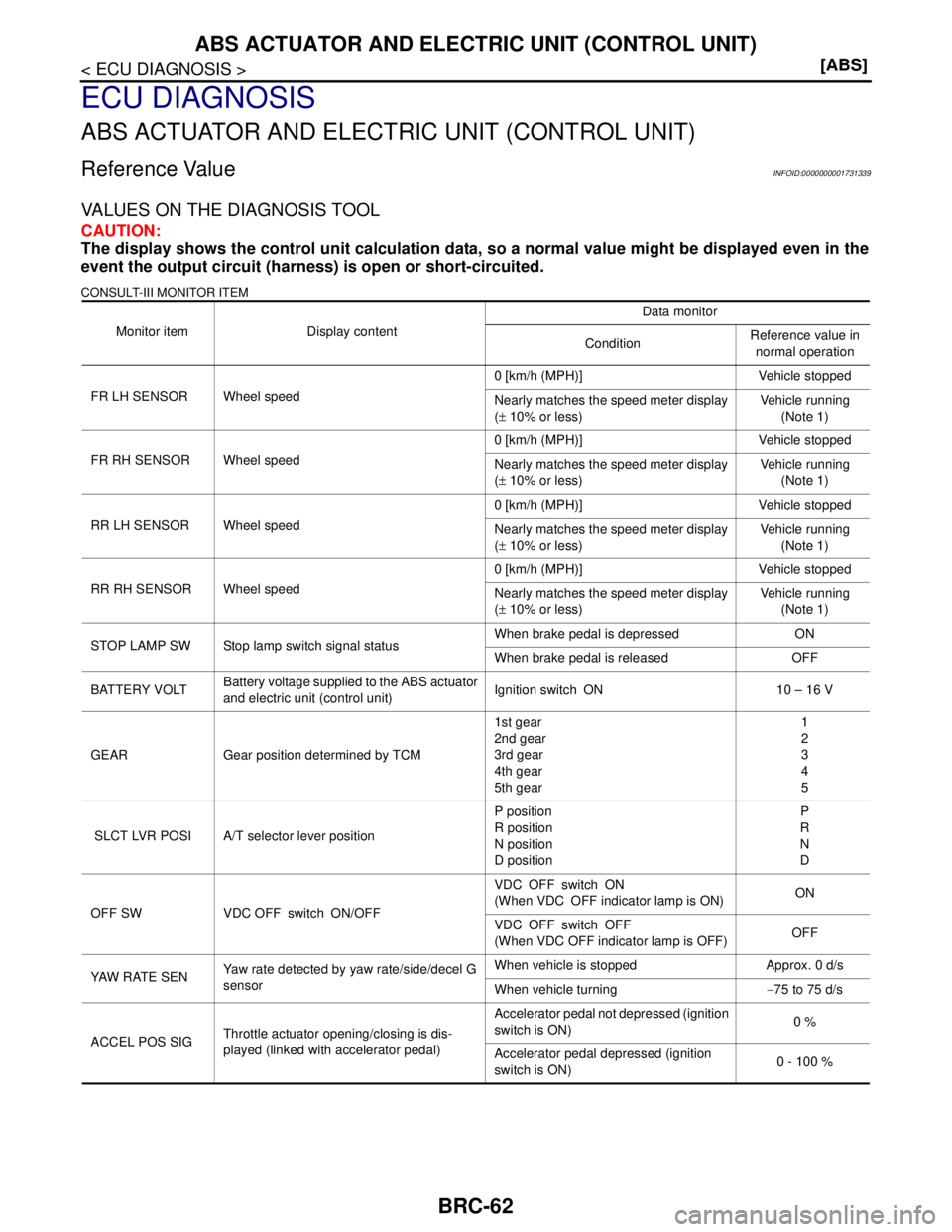
Reference ValueINFOID:0000000001731339
VALUES ON THE DIAGNOSIS TOOL
CAUTION:
The display shows the control unit calculation data, so a normal value might be displayed even in the
event the output circuit (harness) is open or short-circuited.
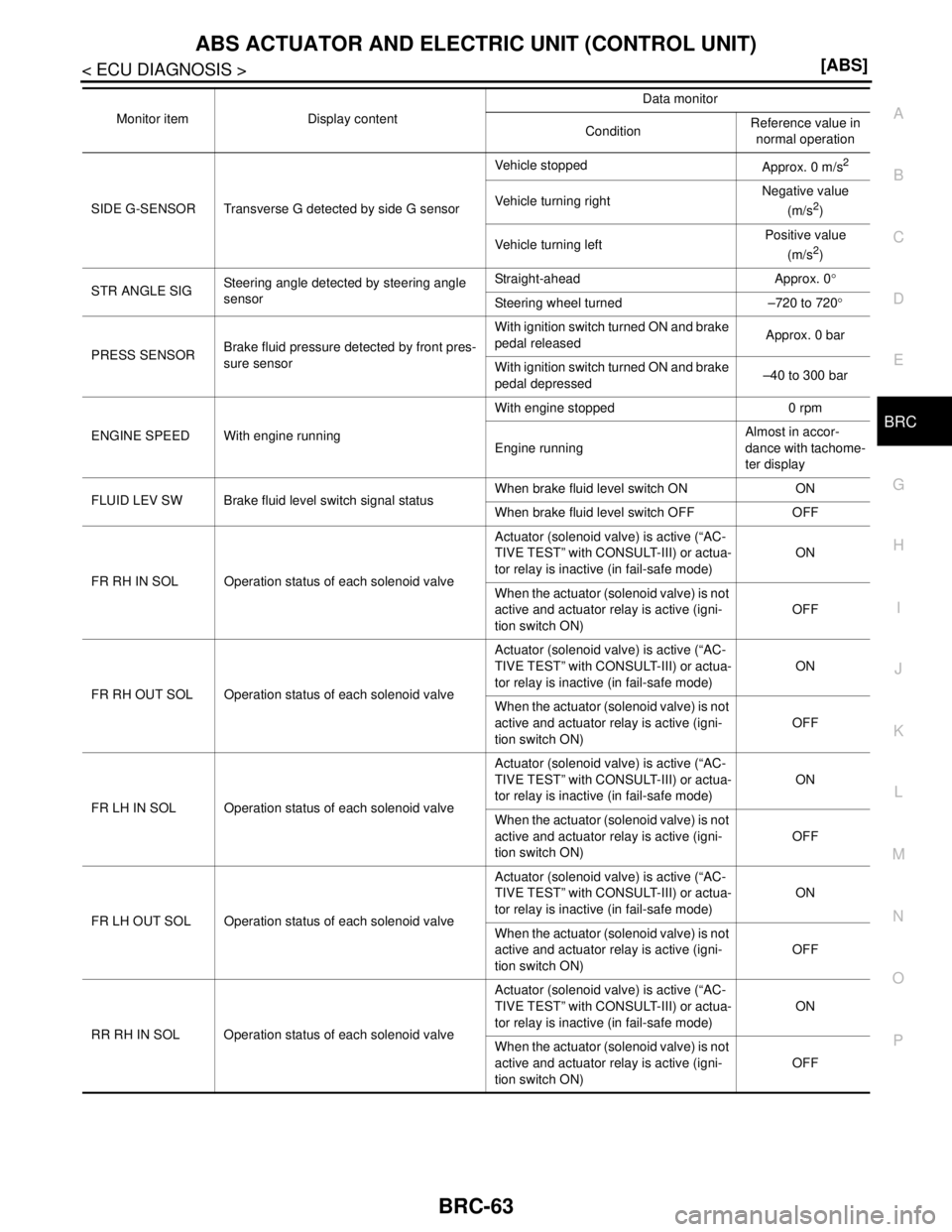
CONSULT-III MONITOR ITEM
Monitor item Display contentData monitor
ConditionReference value in
normal operation
FR LH SENSOR Wheel speed0 [km/h (MPH)] Vehicle stopped
Nearly matches the speed meter display
(± 10% or less)Vehicle running
(Note 1)
FR RH SENSOR Wheel speed0 [km/h (MPH)] Vehicle stopped
Nearly matches the speed meter display
(± 10% or less)Vehicle running
(Note 1)
RR LH SENSOR Wheel speed0 [km/h (MPH)] Vehicle stopped
Nearly matches the speed meter display
(± 10% or less)Vehicle running
(Note 1)
RR RH SENSOR Wheel speed0 [km/h (MPH)] Vehicle stopped
Nearly matches the speed meter display
(± 10% or less)Vehicle running
(Note 1)
STOP LAMP SW Stop lamp switch signal statusWhen brake pedal is depressed ON
When brake pedal is released OFF
BATTERY VOLTBattery voltage supplied to the ABS actuator
and electric unit (control unit)Ignition switch ON 10 – 16 V
GEAR Gear position determined by TCM1st gear
2nd gear
3rd gear
4th gear
5th gear1
2
3
4
5
SLCT LVR POSI A/T selector lever positionP position
R position
N position
D positionP
R
N
D
OFF SW VDC OFF switch ON/OFFVDC OFF switch ON
(When VDC OFF indicator lamp is ON)ON
VDC OFF switch OFF
(When VDC OFF indicator lamp is OFF)OFF
YAW R AT E S E NYaw rate detected by yaw rate/side/decel G
sensorWhen vehicle is stopped Approx. 0 d/s
When vehicle turning−75 to 75 d/s
ACCEL POS SIG Throttle actuator opening/closing is dis-
played (linked with accelerator pedal)Accelerator pedal not depressed (ignition
switch is ON)0 %
Accelerator pedal depressed (ignition
switch is ON)0 - 100 %
Page 296 of 5883
ABS ACTUATOR AND ELECTRIC UNIT (CONTROL UNIT)
BRC-63
< ECU DIAGNOSIS >[ABS]
C
D
E
G
H
I
J
K
L
MA
B
BRC
N
O
P
SIDE G-SENSOR Transverse G detected by side G sensorVehicle stopped
Approx. 0 m/s
2
Vehicle turning rightNegative value
(m/s2)
Vehicle turning leftPositive value
(m/s
2)
STR ANGLE SIGSteering angle detected by steering angle
sensorStraight-ahead Approx. 0°
Steering wheel turned –720 to 720°
PRESS SENSORBrake fluid pressure detected by front pres-
sure sensorWith ignition switch turned ON and brake
pedal releasedApprox. 0 bar
With ignition switch turned ON and brake
pedal depressed–40 to 300 bar
ENGINE SPEED With engine runningWith engine stopped 0 rpm
Engine runningAlmost in accor-
dance with tachome-
ter display
FLUID LEV SW Brake fluid level switch signal statusWhen brake fluid level switch ON ON
When brake fluid level switch OFF OFF
FR RH IN SOL Operation status of each solenoid valve Actuator (solenoid valve) is active (“AC-
TIVE TEST” with CONSULT-III) or actua-
tor relay is inactive (in fail-safe mode)ON
When the actuator (solenoid valve) is not
active and actuator relay is active (igni-
tion switch ON)OFF
FR RH OUT SOL Operation status of each solenoid valve Actuator (solenoid valve) is active (“AC-
TIVE TEST” with CONSULT-III) or actua-
tor relay is inactive (in fail-safe mode)ON
When the actuator (solenoid valve) is not
active and actuator relay is active (igni-
tion switch ON)OFF
FR LH IN SOL Operation status of each solenoid valve Actuator (solenoid valve) is active (“AC-
TIVE TEST” with CONSULT-III) or actua-
tor relay is inactive (in fail-safe mode)ON
When the actuator (solenoid valve) is not
active and actuator relay is active (igni-
tion switch ON)OFF
FR LH OUT SOL Operation status of each solenoid valve Actuator (solenoid valve) is active (“AC-
TIVE TEST” with CONSULT-III) or actua-
tor relay is inactive (in fail-safe mode)ON
When the actuator (solenoid valve) is not
active and actuator relay is active (igni-
tion switch ON)OFF
RR RH IN SOL Operation status of each solenoid valve Actuator (solenoid valve) is active (“AC-
TIVE TEST” with CONSULT-III) or actua-
tor relay is inactive (in fail-safe mode)ON
When the actuator (solenoid valve) is not
active and actuator relay is active (igni-
tion switch ON)OFF Monitor item Display contentData monitor
ConditionReference value in
normal operation
Page 298 of 5883
ABS ACTUATOR AND ELECTRIC UNIT (CONTROL UNIT)
BRC-65
< ECU DIAGNOSIS >[ABS]
C
D
E
G
H
I
J
K
L
MA
B
BRC
N
O
P
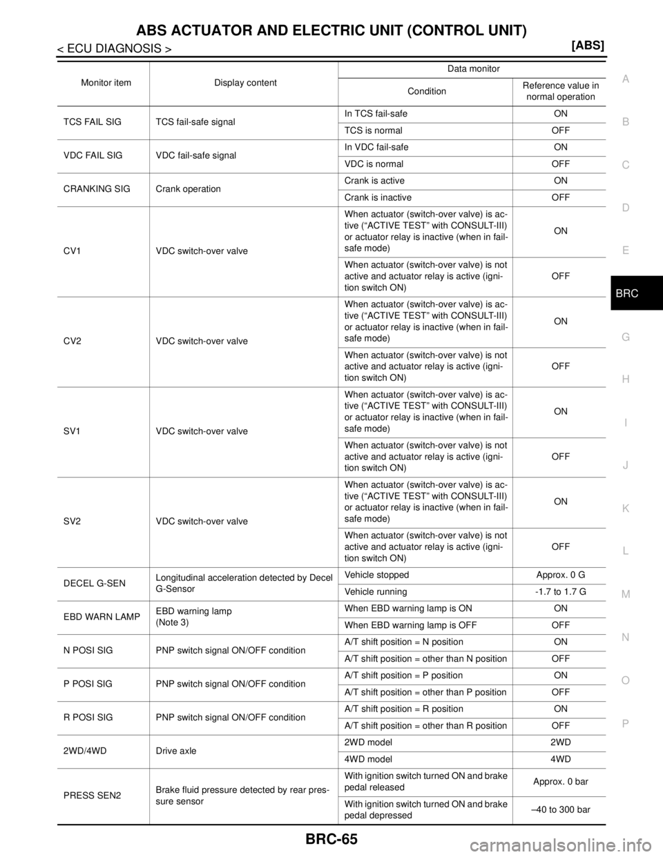
TCS FAIL SIG TCS fail-safe signalIn TCS fail-safe ON
TCS is normal OFF
VDC FAIL SIG VDC fail-safe signalIn VDC fail-safe ON
VDC is normal OFF
CRANKING SIG Crank operationCrank is active ON
Crank is inactive OFF
CV1 VDC switch-over valveWhen actuator (switch-over valve) is ac-
tive (“ACTIVE TEST” with CONSULT-III)
or actuator relay is inactive (when in fail-
safe mode)ON
When actuator (switch-over valve) is not
active and actuator relay is active (igni-
tion switch ON)OFF
CV2 VDC switch-over valveWhen actuator (switch-over valve) is ac-
tive (“ACTIVE TEST” with CONSULT-III)
or actuator relay is inactive (when in fail-
safe mode)ON
When actuator (switch-over valve) is not
active and actuator relay is active (igni-
tion switch ON)OFF
SV1 VDC switch-over valveWhen actuator (switch-over valve) is ac-
tive (“ACTIVE TEST” with CONSULT-III)
or actuator relay is inactive (when in fail-
safe mode)ON
When actuator (switch-over valve) is not
active and actuator relay is active (igni-
tion switch ON)OFF
SV2 VDC switch-over valveWhen actuator (switch-over valve) is ac-
tive (“ACTIVE TEST” with CONSULT-III)
or actuator relay is inactive (when in fail-
safe mode)ON
When actuator (switch-over valve) is not
active and actuator relay is active (igni-
tion switch ON)OFF
DECEL G-SENLongitudinal acceleration detected by Decel
G-SensorVehicle stopped Approx. 0 G
Vehicle running -1.7 to 1.7 G
EBD WARN LAMPEBD warning lamp
(Note 3)When EBD warning lamp is ON ON
When EBD warning lamp is OFF OFF
N POSI SIG PNP switch signal ON/OFF conditionA/T shift position = N position ON
A/T shift position = other than N position OFF
P POSI SIG PNP switch signal ON/OFF conditionA/T shift position = P position ON
A/T shift position = other than P position OFF
R POSI SIG PNP switch signal ON/OFF conditionA/T shift position = R position ON
A/T shift position = other than R position OFF
2WD/4WD Drive axle2WD model 2WD
4WD model 4WD
PRESS SEN2Brake fluid pressure detected by rear pres-
sure sensorWith ignition switch turned ON and brake
pedal releasedApprox. 0 bar
With ignition switch turned ON and brake
pedal depressed–40 to 300 bar Monitor item Display contentData monitor
ConditionReference value in
normal operation