check oil NISSAN TIIDA 2007 Service User Guide
[x] Cancel search | Manufacturer: NISSAN, Model Year: 2007, Model line: TIIDA, Model: NISSAN TIIDA 2007Pages: 5883, PDF Size: 78.95 MB
Page 504 of 5883

THERMOSTAT
CO-23
< ON-VEHICLE REPAIR >[HR16DE]
C
D
E
F
G
H
I
J
K
L
MA
CO
N
P O
Install thermostat (2) into the cylinder block (1) with jiggle valve (A)
facing upwards.
Water Inlet.
After installation, fix water inlet clip (A) on the oil level gauge guide
(1) positioned (b) as shown.
InspectionINFOID:0000000001381573
INSPECTION AFTER REMOVAL
WARNING:
Use a protector to prevent a burn during the work.
Thermostat
Place a thread (A) so that it is caught in the valves of thermostat
(1). Immerse fully in a container (B) filled with water. Heat while
stirring.
The valve opening temperature is the temperature at which the
valve opens and falls from the thread.
Continue heating. Check the full open valve lift amount.
After checking the maximum valve lift amount, lower the water
temperature and check the valve closing temperature.
If out of the standard, replace thermostat.
INSPECTION AFTER INSTALLATION
Check that the reservoir tank cap is tightened.
Check for leaks of engine coolant using suitable tools. Refer to CO-11, "
Inspection".
Start and warm up the engine. Visually make sure that there is no leaks of engine coolant.
PBIC3812E
PBIC3755E
Standard : Refer to CO-27, "Thermostat".
PBIC3314J
Page 519 of 5883

CO-38
< ON-VEHICLE MAINTENANCE >[MR18DE]
RADIATOR
RADIATOR
Checking Radiator CapINFOID:0000000001337842
Check valve seat of radiator cap.
- Check if valve seat is swollen to the extent that the edge of the
plunger cannot be seen when watching it vertically from the top.
- Check if valve seat has no soil and damage.
Pull negative-pressure valve to open it, and make sure that it is
completely closed when released.
- Make sure that there is no dirt or damage on the valve seat of radi-
ator cap negative-pressure valve.
- Make sure that the valve operates properly in the opening and
closing conditions.
Check radiator cap relief pressure using suitable tool.
- When connecting the radiator cap to the tester, apply water or
coolant to the cap seal surface.
- Replace the radiator cap if there is an abnormality in the negative-
pressure valve, or if the open-valve pressure is outside of the stan-
dard values.
Replace radiator cap if there it does not comply to specifications to the above three checks.
CAUTION:
When installing radiator cap, thoroughly wipe out the radiator filler neck to remove any waxy residue
or foreign material.
Checking RadiatorINFOID:0000000001337843
Check radiator for mud or clogging. If necessary, clean radiator as follows.
Be careful not to bend or damage radiator fins.
When radiator is cleaned without removal, remove all surrounding parts such as cooling fan, radiator shroud
and horns. Then tape harness and connectors to prevent water from entering.
1. Apply water by hose to the back side of the radiator core vertically downward.
2. Apply water again to all radiator core surface once per minute.
3. Stop washing if any stains no longer flow out from radiator.
4. Blow air into the back side of radiator core vertically downward.
Use compressed air lower than 490 kPa (4.9 bar, 5 kg/cm
2, 71 psi) and keep distance more than 30 cm
(11.8 in).
PBIC2816E
SMA967B
Standard: 78 – 98 kPa (0.78 - 0.98 bar, 0.8 – 1.0 kg/cm2, 11
– 14 psi)
Limit: 59 kPa (0.59 bar, 0.6 kg/cm
2, 9 psi)
WBIA0570E
Page 526 of 5883

THERMOSTAT
CO-45
< ON-VEHICLE REPAIR >[MR18DE]
C
D
E
F
G
H
I
J
K
L
MA
CO
N
P O
THERMOSTAT
ComponentINFOID:0000000001337850
Removal and InstallationINFOID:0000000001337851
REMOVAL
1. Drain engine coolant. Refer to CO-35, "Changing Engine Coolant".
2. Remove water inlet.
3. Remove thermostat.
4. Remove water pump. Refer to CO-44, "
Removal and Installation".
5. Remove thermostat housing.
INSPECTION AFTER REMOVAL
Place a thread (A) so that it is caught in the valves of thermostat
(1). Immerse fully in a container (B) filled with water. Heat while
stirring.
The valve opening temperature is the temperature at which the
valve opens and falls from the thread.
Continue heating. Check the full open valve lift amount.
After checking the maximum valve lift amount, lower the water
temperature and check the valve closing temperature.
1. Thermostat housing 2. Water hose 3. Radiator hose (lower)
4. Water inlet 5. Thermostat 6. Rubber ring
7. Gasket A. To oil cooler B. To radiator
Engine front
PBIC4485E
PBIC3314J
Page 541 of 5883

CO-60
< ON-VEHICLE MAINTENANCE >[K9K]
RADIATOR
RADIATOR
Checking Radiator CapINFOID:0000000001538671
Check valve seat of radiator cap.
- Check if valve seat is swollen to the extent that the edge of the
plunger cannot be seen when watching it vertically from the top.
- Check if valve seat has no soil and damage.
Pull negative-pressure valve to open it, and make sure that it is
completely closed when released.
- Make sure that there is no dirt or damage on the valve seat of radi-
ator cap negative-pressure valve.
- Make sure that the valve operates properly in the opening and
closing conditions.
Check radiator cap relief pressure using suitable tool.
- When connecting the radiator cap to the tester, apply water or
coolant to the cap seal surface.
- Replace the radiator cap if there is an abnormality in the negative-
pressure valve, or if the open-valve pressure is outside of the stan-
dard values.
Replace radiator cap if there it does not comply to specifications to the above three checks.
CAUTION:
When installing radiator cap, thoroughly wipe out the radiator filler neck to remove any waxy residue
or foreign material.
Checking RadiatorINFOID:0000000001538672
Check radiator for mud or clogging. If necessary, clean radiator as follows.
Be careful not to bend or damage radiator fins.
When radiator is cleaned without removal, remove all surrounding parts such as cooling fan, radiator shroud
and horns. Then tape harness and connectors to prevent water from entering.
1. Apply water by hose to the back side of the radiator core vertically downward.
2. Apply water again to all radiator core surface once per minute.
3. Stop washing if any stains no longer flow out from radiator.
4. Blow air into the back side of radiator core vertically downward.
Use compressed air lower than 490 kPa (4.9 bar, 5 kg/cm
2, 71 psi) and keep distance more than 30 cm
(11.8 in).
PBIC2816E
SMA967B
Standard: 78 – 98 kPa (0.78 - 0.98 bar, 0.8 – 1.0 kg/cm2, 11
– 14 psi)
Limit: 59 kPa (0.59 bar, 0.6 kg/cm
2, 9 psi)
WBIA0570E
Page 1354 of 5883
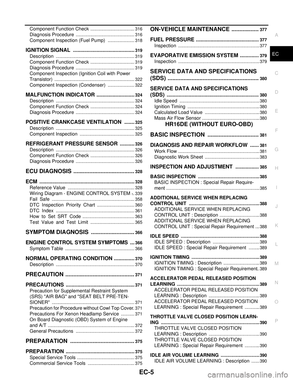
EC-5
C
D
E
F
G
H
I
J
K
L
M
ECA
N
O
P Component Function Check ..................................
316
Diagnosis Procedure .............................................316
Component Inspection (Fuel Pump) .....................318
IGNITION SIGNAL ...........................................319
Description ............................................................319
Component Function Check ..................................319
Diagnosis Procedure .............................................319
Component Inspection (Ignition Coil with Power
Transistor) .............................................................
322
Component Inspection (Condenser) .....................322
MALFUNCTION INDICATOR ...........................324
Description ............................................................324
Component Function Check ..................................324
Diagnosis Procedure .............................................324
POSITIVE CRANKCASE VENTILATION ........325
Description ............................................................325
Component Inspection ..........................................325
REFRIGERANT PRESSURE SENSOR ...........326
Description ............................................................326
Component Function Check ..................................326
Diagnosis Procedure .............................................326
ECU DIAGNOSIS .......................................328
ECM ..................................................................328
Reference Value ...................................................328
Wiring Diagram - ENGINE CONTROL SYSTEM - ..339
Fail Safe ...............................................................358
DTC Inspection Priority Chart .............................360
DTC Index ............................................................361
How to Set SRT Code ........................................363
Test Value and Test Limit ..................................365
SYMPTOM DIAGNOSIS ............................366
ENGINE CONTROL SYSTEM SYMPTOMS ....366
Symptom Table .....................................................366
NORMAL OPERATING CONDITION ...............370
Description ............................................................370
PRECAUTION ............................................371
PRECAUTIONS ................................................371
Precaution for Supplemental Restraint System
(SRS) "AIR BAG" and "SEAT BELT PRE-TEN-
SIONER" ...............................................................
371
Precaution for Procedure without Cowl Top Cover ..371
Precautions For Xenon Headlamp Service ...........371
On Board Diagnostic (OBD) System of Engine
and A/T ..................................................................
372
General Precautions .............................................372
PREPARATION .........................................375
PREPARATION ................................................375
Special Service Tools ............................................375
Commercial Service Tools ....................................375
ON-VEHICLE MAINTENANCE ..................377
FUEL PRESSURE ...........................................377
Inspection ..............................................................377
EVAPORATIVE EMISSION SYSTEM .............379
Inspection ..............................................................379
SERVICE DATA AND SPECIFICATIONS
(SDS) ..........................................................
380
SERVICE DATA AND SPECIFICATIONS
(SDS) ...............................................................
380
Idle Speed .............................................................380
Ignition Timing .......................................................380
Calculated Load Value ..........................................380
Mass Air Flow Sensor ............................................380
HR16DE (WITHOUT EURO-OBD)
BASIC INSPECTION .................................
381
DIAGNOSIS AND REPAIR WORKFLOW ......381
Work Flow ..............................................................381
Diagnostic Work Sheet ..........................................383
INSPECTION AND ADJUSTMENT ................385
BASIC INSPECTION ...............................................385
BASIC INSPECTION : Special Repair Require-
ment .......................................................................
385
ADDITIONAL SERVICE WHEN REPLACING
CONTROL UNIT ......................................................
388
ADDITIONAL SERVICE WHEN REPLACING
CONTROL UNIT : Description ...............................
388
ADDITIONAL SERVICE WHEN REPLACING
CONTROL UNIT : Special Repair Requirement ....
388
IDLE SPEED ............................................................388
IDLE SPEED : Description ....................................389
IDLE SPEED : Special Repair Requirement .........389
IGNITION TIMING ....................................................389
IGNITION TIMING : Description ............................389
IGNITION TIMING : Special Repair Requirement ..389
ACCELERATOR PEDAL RELEASED POSITION
LEARNING ...............................................................
389
ACCELERATOR PEDAL RELEASED POSITION
LEARNING : Description .......................................
389
ACCELERATOR PEDAL RELEASED POSITION
LEARNING : Special Repair Requirement ............
389
THROTTLE VALVE CLOSED POSITION LEARN-
ING ...........................................................................
390
THROTTLE VALVE CLOSED POSITION
LEARNING : Description .......................................
390
THROTTLE VALVE CLOSED POSITION
LEARNING : Special Repair Requirement ............
390
IDLE AIR VOLUME LEARNING ..............................390
IDLE AIR VOLUME LEARNING : Description .......390
Page 1357 of 5883

EC-8
Diagnosis Procedure .............................................564
P1706 PNP SWITCH .......................................566
Description .............................................................566
DTC Logic ..............................................................566
Component Function Check ..................................567
Diagnosis Procedure .............................................567
P1805 BRAKE SWITCH ..................................569
Description .............................................................569
DTC Logic ..............................................................569
Diagnosis Procedure .............................................569
Component Inspection (Stop Lamp Switch) ..........570
P2122, P2123 APP SENSOR ..........................572
Description .............................................................572
DTC Logic ..............................................................572
Diagnosis Procedure .............................................572
Component Inspection ...........................................574
Special Repair Requirement ..................................574
P2127, P2128 APP SENSOR ..........................576
Description .............................................................576
DTC Logic ..............................................................576
Diagnosis Procedure .............................................576
Component Inspection ...........................................579
Special Repair Requirement ..................................579
P2135 TP SENSOR .........................................580
Description .............................................................580
DTC Logic ..............................................................580
Diagnosis Procedure .............................................580
Component Inspection ...........................................582
Special Repair Requirement ..................................582
P2138 APP SENSOR ......................................583
Description .............................................................583
DTC Logic ..............................................................583
Diagnosis Procedure .............................................583
Component Inspection ...........................................586
Special Repair Requirement ..................................586
ASCD BRAKE SWITCH ..................................588
Description .............................................................588
Component Function Check ..................................588
Diagnosis Procedure .............................................588
Component Inspection (ASCD Brake Switch) .......591
Component Inspection (ASCD Clutch Switch) .......591
ASCD INDICATOR ..........................................592
Description .............................................................592
Component Function Check ..................................592
Diagnosis Procedure .............................................592
COOLING FAN ................................................593
Description .............................................................593
Component Function Check ..................................593
Diagnosis Procedure .............................................593
Component Inspection ...........................................595
ELECTRICAL LOAD SIGNAL .........................597
Description ............................................................597
Component Function Check .................................597
Diagnosis Procedure .............................................597
EVAP CANISTER PURGE VOLUME CON-
TROL SOLENOID VALVE ................................
599
Description ............................................................599
Component Function Check .................................599
Diagnosis Procedure .............................................599
Component Inspection ..........................................601
FUEL INJECTOR ..............................................602
Description ............................................................602
Component Function Check .................................602
Diagnosis Procedure .............................................602
Component Inspection ..........................................603
FUEL PUMP .....................................................605
Description ............................................................605
Component Function Check .................................605
Diagnosis Procedure .............................................605
Component Inspection (Fuel Pump) .....................607
HO2S1 ..............................................................608
Description ............................................................608
Component Function Check .................................608
Diagnosis Procedure .............................................609
Component Inspection ..........................................611
HO2S1 HEATER ...............................................613
Description ............................................................613
Component Function Check .................................613
Diagnosis Procedure .............................................613
Component Inspection ..........................................615
HO2S2 ..............................................................616
Description ............................................................616
Component Function Check .................................616
Diagnosis Procedure .............................................617
Component Inspection ..........................................618
HO2S2 HEATER ...............................................620
Description ............................................................620
Component Function Check .................................620
Diagnosis Procedure .............................................620
Component Inspection ..........................................622
IAT SENSOR ....................................................623
Description ............................................................623
Component Function Check .................................623
Diagnosis Procedure .............................................623
Component Inspection ..........................................624
IGNITION SIGNAL ............................................625
Description ............................................................625
Component Function Check .................................625
Diagnosis Procedure .............................................625
Component Inspection (Ignition Coil with Power
Transistor) .............................................................
628
Component Inspection (Condenser) .....................628
Page 1362 of 5883
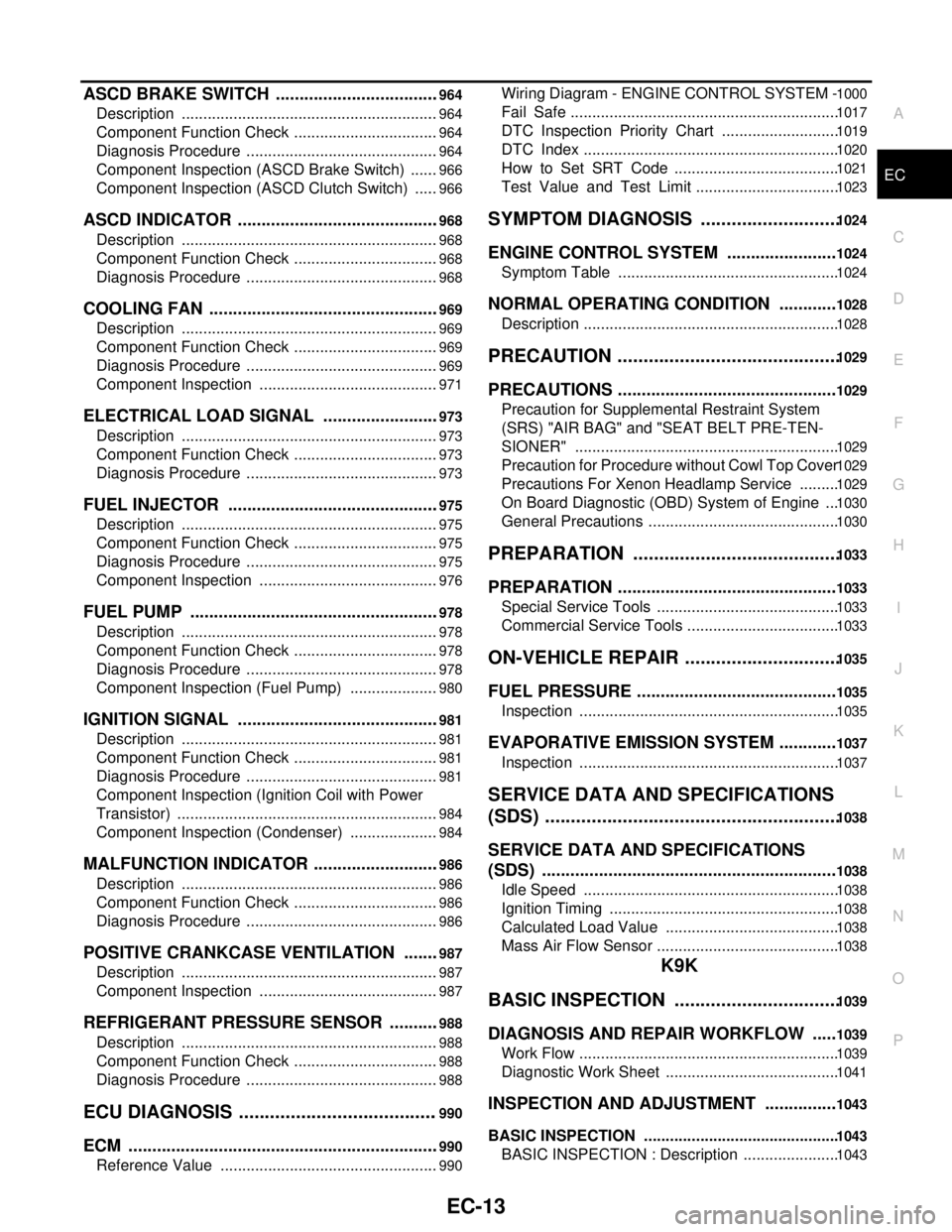
EC-13
C
D
E
F
G
H
I
J
K
L
M
ECA
N
O
P
ASCD BRAKE SWITCH ...................................964
Description ............................................................964
Component Function Check ..................................964
Diagnosis Procedure .............................................964
Component Inspection (ASCD Brake Switch) .......966
Component Inspection (ASCD Clutch Switch) ......966
ASCD INDICATOR ...........................................968
Description ............................................................968
Component Function Check ..................................968
Diagnosis Procedure .............................................968
COOLING FAN .................................................969
Description ............................................................969
Component Function Check ..................................969
Diagnosis Procedure .............................................969
Component Inspection ..........................................971
ELECTRICAL LOAD SIGNAL .........................973
Description ............................................................973
Component Function Check ..................................973
Diagnosis Procedure .............................................973
FUEL INJECTOR .............................................975
Description ............................................................975
Component Function Check ..................................975
Diagnosis Procedure .............................................975
Component Inspection ..........................................976
FUEL PUMP .....................................................978
Description ............................................................978
Component Function Check ..................................978
Diagnosis Procedure .............................................978
Component Inspection (Fuel Pump) .....................980
IGNITION SIGNAL ...........................................981
Description ............................................................981
Component Function Check ..................................981
Diagnosis Procedure .............................................981
Component Inspection (Ignition Coil with Power
Transistor) .............................................................
984
Component Inspection (Condenser) .....................984
MALFUNCTION INDICATOR ...........................986
Description ............................................................986
Component Function Check ..................................986
Diagnosis Procedure .............................................986
POSITIVE CRANKCASE VENTILATION ........987
Description ............................................................987
Component Inspection ..........................................987
REFRIGERANT PRESSURE SENSOR ...........988
Description ............................................................988
Component Function Check ..................................988
Diagnosis Procedure .............................................988
ECU DIAGNOSIS .......................................990
ECM ..................................................................990
Reference Value ...................................................990
Wiring Diagram - ENGINE CONTROL SYSTEM - 1000
Fail Safe ..............................................................1017
DTC Inspection Priority Chart ...........................1019
DTC Index ...........................................................1020
How to Set SRT Code ......................................1021
Test Value and Test Limit .................................1023
SYMPTOM DIAGNOSIS ...........................1024
ENGINE CONTROL SYSTEM .......................1024
Symptom Table ...................................................1024
NORMAL OPERATING CONDITION ............1028
Description ...........................................................1028
PRECAUTION ...........................................1029
PRECAUTIONS ..............................................1029
Precaution for Supplemental Restraint System
(SRS) "AIR BAG" and "SEAT BELT PRE-TEN-
SIONER" .............................................................
1029
Precaution for Procedure without Cowl Top Cover 1029
Precautions For Xenon Headlamp Service .........1029
On Board Diagnostic (OBD) System of Engine ...1030
General Precautions ............................................1030
PREPARATION ........................................1033
PREPARATION ..............................................1033
Special Service Tools ..........................................1033
Commercial Service Tools ...................................1033
ON-VEHICLE REPAIR ..............................1035
FUEL PRESSURE ..........................................1035
Inspection ............................................................1035
EVAPORATIVE EMISSION SYSTEM ............1037
Inspection ............................................................1037
SERVICE DATA AND SPECIFICATIONS
(SDS) .........................................................
1038
SERVICE DATA AND SPECIFICATIONS
(SDS) ..............................................................
1038
Idle Speed ...........................................................1038
Ignition Timing .....................................................1038
Calculated Load Value ........................................1038
Mass Air Flow Sensor ..........................................1038
K9K
BASIC INSPECTION ................................
1039
DIAGNOSIS AND REPAIR WORKFLOW .....1039
Work Flow ............................................................1039
Diagnostic Work Sheet ........................................1041
INSPECTION AND ADJUSTMENT ...............1043
BASIC INSPECTION .............................................1043
BASIC INSPECTION : Description ......................1043
Page 1375 of 5883

EC-26
< BASIC INSPECTION >[HR16DE (WITH EURO-OBD)]
INSPECTION AND ADJUSTMENT
IDLE SPEED : Description
INFOID:0000000001161126
This describes how to check the idle speed. For the actual procedure, follow the instructions in “BASIC
INSPECTION”.
IDLE SPEED : Special Repair RequirementINFOID:0000000001161127
1.CHECK IDLE SPEED
With CONSULT-III
Check idle speed in “DATA MONITOR” mode with CONSULT-III.
With GST
Check idle speed with Service $01 of GST.
>> INSPECTION END
IGNITION TIMING
IGNITION TIMING : DescriptionINFOID:0000000001161128
This describes how to check the ignition timing. For the actual procedure, follow the instructions in “BASIC
INSPECTION”.
IGNITION TIMING : Special Repair RequirementINFOID:0000000001161129
1.CHECK IGNITION TIMING
1. Attach timing light to No.1 ignition coil wire harness (1) as
shown.
2. Check ignition timing.
>> INSPECTION END
ACCELERATOR PEDAL RELEASED POSITION LEARNING
ACCELERATOR PEDAL RELEASED POSITION LEARNING : DescriptionINFOID:0000000001161130
Accelerator Pedal Released Position Learning is a function of ECM to learn the fully released position of the
accelerator pedal by monitoring the accelerator pedal position sensor output signal. It must be performed each
time harness connector of accelerator pedal position sensor or ECM is disconnected.
ACCELERATOR PEDAL RELEASED POSITION LEARNING : Special Repair Re-
2 : Timing light
: Vehicle front
PBIB2955E
1 : Timing indicator
MBIB1331E
Page 1462 of 5883

ON BOARD DIAGNOSTIC (OBD) SYSTEM
EC-113
< FUNCTION DIAGNOSIS >[HR16DE (WITH EURO-OBD)]
C
D
E
F
G
H
I
J
K
L
MA
EC
N
P O
NOTE:
Any monitored item that does not match the vehicle being diagnosed is deleted from the display automatically.
ACTIVE TEST MODE
Test Item
*: Leaving cooling fan OFF with CONSULT-III while engine is running may cause the engine to overheat.
DTC & SRT CONFIRMATION MODE
SRT STATUS Mode
For details, refer to EC-94, "Diagnosis Description".
SRT WORK SUPPORT Mode
AT OD CANCEL ON/OFF Indicates the [ON/OFF] condition of A/T O/D can-
cel to the input signal from the TCM.
CRUISE LAMP ON/OFF Indicates [ON/OFF] condition of CRUISE lamp
determined by the ECM according to the input
signals.
SET LAMP ON/OFF Indicates [ON/OFF] condition of SET lamp deter-
mined by the ECM according to the input signals. Monitored item Unit Description Remarks
TEST ITEM CONDITION JUDGEMENT CHECK ITEM (REMEDY)
FUEL INJECTION Engine: Return to the original
trouble condition
Change the amount of fuel injec-
tion using CONSULT-III.If trouble symptom disappears, see
CHECK ITEM. Harness and connectors
Fuel injector
Heated oxygen sensor 1
IGNITION TIMING Engine: Return to the original
trouble condition
Timing light: Set
Retard the ignition timing using
CONSULT-III.If trouble symptom disappears, see
CHECK ITEM. Perform Idle Air Volume Learn-
ing.
POWER BALANCE Engine: After warming up, idle the
engine.
A/C switch OFF
Shift lever: Neutral
Cut off each fuel injector signal
one at a time using CONSULT-III.Engine runs rough or dies. Harness and connectors
Compression
Fuel injector
Power transistor
Spark plug
Ignition coil
COOLING FAN* Ignition switch: ON
Turn the cooling fan “LOW”, “HI”
and “OFF” CONSULT-III.Cooling fan moves and stops. Harness and connectors
IPDM E/R (Cooling fan relay)
Cooling fan motor
ENG COOLANT
TEMP Engine: Return to the original
trouble condition
Change the engine coolant tem-
perature using CONSULT-III.If trouble symptom disappears, see
CHECK ITEM. Harness and connectors
Engine coolant temperature
sensor
Fuel injector
FUEL PUMP RELAY Ignition switch: ON (Engine
stopped)
Turn the fuel pump relay “ON”
and “OFF” using CONSULT-III
and listen to operating sound.Fuel pump relay makes the operat-
ing sound. Harness and connectors
Fuel pump relay
PURG VOL CONT/V Engine: After warming up, run en-
gine at 1,500 rpm.
Change the EVAP canister purge
volume control solenoid valve
opening percent using CON-
SULT-III.Engine speed changes according
to the opening percent. Harness and connectors
Solenoid valve
V/T ASSIGN ANGLE Engine: Return to the original
trouble condition
Change intake valve timing using
CONSULT-III.If trouble symptom disappears, see
CHECK ITEM. Harness and connectors
Intake valve timing control sole-
noid valve
Page 1468 of 5883

TROUBLE DIAGNOSIS - SPECIFICATION VALUE
EC-119
< COMPONENT DIAGNOSIS >[HR16DE (WITH EURO-OBD)]
C
D
E
F
G
H
I
J
K
L
MA
EC
N
P O
NOTE:
Check “A/F ALPHA-B1” for approximately 1 minute because they may fluctuate. It is NG if the indication is
out of the SP value even a little.
Is the measurement value within the SP value?
YES >> GO TO 17.
NO-1 >> Less than the SP value: GO TO 2.
NO-2 >> More than the SP value: GO TO 3.
2.CHECK “B/FUEL SCHDL”
Select “B/FUEL SCHDL” in “SPEC” of “DATA MONITOR” mode, and make sure that the indication is within the
SP value.
Is the measurement value within the SP value?
YES >> GO TO 4.
NO >> More than the SP value: GO TO 19.
3.CHECK “B/FUEL SCHDL”
Select “B/FUEL SCHDL” in “SPEC” of “DATA MONITOR” mode, and make sure that the indication is within the
SP value.
Is the measurement value within the SP value?
YES >> GO TO 6.
NO-1 >> More than the SP value: GO TO 6.
NO-2 >> Less than the SP value: GO TO 25.
4.CHECK “A/F ALPHA-B1”
1. Stop the engine.
2. Disconnect PCV hose, and then plug it.
3. Start engine.
4. Select “A/F ALPHA-B1” in “SPEC” of “DATA MONITOR” mode, and make sure that the indication is within
the SP value.
Is the measurement value within the SP value?
YES >> GO TO 5.
NO >> GO TO 6.
5.CHANGE ENGINE OIL
1. Stop the engine.
2. Change engine oil.
NOTE:
This symptom may occur when a large amount of gasoline is mixed with engine oil because of driving
conditions (such as when engine oil temperature does not rise enough since a journey distance is too
short during winter). The symptom will not be detected after changing engine oil or changing driving con-
dition.
>>INSPECTION END
6.CHECK FUEL PRESSURE
Check fuel pressure. (Refer to EC-377, "
Inspection".)
Is the inspection result normal?
YES >> GO TO 9.
NO-1 >> Fuel pressure is too high: Replace “fuel filter and fuel pump assembly” and then GO TO 8.
NO-2 >> Fuel pressure is too low: GO TO 7.
7.DETECT MALFUNCTIONING PART
Check fuel hoses and fuel tubes for clogging
Is the inspection result normal?
YES >> Replace “fuel filter and fuel pump assembly” and then GO TO 8.
NO >> Repair or replace and then GO TO 8.
8.CHECK “A/F ALPHA-B1”