sunroof NISSAN TIIDA 2007 Service User Guide
[x] Cancel search | Manufacturer: NISSAN, Model Year: 2007, Model line: TIIDA, Model: NISSAN TIIDA 2007Pages: 5883, PDF Size: 78.95 MB
Page 4535 of 5883

RF-1
BODY EXTERIOR, DOORS, ROOF & VEHICLE SECURITY
C
D
E
F
G
H
I
J
L
M
SECTION RF
A
B
RF
N
O
P
CONTENTS
ROOF
PRECAUTION ...............................................3
PRECAUTIONS ...................................................3
Precaution for Supplemental Restraint System
(SRS) "AIR BAG" and "SEAT BELT PRE-TEN-
SIONER" ...................................................................
3
PREPARATION ............................................4
PREPARATION ...................................................4
Commercial Service Tool ..........................................4
BASIC INSPECTION ....................................5
DIAGNOSIS AND REPAIR WORKFLOW ..........5
Work Flow .................................................................5
INSPECTION AND ADJUSTMENT .....................7
ADDITIONAL SERVICE WHEN REPLACING
CONTROL UNIT ..........................................................
7
ADDITIONAL SERVICE WHEN REPLACING
CONTROL UNIT : Description ..................................
7
ADDITIONAL SERVICE WHEN REPLACING
CONTROL UNIT : Special Repair Requirement .......
7
FUNCTION DIAGNOSIS ...............................8
SUNROOF SYSTEM ...........................................8
System Diagram .......................................................8
System Description ...................................................8
Component Parts Location ......................................9
Component Description ............................................9
DIAGNOSIS SYSTEM (BCM) ............................10
COMMON ITEM .........................................................10
COMMON ITEM : CONSULT-III Function (BCM -
COMMON ITEM) .....................................................
10
RETAINED PWR .......................................................10
RETAINED PWR : CONSULT-III Function (BCM -
RETAINED PWR) ...................................................
10
COMPONENT DIAGNOSIS .........................11
POWER SUPPLY AND GROUND CIRCUIT ....11
SUNROOF MOTOR ASSEMBLY ..............................11
SUNROOF MOTOR ASSEMBLY :
Diagnosis Procedure ..............................................
11
SUNROOF MOTOR ASSEMBLY : Special Repair
Requirement ............................................................
12
SUNROOF SWITCH CIRCUIT ..........................13
Description ...............................................................13
Component Function Check ..................................13
Diagnosis Procedure ...............................................13
DOOR SWITCH .................................................15
Description ...............................................................15
Component Function Check ....................................15
Diagnosis Procedure ...............................................15
ECU DIAGNOSIS .........................................17
BCM (BODY CONTROL MODULE) .................17
Reference Value ......................................................17
SUNROOF SYSTEM .........................................18
Reference Value ......................................................18
Wiring Diagram ........................................................19
SYMPTOM DIAGNOSIS ..............................24
SQUEAK AND RATTLE TROUBLE DIAG-
NOSES ..............................................................
24
Work Flow ................................................................24
Generic Squeak and Rattle Troubleshooting ...........26
Diagnostic Worksheet ..............................................28
ON-VEHICLE REPAIR .................................30
SUNROOF SYSTEM .........................................30
Inspection ................................................................30
Fitting Adjustment ....................................................32
Exploded View .........................................................34
Page 4541 of 5883

INSPECTION AND ADJUSTMENT
RF-7
< BASIC INSPECTION >
C
D
E
F
G
H
I
J
L
MA
B
RF
N
O
P
INSPECTION AND ADJUSTMENT
ADDITIONAL SERVICE WHEN REPLACING CONTROL UNIT
ADDITIONAL SERVICE WHEN REPLACING CONTROL UNIT : Description
INFOID:0000000001724556
MEMORY RESET PROCEDURE
1. Please observe the following instructions while confirming the sunroof operation.
NOTE:
Do not disconnect the battery power while the sunroof is operating or within 5 seconds after the sunroof
stops (to wipe-out the memory of lid position and operating friction).
2. Initialization of system should be conducted after the following conditions.
When the battery has been disconnected or discharged.
When the sunroof motor has been disconnected from power.
When the sunroof motor is changed.
When the sunroof does not operate normally (Incomplete initialization conditions).
ADDITIONAL SERVICE WHEN REPLACING CONTROL UNIT : Special Repair Re-
quirement
INFOID:0000000001724557
INITIALIZATION PROCEDURE
If the sunroof does not close or open automatically, use the following procedure to return sunroof operation to
normal.
1. Turn ignition switch ON.
2. Push and release the tilt up switch to start the tilt up operation.
3. Push and hold the tilt up switch until the sunroof pops up.
NOTE:
The sunroof will move toward the tilt up direction and will be stopped mechanically, at which time it will be
automatically fully closed. Keep pushing the switch during this operation. Release the switch when the
operation is complete.
4. Push and hold the tilt up switch within 10 seconds of step 3.
5. After 4 seconds, the sunroof will be automatically cycled in sequence of slide open-tilt up-tilt down.
NOTE:
Keep pushing the switch during this operation.
6. When the sunroof stops, release the switch 0.5 second later.
7. If the slide switch operates normally, the initialization is complete.
Page 4542 of 5883
RF-8
< FUNCTION DIAGNOSIS >
SUNROOF SYSTEM
FUNCTION DIAGNOSIS
SUNROOF SYSTEM
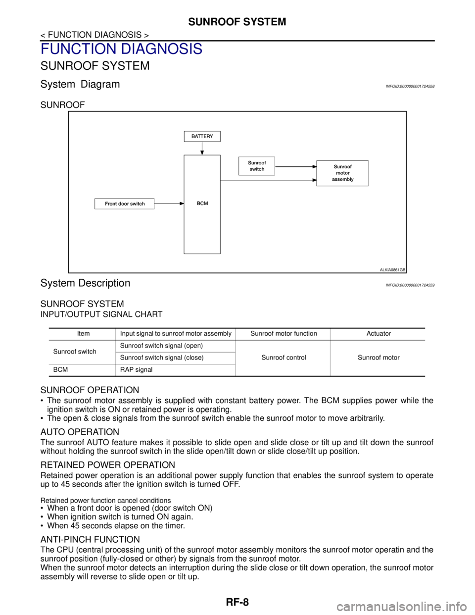
System DiagramINFOID:0000000001724558
SUNROOF
System DescriptionINFOID:0000000001724559
SUNROOF SYSTEM
INPUT/OUTPUT SIGNAL CHART
SUNROOF OPERATION
The sunroof motor assembly is supplied with constant battery power. The BCM supplies power while the
ignition switch is ON or retained power is operating.
The open & close signals from the sunroof switch enable the sunroof motor to move arbitrarily.
AUTO OPERATION
The sunroof AUTO feature makes it possible to slide open and slide close or tilt up and tilt down the sunroof
without holding the sunroof switch in the slide open/tilt down or slide close/tilt up position.
RETAINED POWER OPERATION
Retained power operation is an additional power supply function that enables the sunroof system to operate
up to 45 seconds after the ignition switch is turned OFF.
Retained power function cancel conditions
When a front door is opened (door switch ON)
When ignition switch is turned ON again.
When 45 seconds elapse on the timer.
ANTI-PINCH FUNCTION
The CPU (central processing unit) of the sunroof motor assembly monitors the sunroof motor operatin and the
sunroof position (fully-closed or other) by signals from the sunroof motor.
When the sunroof motor detects an interruption during the slide close or tilt down operation, the sunroof motor
assembly will reverse to slide open or tilt up.
ALKIA0861GB
Item Input signal to sunroof motor assembly Sunroof motor function Actuator
Sunroof switchSunroof switch signal (open)
Sunroof control Sunroof motor Sunroof switch signal (close)
BCM RAP signal
Page 4543 of 5883
SUNROOF SYSTEM
RF-9
< FUNCTION DIAGNOSIS >
C
D
E
F
G
H
I
J
L
MA
B
RF
N
O
P
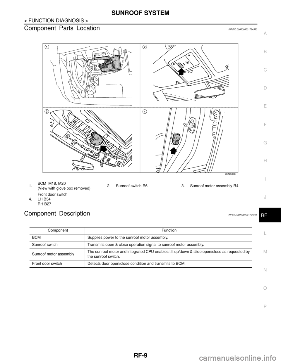
Component Parts LocationINFOID:0000000001724560
Component DescriptionINFOID:0000000001724561
LIIA2597E
1.BCM M18, M20
(View with glove box removed)2. Sunroof switch R6 3. Sunroof motor assembly R4
4.Front door switch
LH B34
RH B27
Component Function
BCM Supplies power to the sunroof motor assembly.
Sunroof switch Transmits open & close operation signal to sunroof motor assembly.
Sunroof motor assemblyThe sunroof motor and integrated CPU enables tilt up/down & slide open/close as requested by
the sunroof switch.
Front door switch Detects door open/close condition and transmits to BCM.
Page 4545 of 5883
POWER SUPPLY AND GROUND CIRCUIT
RF-11
< COMPONENT DIAGNOSIS >
C
D
E
F
G
H
I
J
L
MA
B
RF
N
O
P
COMPONENT DIAGNOSIS
POWER SUPPLY AND GROUND CIRCUIT
SUNROOF MOTOR ASSEMBLY
SUNROOF MOTOR ASSEMBLY : Diagnosis ProcedureINFOID:0000000001724564
SUNROOF MOTOR ASSEMBLY
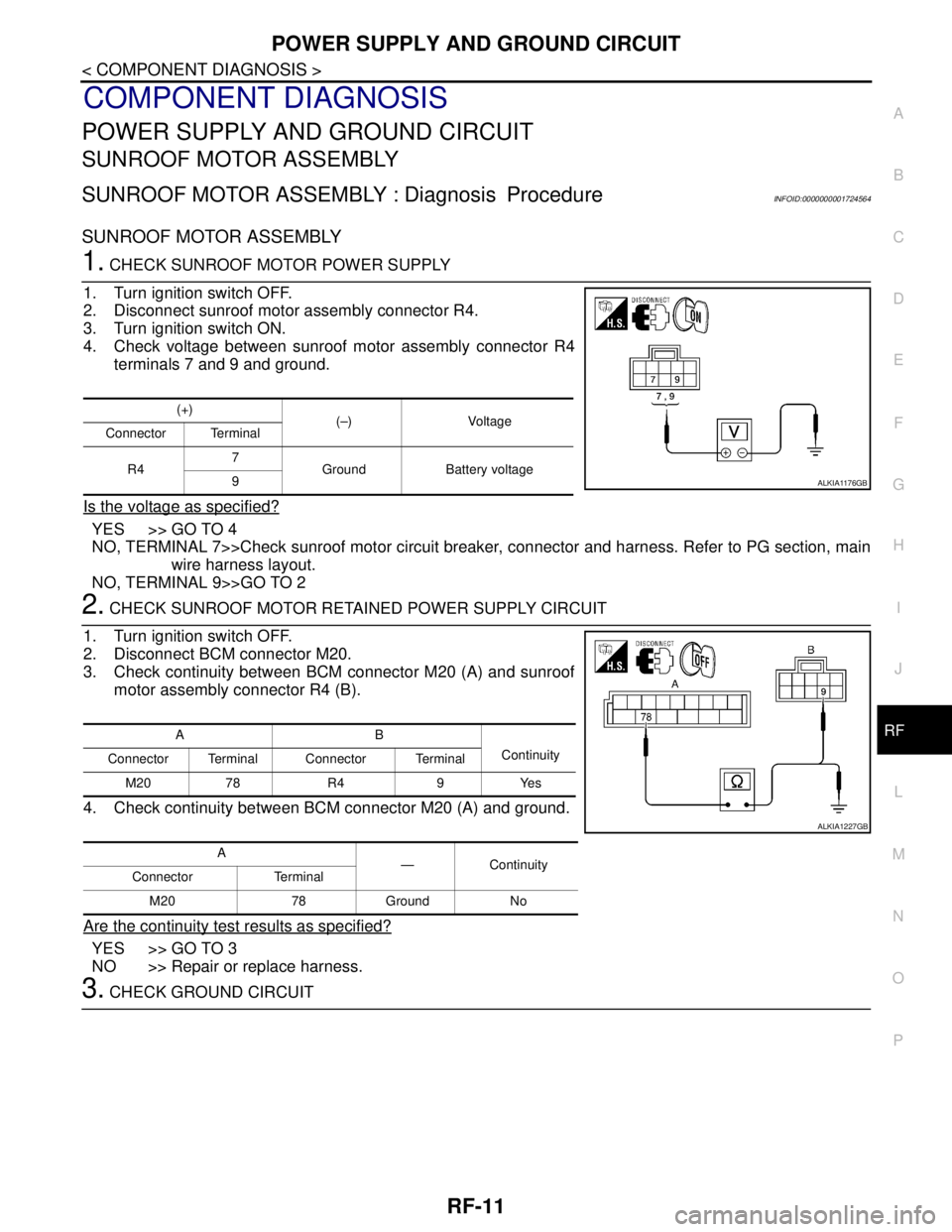
1. CHECK SUNROOF MOTOR POWER SUPPLY
1. Turn ignition switch OFF.
2. Disconnect sunroof motor assembly connector R4.
3. Turn ignition switch ON.
4. Check voltage between sunroof motor assembly connector R4
terminals 7 and 9 and ground.
Is the voltage as specified?
YES >> GO TO 4
NO, TERMINAL 7>>Check sunroof motor circuit breaker, connector and harness. Refer to PG section, main
wire harness layout.
NO, TERMINAL 9>>GO TO 2
2. CHECK SUNROOF MOTOR RETAINED POWER SUPPLY CIRCUIT
1. Turn ignition switch OFF.
2. Disconnect BCM connector M20.
3. Check continuity between BCM connector M20 (A) and sunroof
motor assembly connector R4 (B).
4. Check continuity between BCM connector M20 (A) and ground.
Are the continuity test results as specified?
YES >> GO TO 3
NO >> Repair or replace harness.
3. CHECK GROUND CIRCUIT
(+)
(–) Voltage
Connector Terminal
R47
Ground Battery voltage
9
ALKIA1176GB
AB
Continuity
Connector Terminal Connector Terminal
M20 78 R4 9 Yes
A
—Continuity
Connector Terminal
M20 78 Ground No
ALKIA1227GB
Page 4546 of 5883
RF-12
< COMPONENT DIAGNOSIS >
POWER SUPPLY AND GROUND CIRCUIT
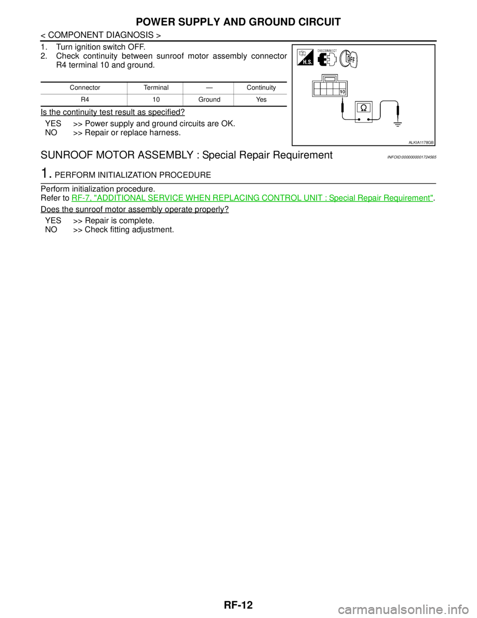
1. Turn ignition switch OFF.
2. Check continuity between sunroof motor assembly connector
R4 terminal 10 and ground.
Is the continuity test result as specified?
YES >> Power supply and ground circuits are OK.
NO >> Repair or replace harness.
SUNROOF MOTOR ASSEMBLY : Special Repair RequirementINFOID:0000000001724565
1. PERFORM INITIALIZATION PROCEDURE
Perform initialization procedure.
Refer to RF-7, "
ADDITIONAL SERVICE WHEN REPLACING CONTROL UNIT : Special Repair Requirement".
Does the sunroof motor assembly operate properly?
YES >> Repair is complete.
NO >> Check fitting adjustment.
Connector Terminal — Continuity
R4 10 Ground Yes
ALKIA1178GB
Page 4547 of 5883
SUNROOF SWITCH CIRCUIT
RF-13
< COMPONENT DIAGNOSIS >
C
D
E
F
G
H
I
J
L
MA
B
RF
N
O
P
SUNROOF SWITCH CIRCUIT
DescriptionINFOID:0000000001724566
A circuit breaker supplies constant battery power to the sunroof motor assembly. The BCM supplies retained
power to the sunroof motor assembly when the key is ON or during retained power operation. The open and
close functions of the sunroof motor assembly are controlled by the sunroof switch.
Component Function CheckINFOID:0000000001724567
1. CHECK SUNROOF MOTOR FUNCTION
Do open and close functions operate normally with the sunroof switch?
Is the inspection result normal?
YES >> Sunroof motor assembly is OK.
NO >> Refer to RF-11, "
SUNROOF MOTOR ASSEMBLY : DiagnosisProcedure".
Diagnosis ProcedureINFOID:0000000001724568
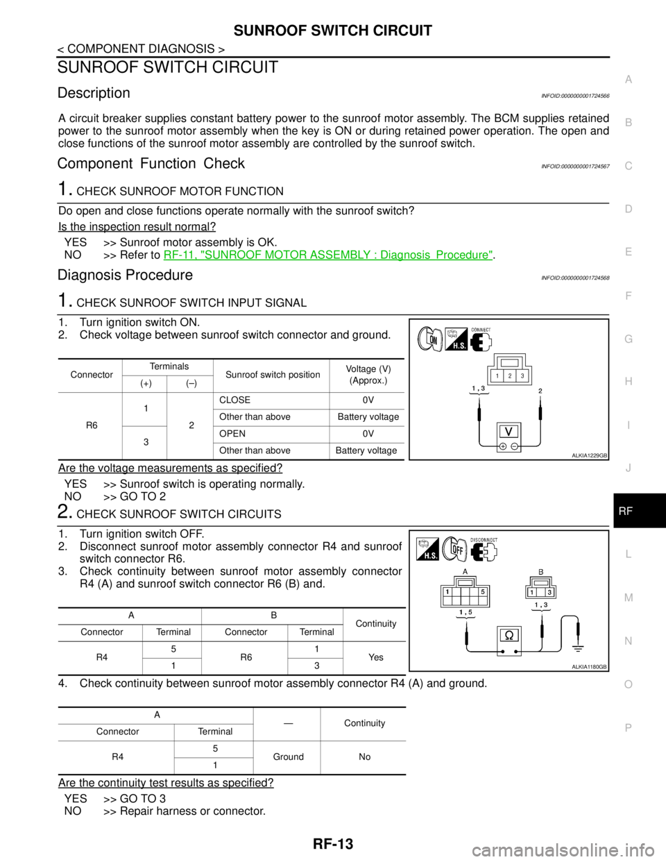
1. CHECK SUNROOF SWITCH INPUT SIGNAL
1. Turn ignition switch ON.
2. Check voltage between sunroof switch connector and ground.
Are the voltage measurements as specified?
YES >> Sunroof switch is operating normally.
NO >> GO TO 2
2. CHECK SUNROOF SWITCH CIRCUITS
1. Turn ignition switch OFF.
2. Disconnect sunroof motor assembly connector R4 and sunroof
switch connector R6.
3. Check continuity between sunroof motor assembly connector
R4 (A) and sunroof switch connector R6 (B) and.
4. Check continuity between sunroof motor assembly connector R4 (A) and ground.
Are the continuity test results as specified?
YES >> GO TO 3
NO >> Repair harness or connector.
ConnectorTe r m i n a l s
Sunroof switch positionVoltage (V)
(Approx.)
(+) (–)
R61
2CLOSE 0V
Other than above Battery voltage
3OPEN 0V
Other than above Battery voltage
ALKIA1229GB
AB
Continuity
Connector Terminal Connector Terminal
R45
R61
Ye s
13
A
—Continuity
Connector Terminal
R45
Ground No
1
ALKIA1180GB
Page 4548 of 5883
RF-14
< COMPONENT DIAGNOSIS >
SUNROOF SWITCH CIRCUIT
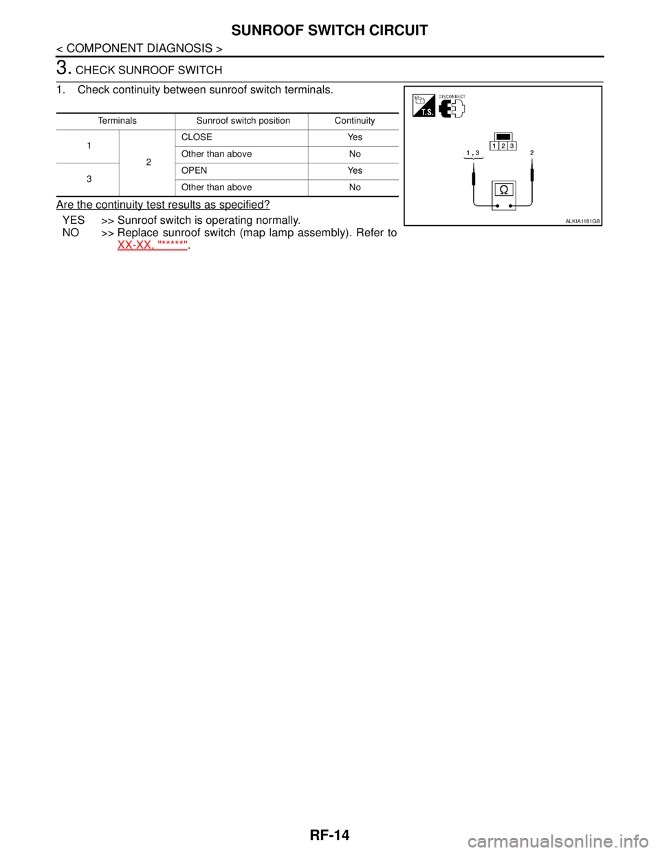
3. CHECK SUNROOF SWITCH
1. Check continuity between sunroof switch terminals.
Are the continuity test results as specified?
YES >> Sunroof switch is operating normally.
NO >> Replace sunroof switch (map lamp assembly). Refer to
XX-XX, "*****"
.
Terminals Sunroof switch position Continuity
1
2CLOSE Yes
Other than above No
3OPEN Yes
Other than above No
ALKIA1181GB
Page 4552 of 5883
RF-18
< ECU DIAGNOSIS >
SUNROOF SYSTEM
SUNROOF SYSTEM
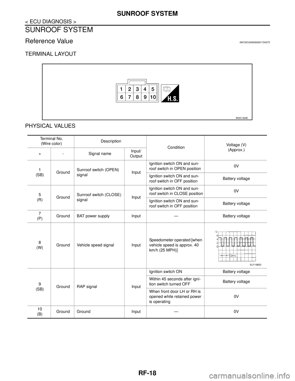
Reference ValueINFOID:0000000001724573
TERMINAL LAYOUT
PHYSICAL VALUES
WIIA1344E
Te r m i n a l N o .
(Wire color)Description
ConditionVoltage (V)
(Approx.)
+ - Signal nameInput/
Output
1
(SB)GroundSunroof switch (OPEN)
signalInputIgnition switch ON and sun-
roof switch in OPEN position0V
Ignition switch ON and sun-
roof switch in OFF positionBattery voltage
5
(R)GroundSunroof switch (CLOSE)
signalInputIgnition switch ON and sun-
roof switch in CLOSE position0V
Ignition switch ON and sun-
roof switch in OFF positionBattery voltage
7
(P)Ground BAT power supply Input — Battery voltage
8
(W)Ground Vehicle speed signal InputSpeedometer operated [when
vehicle speed is approx. 40
km/h (25 MPH)]
9
(SB)Ground RAP signal InputIgnition switch ON Battery voltage
Within 45 seconds after igni-
tion switch turned OFFBattery voltage
When front door LH or RH is
opened while retained power
is operating0V
10
(B)Ground Ground Input — 0V
ELF1080D
Page 4553 of 5883
SUNROOF SYSTEM
RF-19
< ECU DIAGNOSIS >
C
D
E
F
G
H
I
J
L
MA
B
RF
N
O
P
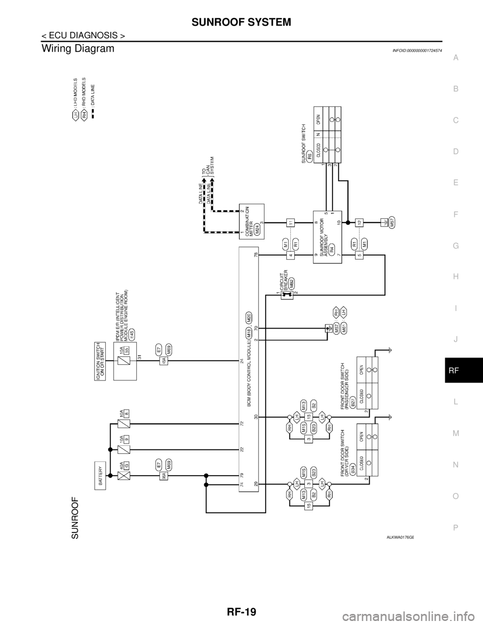
Wiring DiagramINFOID:0000000001724574
ALKWA0176GB