BRC 80 NISSAN TIIDA 2007 Service Repair Manual
[x] Cancel search | Manufacturer: NISSAN, Model Year: 2007, Model line: TIIDA, Model: NISSAN TIIDA 2007Pages: 5883, PDF Size: 78.95 MB
Page 4189 of 5883
![NISSAN TIIDA 2007 Service Repair Manual LAN
ABS BRANCH LINE CIRCUIT
LAN-449
< COMPONENT DIAGNOSIS >[CAN SYSTEM (TYPE 31)]
C
D
E
F
G
H
I
J
K
L B A
O
P N
ABS BRANCH LINE CIRCUIT
Diagnosis ProcedureINFOID:0000000001333600
1.CHECK CONNECTOR
1.](/img/5/57395/w960_57395-4188.png "NISSAN TIIDA 2007 Service Repair Manual LAN
ABS BRANCH LINE CIRCUIT
LAN-449
< COMPONENT DIAGNOSIS >[CAN SYSTEM (TYPE 31)]
C
D
E
F
G
H
I
J
K
L B A
O
P N
ABS BRANCH LINE CIRCUIT
Diagnosis ProcedureINFOID:0000000001333600
1.CHECK CONNECTOR
1.")
LAN
ABS BRANCH LINE CIRCUIT
LAN-449
< COMPONENT DIAGNOSIS >[CAN SYSTEM (TYPE 31)]
C
D
E
F
G
H
I
J
K
L B A
O
P N
ABS BRANCH LINE CIRCUIT
Diagnosis ProcedureINFOID:0000000001333600
1.CHECK CONNECTOR
1. Turn the ignition switch OFF.
2. Disconnect the battery cable from the negative terminal.
3. Check the terminals and connectors of the ABS actuator and electric unit (control unit) for damage, bend
and loose connection (unit side and connector side).
Is the inspection result normal?
YES >> GO TO 2.
NO >> Repair the terminal and connector.
2.CHECK HARNESS FOR OPEN CIRCUIT
1. Disconnect the connector of ABS actuator and electric unit (control unit).
2. Check the resistance between the ABS actuator and electric unit (control unit) harness connector termi-
nals.
Is the measurement value within the specification?
YES >> GO TO 3.
NO >> Repair the ABS actuator and electric unit (control unit) branch line.
3.CHECK POWER SUPPLY AND GROUND CIRCUIT
Check the power supply and the ground circuit of the ABS actuator and electric unit (control unit). Refer to the
following.
ABS models: BRC-36, "
Diagnosis Procedure"
ESP models: BRC-116, "Diagnosis Procedure"
Is the inspection result normal?
YES (Present error)>>Replace the ABS actuator and electric unit (control unit). Refer to the following.
ABS models: BRC-85, "
Removal and Installation"
ESP models: BRC-184, "Removal and Installation"
YES (Past error)>>Error was detected in the ABS actuator and electric unit (control unit) branch line.
NO >> Repair the power supply and the ground circuit.
ABS actuator and electric unit (control unit) harness connector
Resistance (Ω)
Connector No. Terminal No.
E33 26 15 Approx. 54 – 66
Page 4202 of 5883
![NISSAN TIIDA 2007 Service Repair Manual LAN-462
< COMPONENT DIAGNOSIS >[CAN SYSTEM (TYPE 32)]
STRG BRANCH LINE CIRCUIT
STRG BRANCH LINE CIRCUIT
Diagnosis ProcedureINFOID:0000000001333569
INSPECTION PROCEDURE
1.CHECK CONNECTOR
1. Turn the ig](/img/5/57395/w960_57395-4201.png "NISSAN TIIDA 2007 Service Repair Manual LAN-462
< COMPONENT DIAGNOSIS >[CAN SYSTEM (TYPE 32)]
STRG BRANCH LINE CIRCUIT
STRG BRANCH LINE CIRCUIT
Diagnosis ProcedureINFOID:0000000001333569
INSPECTION PROCEDURE
1.CHECK CONNECTOR
1. Turn the ig")
LAN-462
< COMPONENT DIAGNOSIS >[CAN SYSTEM (TYPE 32)]
STRG BRANCH LINE CIRCUIT
STRG BRANCH LINE CIRCUIT
Diagnosis ProcedureINFOID:0000000001333569
INSPECTION PROCEDURE
1.CHECK CONNECTOR
1. Turn the ignition switch OFF.
2. Disconnect the battery cable from the negative terminal.
3. Check the terminals and connectors of the steering angle sensor for damage, bend and loose connection
(unit side and connector side).
Is the inspection result normal?
YES >> GO TO 2.
NO >> Repair the terminal and connector.
2.CHECK HARNESS FOR OPEN CIRCUIT
1. Disconnect the connector of steering angle sensor.
2. Check the resistance between the steering angle sensor harness connector terminals.
Is the measurement value within the specification?
YES >> GO TO 3.
NO >> Repair the steering angle sensor branch line.
3.CHECK POWER SUPPLY AND GROUND CIRCUIT
Check the power supply and the ground circuit of the steering angle sensor. Refer to BRC-142, "
Diagnosis
Procedure".
Is the inspection result normal?
YES (Present error)>>Replace the steering angle sensor. Refer to BRC-186, "Removal and Installation".
YES (Past error)>>Error was detected in the steering angle sensor branch line.
NO >> Repair the power supply and the ground circuit.
Steering angle sensor harness connector
Resistance (Ω)
Connector No. Terminal No.
M80 4 8 Approx. 54 – 66
Page 4204 of 5883
![NISSAN TIIDA 2007 Service Repair Manual LAN-464
< COMPONENT DIAGNOSIS >[CAN SYSTEM (TYPE 32)]
ABS BRANCH LINE CIRCUIT
ABS BRANCH LINE CIRCUIT
Diagnosis ProcedureINFOID:0000000001333571
1.CHECK CONNECTOR
1. Turn the ignition switch OFF.
2. D](/img/5/57395/w960_57395-4203.png "NISSAN TIIDA 2007 Service Repair Manual LAN-464
< COMPONENT DIAGNOSIS >[CAN SYSTEM (TYPE 32)]
ABS BRANCH LINE CIRCUIT
ABS BRANCH LINE CIRCUIT
Diagnosis ProcedureINFOID:0000000001333571
1.CHECK CONNECTOR
1. Turn the ignition switch OFF.
2. D")
LAN-464
< COMPONENT DIAGNOSIS >[CAN SYSTEM (TYPE 32)]
ABS BRANCH LINE CIRCUIT
ABS BRANCH LINE CIRCUIT
Diagnosis ProcedureINFOID:0000000001333571
1.CHECK CONNECTOR
1. Turn the ignition switch OFF.
2. Disconnect the battery cable from the negative terminal.
3. Check the terminals and connectors of the ABS actuator and electric unit (control unit) for damage, bend
and loose connection (unit side and connector side).
Is the inspection result normal?
YES >> GO TO 2.
NO >> Repair the terminal and connector.
2.CHECK HARNESS FOR OPEN CIRCUIT
1. Disconnect the connector of ABS actuator and electric unit (control unit).
2. Check the resistance between the ABS actuator and electric unit (control unit) harness connector termi-
nals.
Is the measurement value within the specification?
YES >> GO TO 3.
NO >> Repair the ABS actuator and electric unit (control unit) branch line.
3.CHECK POWER SUPPLY AND GROUND CIRCUIT
Check the power supply and the ground circuit of the ABS actuator and electric unit (control unit). Refer to the
following.
ABS models: BRC-36, "
Diagnosis Procedure"
ESP models: BRC-116, "Diagnosis Procedure"
Is the inspection result normal?
YES (Present error)>>Replace the ABS actuator and electric unit (control unit). Refer to the following.
ABS models: BRC-85, "
Removal and Installation"
ESP models: BRC-184, "Removal and Installation"
YES (Past error)>>Error was detected in the ABS actuator and electric unit (control unit) branch line.
NO >> Repair the power supply and the ground circuit.
ABS actuator and electric unit (control unit) harness connector
Resistance (Ω)
Connector No. Terminal No.
E33 26 15 Approx. 54 – 66
Page 4332 of 5883
MWI
DTC B2205 VEHICLE SPEED CIRCUIT
MWI-25
< COMPONENT DIAGNOSIS >
C
D
E
F
G
H
I
J
K
L
MB A
O
P
DTC B2205 VEHICLE SPEED CIRCUIT
DescriptionINFOID:0000000001374685
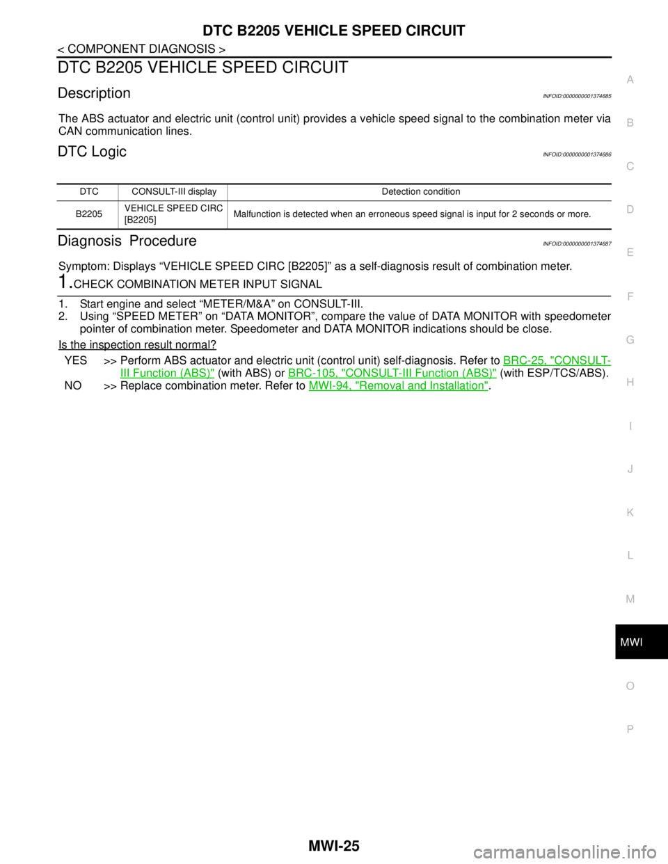
The ABS actuator and electric unit (control unit) provides a vehicle speed signal to the combination meter via
CAN communication lines.
DTC LogicINFOID:0000000001374686
Diagnosis ProcedureINFOID:0000000001374687
Symptom: Displays “VEHICLE SPEED CIRC [B2205]” as a self-diagnosis result of combination meter.
1.CHECK COMBINATION METER INPUT SIGNAL
1. Start engine and select “METER/M&A” on CONSULT-III.
2. Using “SPEED METER” on “DATA MONITOR”, compare the value of DATA MONITOR with speedometer
pointer of combination meter. Speedometer and DATA MONITOR indications should be close.
Is the inspection result normal?
YES >> Perform ABS actuator and electric unit (control unit) self-diagnosis. Refer to BRC-25, "CONSULT-
III Function (ABS)" (with ABS) or BRC-105, "CONSULT-III Function (ABS)" (with ESP/TCS/ABS).
NO >> Replace combination meter. Refer to MWI-94, "
Removal and Installation".
DTC CONSULT-III display Detection condition
B2205VEHICLE SPEED CIRC
[B2205]Malfunction is detected when an erroneous speed signal is input for 2 seconds or more.
Page 4580 of 5883
RSU-8
< ON-VEHICLE REPAIR >
SHOCK ABSORBER
ON-VEHICLE REPAIR
SHOCK ABSORBER
Removal and InstallationINFOID:0000000001724578
REMOVAL
1. Remove rear tires from vehicle using power tool.
2. Remove wheel sensor from wheel hub and bearing assembly and rear suspension beam. Refer to BRC-
83, "Removal and Installation" .
CAUTION:
Do not pull on wheel sensor harness.
3. Remove shock absorber mask from trunk side finisher using a flat-bladed screwdriver. Refer to INT-24,
"Removal and Installation" .
CAUTION:
Wrap the tip of a screwdriver with cloth to avoid damaging components.
4. Set jack under rear suspension beam.
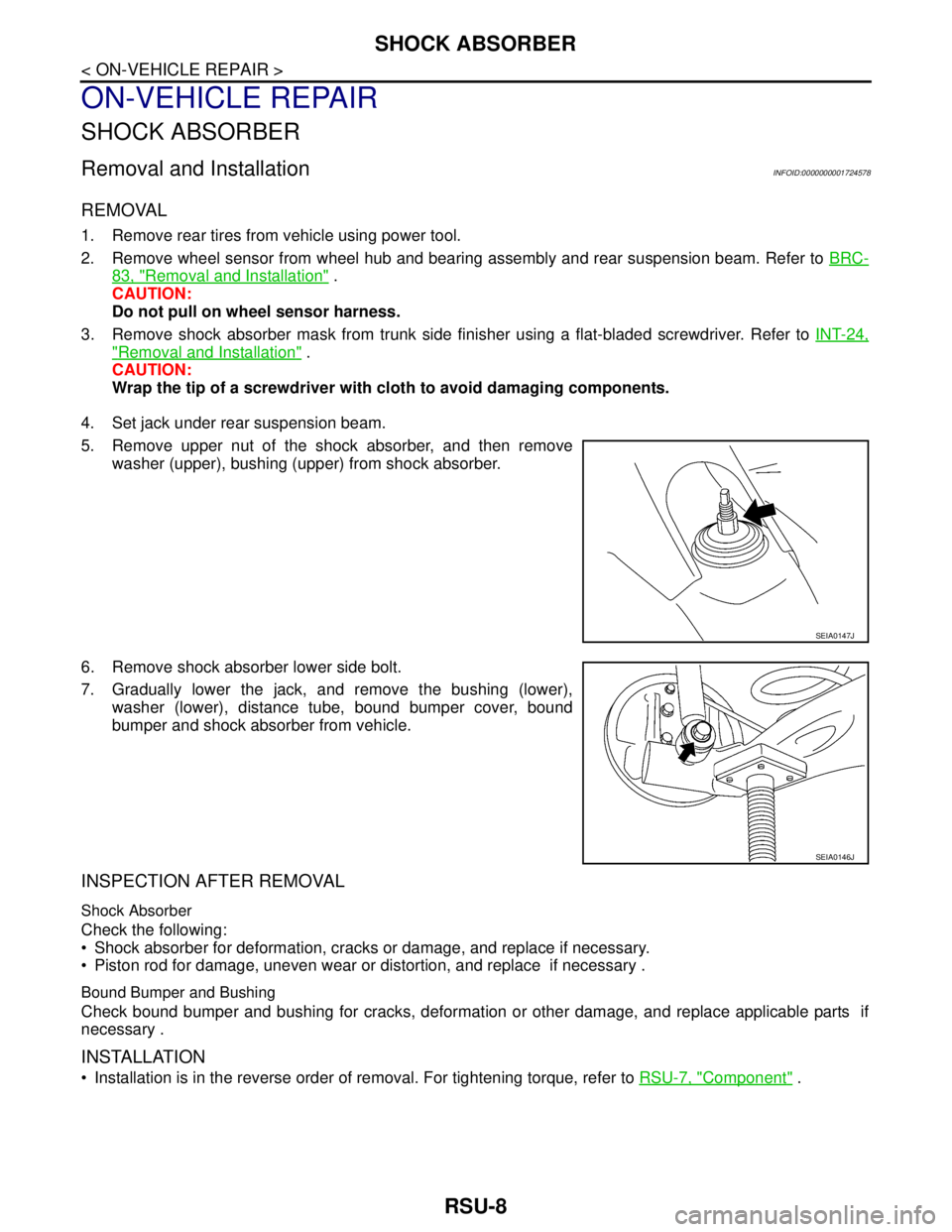
5. Remove upper nut of the shock absorber, and then remove
washer (upper), bushing (upper) from shock absorber.
6. Remove shock absorber lower side bolt.
7. Gradually lower the jack, and remove the bushing (lower),
washer (lower), distance tube, bound bumper cover, bound
bumper and shock absorber from vehicle.
INSPECTION AFTER REMOVAL
Shock Absorber
Check the following:
Shock absorber for deformation, cracks or damage, and replace if necessary.
Piston rod for damage, uneven wear or distortion, and replace if necessary .
Bound Bumper and Bushing
Check bound bumper and bushing for cracks, deformation or other damage, and replace applicable parts if
necessary .
INSTALLATION
Installation is in the reverse order of removal. For tightening torque, refer to RSU-7, "Component" .
SEIA0147J
SEIA0146J
Page 4582 of 5883

RSU-10
< ON-VEHICLE REPAIR >
COIL SPRING
COIL SPRING
Removal and InstallationINFOID:0000000001724579
REMOVAL
1. Remove rear tires from vehicle using power tool.
2. Remove wheel sensor from wheel hub and bearing assembly. Refer to BRC-83, "
Removal and Installa-
tion" .
CAUTION:
Do not pull on wheel sensor harness.
3. Separate brake tube from wheel cylinder. Refer to BR-15, "
Rear Brake Tube and Hose" .
4. Set jack under rear suspension beam.
5. Remove shock absorber lower side bolt. Refer to RSU-8,
"Removal and Installation" .
6. Gradually lower the jack, and then remove coil spring and rear
spring rubber seat (upper and lower).
INSPECTION AFTER REMOVAL
Check coil spring and spring rubber seat for deformation, cracks, and damage, and replace it if a malfunction
is detected.
INSTALLATION
Installation is in the reverse order of removal. For tightening torque, refer to RSU-7, "Component" .
When installing spring, be sure to securely install the spring end
position aligned to flush of rear spring rubber seat (lower) as
shown.
SEIA0146J
SEIA0149J
Page 4583 of 5883

REAR SUSPENSION BEAM
RSU-11
< ON-VEHICLE REPAIR >
C
D
F
G
H
I
J
K
L
MA
B
RSU
N
O
P
REAR SUSPENSION BEAM
Removal and InstallationINFOID:0000000001724580
REMOVAL
1. Remove rear tires from vehicle using power tool.
2. Separate parking brake rear cable from rear drum brake and rear suspension beam. Refer to PB-4, "
On-
Vehicle Service" .
3. Remove wheel sensor and wheel sensor harness from wheel hub and bearing assembly and rear suspen-
sion beam. Refer to BRC-83, "
Removal and Installation" .
4. Remove lock plate and separate brake tube from brake hose.
Refer to BR-15, "
Rear Brake Tube and Hose" .
5. Remove wheel hub and bearing assembly and back plate. Refer
to RAX-6, "
Removal and Installation" .
6. Set jack under rear suspension beam.
7. Remove coil spring (left/right). Refer to RSU-10, "
Removal and
Installation" .
8. Remove bolts between body and rear suspension beam
bracket. Refer to RSU-7, "
Component" .
9. Gradually lower the jack, and then remove rear suspension
beam from vehicle.
10. Remove the rear suspension beam bracket bolt and nut, and then remove rear suspension beam bracket
from rear suspension beam. Refer to RSU-7, "
Component" .
11. Remove brake tube protector from rear suspension beam..
INSPECTION AFTER REMOVAL
Check components for deformation, cracks, and other damage, and replace if necessary.
INSTALLATION
Installation is in the reverse order of removal. For tightening torque, refer to RSU-7, "Component" .
Perform final tightening of rear suspension beam and rear suspen-
sion beam bracket (rubber bushing) under unladen conditions with
tires on level ground.
Refill with new brake fluid and bleed air. Refer to BR-8, "
Bleeding
Brake System" .
Check the following after finishing work.
- Parking brake operation (stroke): Refer to PB-4, "
On-Vehicle Ser-
vice" .
- Wheel sensor harness for proper connection: Refer to BRC-83,
"Removal and Installation" .
MEIA0029E
MEIA0030E
Page 4884 of 5883
![NISSAN TIIDA 2007 Service Repair Manual STC-10
< COMPONENT DIAGNOSIS >[EPS]
C1601 BATTERY POWER SUPPLY
NG >> Check the following. If any items are damaged, repair or replace damaged parts.
60 A fusible link (letter m, located in the fuse](/img/5/57395/w960_57395-4883.png "NISSAN TIIDA 2007 Service Repair Manual STC-10
< COMPONENT DIAGNOSIS >[EPS]
C1601 BATTERY POWER SUPPLY
NG >> Check the following. If any items are damaged, repair or replace damaged parts.
60 A fusible link (letter m, located in the fuse")
STC-10
< COMPONENT DIAGNOSIS >[EPS]
C1601 BATTERY POWER SUPPLY
NG >> Check the following. If any items are damaged, repair or replace damaged parts.
60 A fusible link (letter m, located in the fuse and fusible link box).
10 A fuse [No. 2, located in the fuse block (J/B)].
Harness for short or open between battery and EPS control unit harness connector M54 termi-
nal 17.
Harness for short or open between ignition switch and EPS control unit harness connector M53
terminal 10.
2.CHECK EPS CONTROL UNIT GROUND CIRCUIT
1. Turn ignition switch OFF.
2. Disconnect EPS control unit harness connector.
3. Check continuity between EPS control unit harness connector
M54 terminal 18 and ground.
Also check harness for short to power.
4. Connect EPS control unit harness connector.
OK or NG
OK >> GO TO 3.
NG >> Repair open circuit, short to ground or short to power in
harness or connectors.
3.CHECK DTC
1. Start engine.
Does EPS warning lamp turn OFF?
YES >>INSPECTION END
NO >> Perform self-diagnosis, repair or replace damaged parts. Refer to STC-7, "
CONSULT-III Function
(EPS)".
Special Repair Requirement (Models with ESP)INFOID:0000000001716734
1.ADJUSTMENT OF STEERING ANGLE SENSOR NEUTRAL POSITION
Always perform the neutral position adjustment for the steering angle sensor, when replacing the EPS control
unit. Refer to BRC-90, "
ADJUSTMENT OF STEERING ANGLE SENSOR NEUTRAL POSITION : Descrip-
tion".
>> END
Connector Terminal Continuity
M54 18 Yes
AWGIA0029ZZ
Page 4886 of 5883
![NISSAN TIIDA 2007 Service Repair Manual STC-12
< COMPONENT DIAGNOSIS >[EPS]
C1604 TORQUE SENSOR
Also check harness for short to ground and short to power.
4. Connect EPS control unit harness connector and torque sensor harness connector.
OK](/img/5/57395/w960_57395-4885.png "NISSAN TIIDA 2007 Service Repair Manual STC-12
< COMPONENT DIAGNOSIS >[EPS]
C1604 TORQUE SENSOR
Also check harness for short to ground and short to power.
4. Connect EPS control unit harness connector and torque sensor harness connector.
OK")
STC-12
< COMPONENT DIAGNOSIS >[EPS]
C1604 TORQUE SENSOR
Also check harness for short to ground and short to power.
4. Connect EPS control unit harness connector and torque sensor harness connector.
OK or NG
OK >> GO TO 3.
NG >> Repair or replace damaged parts.
3.CHECK EPS CONTROL UNIT
Check EPS control unit input/output signal. Refer to STC-22, "
EPS Control Unit Input/Output Signal Reference
Va l u e".
OK or NG
OK >> GO TO 4.
NG >> Check EPS control unit pin terminals for damage or loose connection with harness connector. If
any items are damaged, repair or replace damaged parts.
4.CHECK DTC
Perform the self-diagnosis, after driving the vehicle for a while.
OK or NG
OK >>INSPECTION END
NG >> Torque sensor is malfunctioning. Replace steering column assembly. Refer to ST-9, "
Removal
and Installation".
Special Repair Requirement (Models with ESP)INFOID:0000000001730964
1.ADJUSTMENT OF STEERING ANGLE SENSOR NEUTRAL POSITION
Always perform the neutral position adjustment for the steering angle sensor, when replacing the EPS control
unit. Refer to BRC-90, "
ADJUSTMENT OF STEERING ANGLE SENSOR NEUTRAL POSITION : Descrip-
tion".
>> END
Page 4888 of 5883
![NISSAN TIIDA 2007 Service Repair Manual STC-14
< COMPONENT DIAGNOSIS >[EPS]
C1606 EPS MOTOR
OK or NG
OK >> GO TO 4.
NG >> Check EPS control unit pin terminals for damage or loose connection with harness connector. If
any items are damaged,](/img/5/57395/w960_57395-4887.png "NISSAN TIIDA 2007 Service Repair Manual STC-14
< COMPONENT DIAGNOSIS >[EPS]
C1606 EPS MOTOR
OK or NG
OK >> GO TO 4.
NG >> Check EPS control unit pin terminals for damage or loose connection with harness connector. If
any items are damaged,")
STC-14
< COMPONENT DIAGNOSIS >[EPS]
C1606 EPS MOTOR
OK or NG
OK >> GO TO 4.
NG >> Check EPS control unit pin terminals for damage or loose connection with harness connector. If
any items are damaged, repair or replace damaged parts.
4.CHECK DTC
Perform the self-diagnosis, after driving the vehicle for a while.
OK or NG
OK >>INSPECTION END
NG >> GO TO 3.
Special Repair Requirement (Models with ESP)INFOID:0000000001730965
1.ADJUSTMENT OF STEERING ANGLE SENSOR NEUTRAL POSITION
Always perform the neutral position adjustment for the steering angle sensor, when replacing the EPS control
unit. Refer to BRC-90, "
ADJUSTMENT OF STEERING ANGLE SENSOR NEUTRAL POSITION : Descrip-
tion".
>> END