key NISSAN TIIDA 2007 Service Owner's Manual
[x] Cancel search | Manufacturer: NISSAN, Model Year: 2007, Model line: TIIDA, Model: NISSAN TIIDA 2007Pages: 5883, PDF Size: 78.95 MB
Page 172 of 5883

BCS
BCM (BODY CONTROL MODULE)
BCS-37
< ECU DIAGNOSIS >
C
D
E
F
G
H
I
J
K
L B A
O
P N
I-KEY UNLOCK1UNLOCK button of Intelligent Key is not pressed OFF
UNLOCK button of Intelligent Key is pressed ON
KEY SW
2Mechanical key is removed from key cylinder OFF
Mechanical key is inserted to key cylinder ON
KEYLESS LOCK
2LOCK button of key fob is not pressed OFF
LOCK button of key fob is pressed ON
KEYLESS UNLOCK
2UNLOCK button of key fob is not pressed OFF
UNLOCK button of key fob is pressed ON
LIT-SEN FAILLight & rain sensor is in normal condition OK
Light & rain sensor is with internal error NOTOK
OIL PRESS SW Ignition switch OFF or ACC
Engine runningOFF
Ignition switch ON ON
OUT SIDE TEMP
NOTE:
Diesel engine modelsIgnition switch ONApproximately the same as outside
air temperature
PASSING SWOther than lighting switch PASS OFF
Lighting switch PASS ON
PUSH SW
1Return to ignition switch to LOCK position OFF
Press ignition switch ON
REAR DEF SWRear window defogger switch OFF OFF
Rear window defogger switch ON ON
RKE LOCK AND
UNLOCK
2NOTE:
The item is indicated, but not monitoredOFF
ON
RR FOG SWRear fog lamp switch OFF OFF
Rear fog lamp switch ON ON
RR WASHER SW
3Rear washer switch OFF OFF
Rear washer switch ON ON
RR WIPER INT
3Rear wiper switch OFF OFF
Rear wiper switch INT ON
RR WIPER ON
3 Rear wiper switch OFF OFF
Rear wiper switch ON ON
RR WIPER STOP
3Rear wiper stop position OFF
Other than rear wiper stop position ON
TAIL LAMP SWLighting switch OFF OFF
Lighting switch 1ST ON
TRNK OPNR SWWhen back door opener switch is not pressed OFF
When back door opener switch is pressed ON
TURN SIGNAL LTurn signal switch OFF OFF
Turn signal switch LH ON
TURN SIGNAL RTurn signal switch OFF OFF
Turn signal switch RH ON
UNLOCK WITH DRNOTE:
The item is indicated, but not monitoredOFF
ON
VEHICLE SPEED While driving Equivalent to speedometer reading Monitor Item Condition Value/Status
Page 173 of 5883

BCS-38
< ECU DIAGNOSIS >
BCM (BODY CONTROL MODULE)
1: With Intelligent Key
2: With remote keyless entry system
3: Hatchback
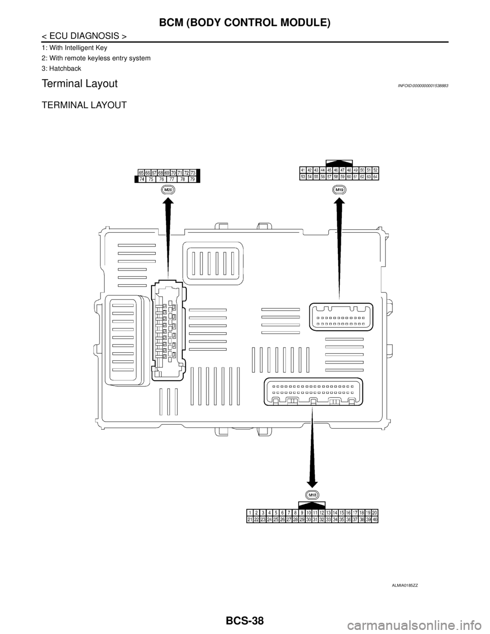
Terminal LayoutINFOID:0000000001538883
TERMINAL LAYOUT
ALMIA0185ZZ
Page 174 of 5883

BCS
BCM (BODY CONTROL MODULE)
BCS-39
< ECU DIAGNOSIS >
C
D
E
F
G
H
I
J
K
L B A
O
P N
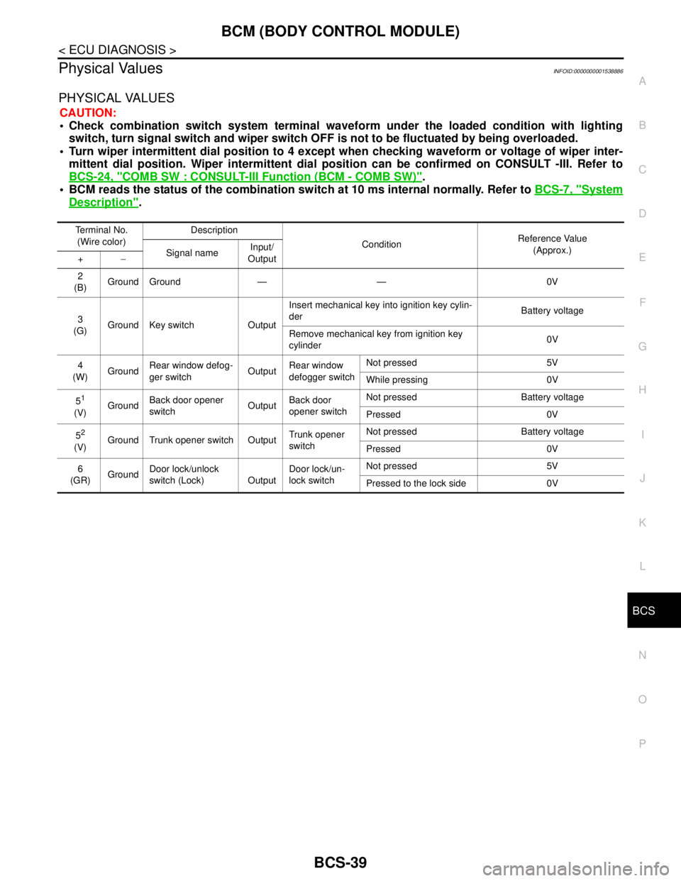
Physical ValuesINFOID:0000000001538886
PHYSICAL VALUES
CAUTION:
Check combination switch system terminal waveform under the loaded condition with lighting
switch, turn signal switch and wiper switch OFF is not to be fluctuated by being overloaded.
Turn wiper intermittent dial position to 4 except when checking waveform or voltage of wiper inter-
mittent dial position. Wiper intermittent dial position can be confirmed on CONSULT -III. Refer to
BCS-24, "
COMB SW : CONSULT-III Function (BCM - COMB SW)".
BCM reads the status of the combination switch at 10 ms internal normally. Refer to BCS-7, "
System
Description".
Terminal No.
(Wire color)Description
ConditionReference Value
(Approx.)
Signal nameInput/
Output +−
2
(B)Ground Ground — — 0V
3
(G)Ground Key switch OutputInsert mechanical key into ignition key cylin-
derBattery voltage
Remove mechanical key from ignition key
cylinder0V
4
(W)GroundRear window defog-
ger switchOutputRear window
defogger switchNot pressed 5V
While pressing 0V
5
1
(V)GroundBack door opener
switchOutputBack door
opener switchNot pressed Battery voltage
Pressed 0V
5
2
(V)Ground Trunk opener switch OutputTrunk opener
switchNot pressed Battery voltage
Pressed 0V
6
(GR)GroundDoor lock/unlock
switch (Lock) OutputDoor lock/un-
lock switchNot pressed 5V
Pressed to the lock side 0V
Page 182 of 5883

BCS
BCM (BODY CONTROL MODULE)
BCS-47
< ECU DIAGNOSIS >
C
D
E
F
G
H
I
J
K
L B A
O
P N
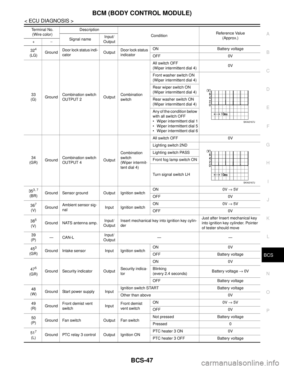
324
(LG)GroundDoor lock status indi-
catorOutputDoor lock status
indicatorON Battery voltage
OFF 0V
33
(G)GroundCombination switch
OUTPUT 2OutputCombination
switchAll switch OFF
(Wiper intermittent dial 4)0V
Front washer switch ON
(Wiper intermittent dial 4)
Rear wiper switch ON
(Wiper intermittent dial 4)
Rear washer switch ON
(Wiper intermittent dial 4)
Any of the condition below
with all switch OFF
Wiper intermittent dial 1
Wiper intermittent dial 5
Wiper intermittent dial 6
34
(GR)GroundCombination switch
OUTPUT 4OutputCombination
switch
(Wiper intermit-
tent dial 4)All switch OFF 0V
Lighting switch 2ND
Lighting switch PASS
Front fog lamp switch ON
Turn signal switch LH
35
3, 7
(BR)Ground Sensor ground Output Ignition switchON 0V → 5V
OFF 0V
36
7
(V)GroundAmbient sensor sig-
nalInput Ignition switchON 0V → 5V
OFF 0V
38
5
(V)Ground NATS antenna amp.Input/
OutputInsert mechanical key into ignition key cylin-
derJust after Insert mechanical key
into ignition key cylinder. Pointer
of tester should move
39
(P)—CAN-LInput/
Output——
45
3
(GR)Ground Intake sensor Input Ignition switchON 0V
OFF Battery voltage
47
5
(GR)Ground Security indicator OutputSecurity indica-
torON 0V
Blinking
(every 2.4 seconds)Battery voltage → 0V
OFF Battery voltage
48
(W)Ground Start power supply InputIgnition switch START Battery voltage
Other than above 0V
49
(R)GroundFront demist vent
switchInputFront demist
vent switchON 0V → 5V
OFF 0V
50
(P)Ground Fan switch Output Fan switchNot pressed Battery voltage
Pressed 0
51
7
(L)Ground PTC relay 3 control Output Ignition ONPTC heater 3 ON 0V
PTC heater 3 OFF Battery voltage Terminal No.
(Wire color)Description
ConditionReference Value
(Approx.)
Signal nameInput/
Output +−
SKIA2167J
SKIA2167J
Page 184 of 5883

BCS
BCM (BODY CONTROL MODULE)
BCS-49
< ECU DIAGNOSIS >
C
D
E
F
G
H
I
J
K
L B A
O
P N
1: Hatchback
2: Sedan
3: Manual A/C
4: Superlock
5: Remote keyless entry
6: Intelligent Key
7: LHD diesel69
(G)Ground Rear fog lamp OutputLighting switch
1ST and front
fog lamp switch
ONRear fog lamp switch OFF 0V
Rear fog lamp switch ON Battery voltage
70
(B)Ground Ground — — 0V
71
1
(V)Ground Rear wiper motor OutputRear wiper switch OFF 0V
Rear wiper switch ON Battery voltage
72
(LG)GroundBattery power sup-
plyInput — Battery voltage
73
(R)GroundInterior room lamp
power supplyOutputAfter passing the interior room lamp battery
saver operation time0V
Any other time after passing the interior room
lamp battery saver operation timeBattery voltage
74
(Y)GroundBattery power sup-
plyInput — Battery voltage
75
4
(V)Ground Super lock OutputWhen lock button of keyfob or Intelligent Key
is not pressed 0V
When lock button of keyfob or Intelligent Key
is pressed Battery voltage
76
(G)Ground Driver door unlock OutputDoor lock/un-
lock switchPressed to the unlock side Battery voltage
Pressed to the lock side 0V
77
(SB)Ground Door lock (All) OutputDoor lock/un-
lock switchPressed to the unlock side 0V
Pressed to the lock side Battery voltage
78
(L)GroundPower window pow-
er supplyOutput Ignition switchOFF or ACC 0V
ON Battery voltage
79
(Y)GroundBattery power sup-
plyInput — Battery voltage Terminal No.
(Wire color)Description
ConditionReference Value
(Approx.)
Signal nameInput/
Output +−
Page 192 of 5883

BCS
BCM (BODY CONTROL MODULE)
BCS-57
< ON-VEHICLE REPAIR >
C
D
E
F
G
H
I
J
K
L B A
O
P N
ON-VEHICLE REPAIR
BCM (BODY CONTROL MODULE)
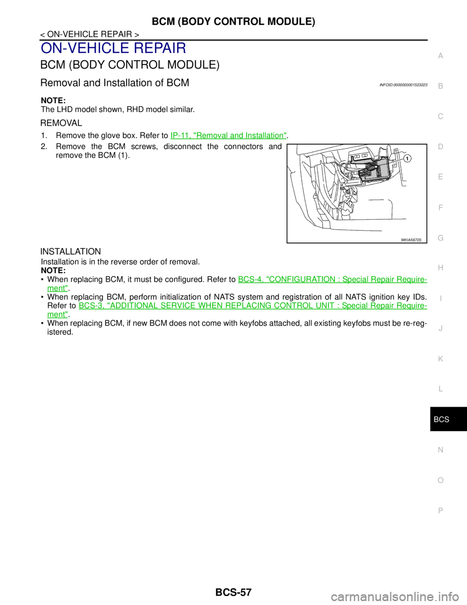
Removal and Installation of BCMINFOID:0000000001523223
NOTE:
The LHD model shown, RHD model similar.
REMOVAL
1. Remove the glove box. Refer to IP-11, "Removal and Installation".
2. Remove the BCM screws, disconnect the connectors and
remove the BCM (1).
INSTALLATION
Installation is in the reverse order of removal.
NOTE:
When replacing BCM, it must be configured. Refer to BCS-4, "
CONFIGURATION : Special Repair Require-
ment".
When replacing BCM, perform initialization of NATS system and registration of all NATS ignition key IDs.
Refer to BCS-3, "
ADDITIONAL SERVICE WHEN REPLACING CONTROL UNIT : Special Repair Require-
ment".
When replacing BCM, if new BCM does not come with keyfobs attached, all existing keyfobs must be re-reg-
istered.
WKIA5672E
Page 260 of 5883
![NISSAN TIIDA 2007 Service Owners Manual DIAGNOSIS SYSTEM [ABS ACTUATOR AND ELECTRIC UNIT (CONTROL
UNIT)]
BRC-27
< FUNCTION DIAGNOSIS >[ABS]
C
D
E
G
H
I
J
K
L
MA
B
BRC
N
O
P
CV1
(ON/OFF)––×Front side switch-over solenoid
valve (cut va NISSAN TIIDA 2007 Service Owners Manual DIAGNOSIS SYSTEM [ABS ACTUATOR AND ELECTRIC UNIT (CONTROL
UNIT)]
BRC-27
< FUNCTION DIAGNOSIS >[ABS]
C
D
E
G
H
I
J
K
L
MA
B
BRC
N
O
P
CV1
(ON/OFF)––×Front side switch-over solenoid
valve (cut va](/img/5/57395/w960_57395-259.png)
DIAGNOSIS SYSTEM [ABS ACTUATOR AND ELECTRIC UNIT (CONTROL
UNIT)]
BRC-27
< FUNCTION DIAGNOSIS >[ABS]
C
D
E
G
H
I
J
K
L
MA
B
BRC
N
O
P
CV1
(ON/OFF)––×Front side switch-over solenoid
valve (cut valve) (ON/OFF) status is
displayed.
CV2
(ON/OFF)––×Rear side switch-over solenoid
valve (cut-valve) (ON/OFF) status is
displayed.
SV1
(ON/OFF)––×Front side switch-over solenoid
valve (suction valve) (ON/OFF) sta-
tus is displayed.
SV2
(ON/OFF)––×Rear side switch-over solenoid
valve (suction valve) (ON/OFF) sta-
tus is displayed.
VDC FAIL SIG
(ON/OFF)––×VDC fail signal (ON/OFF) status is
displayed.
TCS FAIL SIG
(ON/OFF)––×TCS fail signal (ON/OFF) status is
displayed.
ABS FAIL SIG
(ON/OFF)––×ABS fail signal (ON/OFF) status is
displayed.
EBD FAIL SIG
(ON/OFF)––×EBD fail signal (ON/OFF) status is
displayed.
FLUID LEV SW
(ON/OFF)×–×Brake fluid level switch (ON/OFF)
status is displayed.
EBD SIGNAL
(ON/OFF)––×EBD operation (ON/OFF) status is
displayed.
ABS SIGNAL
(ON/OFF)––×ABS operation (ON/OFF) status is
displayed.
TCS SIGNAL
(ON/OFF)––×TCS operation (ON/OFF) status is
displayed.
VDC SIGNAL
(ON/OFF)––×VDC operation (ON/OFF) status is
displayed.
EBD WARN LAMP – –×Brake warning lamp (ON/OFF) sta-
tus is displayed.
SLCT LVR POSI×××Shift position judged by PNP switch
signal.
R POSI SIG – –×Shift position judged by PNP switch
signal.
2WD/4WD – –×It recognizes on software whether it
is 2WD and whether it is in 4WD
state.
BST OPER SIG – –×
Active booster operation (ON/OFF)
status is displayed.
PRESS SENSOR×–×Brake pressure detected by pres-
sure sensor is displayed.
CRANKING SIG – –×The input state of the key SW
START position signal is displayed.
PRESS SEN 2 – –×Brake pressure detected by pres-
sure sensor is displayed.
DELTA S SEN – –×The amount of stroke sensor move-
ments in the active booster detected
by DELTA S SEN is displayed. Item
(Unit)Data monitor item selection
Remarks
ECU INPUT
SIGNALSMAIN
SIGNALSSELECTION
FROM MENU
Page 340 of 5883
![NISSAN TIIDA 2007 Service Owners Manual DIAGNOSIS SYSTEM [ABS ACTUATOR AND ELECTRIC UNIT (CONTROL
UNIT)]
BRC-107
< FUNCTION DIAGNOSIS >[ESP/TCS/ABS]
C
D
E
G
H
I
J
K
L
MA
B
BRC
N
O
P
CV1
(ON/OFF)––×Front side switch-over solenoid
valv NISSAN TIIDA 2007 Service Owners Manual DIAGNOSIS SYSTEM [ABS ACTUATOR AND ELECTRIC UNIT (CONTROL
UNIT)]
BRC-107
< FUNCTION DIAGNOSIS >[ESP/TCS/ABS]
C
D
E
G
H
I
J
K
L
MA
B
BRC
N
O
P
CV1
(ON/OFF)––×Front side switch-over solenoid
valv](/img/5/57395/w960_57395-339.png)
DIAGNOSIS SYSTEM [ABS ACTUATOR AND ELECTRIC UNIT (CONTROL
UNIT)]
BRC-107
< FUNCTION DIAGNOSIS >[ESP/TCS/ABS]
C
D
E
G
H
I
J
K
L
MA
B
BRC
N
O
P
CV1
(ON/OFF)––×Front side switch-over solenoid
valve (cut valve) (ON/OFF) status is
displayed.
CV2
(ON/OFF)––×Rear side switch-over solenoid
valve (cut-valve) (ON/OFF) status is
displayed.
SV1
(ON/OFF)––×Front side switch-over solenoid
valve (suction valve) (ON/OFF) sta-
tus is displayed.
SV2
(ON/OFF)––×Rear side switch-over solenoid
valve (suction valve) (ON/OFF) sta-
tus is displayed.
VDC FAIL SIG
(ON/OFF)––×VDC fail signal (ON/OFF) status is
displayed.
TCS FAIL SIG
(ON/OFF)––×TCS fail signal (ON/OFF) status is
displayed.
ABS FAIL SIG
(ON/OFF)––×ABS fail signal (ON/OFF) status is
displayed.
EBD FAIL SIG
(ON/OFF)––×EBD fail signal (ON/OFF) status is
displayed.
FLUID LEV SW
(ON/OFF)×–×Brake fluid level switch (ON/OFF)
status is displayed.
EBD SIGNAL
(ON/OFF)––×EBD operation (ON/OFF) status is
displayed.
ABS SIGNAL
(ON/OFF)––×ABS operation (ON/OFF) status is
displayed.
TCS SIGNAL
(ON/OFF)––×TCS operation (ON/OFF) status is
displayed.
VDC SIGNAL
(ON/OFF)––×VDC operation (ON/OFF) status is
displayed.
EBD WARN LAMP – –×Brake warning lamp (ON/OFF) sta-
tus is displayed.
SLCT LVR POSI×××Shift position judged by PNP switch
signal.
R POSI SIG – –×Shift position judged by PNP switch
signal.
2WD/4WD – –×It recognizes on software whether it
is 2WD and whether it is in 4WD
state.
BST OPER SIG – –×
Active booster operation (ON/OFF)
status is displayed.
PRESS SENSOR×–×Brake pressure detected by pres-
sure sensor is displayed.
CRANKING SIG – –×The input state of the key SW
START position signal is displayed.
PRESS SEN 2 – –×Brake pressure detected by pres-
sure sensor is displayed.
DELTA S SEN – –×The amount of stroke sensor move-
ments in the active booster detected
by DELTA S SEN is displayed. Item
(Unit)Data monitor item selection
Remarks
ECU INPUT
SIGNALSMAIN
SIGNALSSELECTION
FROM MENU
Page 489 of 5883
![NISSAN TIIDA 2007 Service Owners Manual CO-8
< PRECAUTION >[HR16DE]
PRECAUTIONS
PRECAUTION
PRECAUTIONS
Precaution for Supplemental Restraint System (SRS) "AIR BAG" and "SEAT BELT
PRE-TENSIONER"
INFOID:0000000001534589
The Supplemental Rest NISSAN TIIDA 2007 Service Owners Manual CO-8
< PRECAUTION >[HR16DE]
PRECAUTIONS
PRECAUTION
PRECAUTIONS
Precaution for Supplemental Restraint System (SRS) "AIR BAG" and "SEAT BELT
PRE-TENSIONER"
INFOID:0000000001534589
The Supplemental Rest](/img/5/57395/w960_57395-488.png)
CO-8
< PRECAUTION >[HR16DE]
PRECAUTIONS
PRECAUTION
PRECAUTIONS
Precaution for Supplemental Restraint System (SRS) "AIR BAG" and "SEAT BELT
PRE-TENSIONER"
INFOID:0000000001534589
The Supplemental Restraint System such as “AIR BAG” and “SEAT BELT PRE-TENSIONER”, used along
with a front seat belt, helps to reduce the risk or severity of injury to the driver and front passenger for certain
types of collision. Information necessary to service the system safely is included in the SR and SB section of
this Service Manual.
WARNING:
• To avoid rendering the SRS inoperative, which could increase the risk of personal injury or death in
the event of a collision which would result in air bag inflation, all maintenance must be performed by
an authorized NISSAN/INFINITI dealer.
Improper maintenance, including incorrect removal and installation of the SRS, can lead to personal
injury caused by unintentional activation of the system. For removal of Spiral Cable and Air Bag
Module, see the SR section.
Do not use electrical test equipment on any circuit related to the SRS unless instructed to in this
Service Manual. SRS wiring harnesses can be identified by yellow and/or orange harnesses or har-
ness connectors.
Precaution Necessary for Steering Wheel Rotation After Battery Disconnect
INFOID:0000000001534590
NOTE:
This Procedure is applied only to models with Intelligent Key system and NATS (NISSAN ANTI-THEFT SYS-
TEM).
Remove and install all control units after disconnecting both battery cables with the ignition knob in the
″LOCK″ position.
Always use CONSULT-II to perform self-diagnosis as a part of each function inspection after finishing work.
If DTC is detected, perform trouble diagnosis according to self-diagnostic results.
For models equipped with the Intelligent Key system and NATS, an electrically controlled steering lock mech-
anism is adopted on the key cylinder.
For this reason, if the battery is disconnected or if the battery is discharged, the steering wheel will lock and
steering wheel rotation will become impossible.
If steering wheel rotation is required when battery power is interrupted, follow the procedure below before
starting the repair operation.
OPERATION PROCEDURE
1. Connect both battery cables.
NOTE:
Supply power using jumper cables if battery is discharged.
2. Use the Intelligent Key or mechanical key to turn the ignition switch to the ″ACC″ position. At this time, the
steering lock will be released.
3. Disconnect both battery cables. The steering lock will remain released and the steering wheel can be
rotated.
4. Perform the necessary repair operation.
5. When the repair work is completed, return the ignition switch to the ″LOCK″ position before connecting
the battery cables. (At this time, the steering lock mechanism will engage.)
6. Perform a self-diagnosis check of all control units using CONSULT-II.
Precaution for Liquid GasketINFOID:0000000001534591
REMOVAL OF LIQUID GASKET SEALING
After removing nuts and bolts, separate the mating surface, using Tool and remove old liquid gasket sealing.
Page 513 of 5883
![NISSAN TIIDA 2007 Service Owners Manual CO-32
< PRECAUTION >[MR18DE]
PRECAUTIONS
PRECAUTION
PRECAUTIONS
Precaution for Supplemental Restraint System (SRS) "AIR BAG" and "SEAT BELT
PRE-TENSIONER"
INFOID:0000000001516585
The Supplemental Res NISSAN TIIDA 2007 Service Owners Manual CO-32
< PRECAUTION >[MR18DE]
PRECAUTIONS
PRECAUTION
PRECAUTIONS
Precaution for Supplemental Restraint System (SRS) "AIR BAG" and "SEAT BELT
PRE-TENSIONER"
INFOID:0000000001516585
The Supplemental Res](/img/5/57395/w960_57395-512.png)
CO-32
< PRECAUTION >[MR18DE]
PRECAUTIONS
PRECAUTION
PRECAUTIONS
Precaution for Supplemental Restraint System (SRS) "AIR BAG" and "SEAT BELT
PRE-TENSIONER"
INFOID:0000000001516585
The Supplemental Restraint System such as “AIR BAG” and “SEAT BELT PRE-TENSIONER”, used along
with a front seat belt, helps to reduce the risk or severity of injury to the driver and front passenger for certain
types of collision. Information necessary to service the system safely is included in the SR and SB section of
this Service Manual.
WARNING:
To avoid rendering the SRS inoperative, which could increase the risk of personal injury or death in
the event of a collision which would result in air bag inflation, all maintenance must be performed by
an authorized NISSAN/INFINITI dealer.
Improper maintenance, including incorrect removal and installation of the SRS, can lead to personal
injury caused by unintentional activation of the system. For removal of Spiral Cable and Air Bag
Module, see the SR section.
Do not use electrical test equipment on any circuit related to the SRS unless instructed to in this
Service Manual. SRS wiring harnesses can be identified by yellow and/or orange harnesses or har-
ness connectors.
Precaution Necessary for Steering Wheel Rotation After Battery Disconnect
INFOID:0000000001337832
NOTE:
This Procedure is applied only to models with Intelligent Key system and NATS (NISSAN ANTI-THEFT SYS-
TEM).
Remove and install all control units after disconnecting both battery cables with the ignition knob in the
″LOCK″ position.
Always use CONSULT-II to perform self-diagnosis as a part of each function inspection after finishing work.
If DTC is detected, perform trouble diagnosis according to self-diagnostic results.
For models equipped with the Intelligent Key system and NATS, an electrically controlled steering lock mech-
anism is adopted on the key cylinder.
For this reason, if the battery is disconnected or if the battery is discharged, the steering wheel will lock and
steering wheel rotation will become impossible.
If steering wheel rotation is required when battery power is interrupted, follow the procedure below before
starting the repair operation.
OPERATION PROCEDURE
1. Connect both battery cables.
NOTE:
Supply power using jumper cables if battery is discharged.
2. Use the Intelligent Key or mechanical key to turn the ignition switch to the ″ACC″ position. At this time, the
steering lock will be released.
3. Disconnect both battery cables. The steering lock will remain released and the steering wheel can be
rotated.
4. Perform the necessary repair operation.
5. When the repair work is completed, return the ignition switch to the ″LOCK″ position before connecting
the battery cables. (At this time, the steering lock mechanism will engage.)
6. Perform a self-diagnosis check of all control units using CONSULT-II.
Precaution for Liquid GasketINFOID:0000000001337833
REMOVAL OF LIQUID GASKET SEALING
After removing nuts and bolts, separate the mating surface, using Tool and remove old liquid gasket sealing.