steering NISSAN TIIDA 2007 Service Repair Manual
[x] Cancel search | Manufacturer: NISSAN, Model Year: 2007, Model line: TIIDA, Model: NISSAN TIIDA 2007Pages: 5883, PDF Size: 78.95 MB
Page 5699 of 5883
![NISSAN TIIDA 2007 Service Repair Manual VTL-38
< ON-VEHICLE REPAIR >[MANUAL AIR CONDITIONER]
A/C UNIT ASSEMBLY
7. Remove console box assembly. Refer to IP-11, "Removal and Installation" .
8. Remove instrument stay nuts (A) and harness clamp NISSAN TIIDA 2007 Service Repair Manual VTL-38
< ON-VEHICLE REPAIR >[MANUAL AIR CONDITIONER]
A/C UNIT ASSEMBLY
7. Remove console box assembly. Refer to IP-11, "Removal and Installation" .
8. Remove instrument stay nuts (A) and harness clamp](/img/5/57395/w960_57395-5698.png)
VTL-38
< ON-VEHICLE REPAIR >[MANUAL AIR CONDITIONER]
A/C UNIT ASSEMBLY
7. Remove console box assembly. Refer to IP-11, "Removal and Installation" .
8. Remove instrument stay nuts (A) and harness clamps (B), and
then remove instrument stay (1).
9. Disconnect thermo control amp. connector (1).
10. Remove instrument panel and pad. Refer to IP-11, "
Removal and Installation".
11. Remove side ventilator ducts. Refer to VTL-48, "
Removal and Installation".
12. Remove center ventilator ducts. Refer to VTL-48, "
Removal and Installation".
13. Remove side kicking plates. Refer to INT-20, "
Removal and Installation".
14. Disconnect the fuel filler door cable and the rear hatch door cable.
15. Remove A/C unit assembly bolts, steering member bolts, steering column nuts and harness clips.
16. Remove steering member, and then remove A/C unit assembly.
INSTALLATION
Installation is in the reverse order of removal.
Fill the cooling system. Refer to CO-11, "
Changing Engine Coolant" (HR16DE), CO-35, "Changing Engine
Coolant" (MR18DE), CO-58, "Refilling" (K9K).
Recharge the refrigerant.
CAUTION:
Replace O-rings for A/C piping with new ones, and apply compressor oil when installing.
When recharging refrigerant, check for leaks.
SJIA0646E
SJIA0647E
A/C unit assembly bolt : 6.9 N·m (0.7 kg-m, 61 in-lb)
Steering member bolt : 12 N·m (1.25 kg-m, 9 ft-lb)
Steering column nut : Refer to ST-9, "
Removal and Installation".
Page 5707 of 5883
![NISSAN TIIDA 2007 Service Repair Manual VTL-46
< ON-VEHICLE REPAIR >[MANUAL AIR CONDITIONER]
AIR MIX DOOR
AIR MIX DOOR
Air Mix Door Cable AdjustmentINFOID:0000000001696538
1. Remove steering member. Refer to ST-9, "Removal and Installation" NISSAN TIIDA 2007 Service Repair Manual VTL-46
< ON-VEHICLE REPAIR >[MANUAL AIR CONDITIONER]
AIR MIX DOOR
AIR MIX DOOR
Air Mix Door Cable AdjustmentINFOID:0000000001696538
1. Remove steering member. Refer to ST-9, "Removal and Installation"](/img/5/57395/w960_57395-5706.png)
VTL-46
< ON-VEHICLE REPAIR >[MANUAL AIR CONDITIONER]
AIR MIX DOOR
AIR MIX DOOR
Air Mix Door Cable AdjustmentINFOID:0000000001696538
1. Remove steering member. Refer to ST-9, "Removal and Installation".
2. Remove outer cable of air mix door cable (1) from clamp (A).
3. Set temperature control dial to full cold position.
4. Push air mix door lever (2) in the direction shown by arrow, and
then carefully pull outer cable toward controller side, and install
clamp (A).
5. Operate temperature control dial to insure that inner cable
moves smoothly.
CAUTION:
When clamping the outer cable, do not move the inner
cable.
SJIA1150E
Page 5753 of 5883

WCS-38
< ECU DIAGNOSIS >
COMBINATION METER
11 LG Brake fluid level switch ONBrake fluid level low 0
Brake fluid level normal Battery voltage
16 VSteering switch (trip comput-
er) signalONPress the steering switch (trip
computer)0
Other than the above 5
19 V Ambient sensor signal ON —
20 BR Ambient sensor ground ON — 0
21
BGround — — 0 22
23
24 V Fuel level sensor ground (-) ON — 0
25 RAuto A/C sense signal (with
auto A/C)ON — 5V
27 G Battery power supply OFF — Battery voltage
28 SB Ignition switch ON or START ON — Battery voltage
30 G Stop lamp switch ONBrake pedal depressed Battery voltage
Brake pedal released 0
31 V A/T N-range input (with A/T) ONTransmission gear selector lever
in N positionBattery voltage
Transmission gear selector lever
other than N position0
32 W A/T P-range input (with A/T) ONTransmission gear selector lever
in P positionBattery voltage
Transmission gear selector lever
other than P position0
33 Y A/T PN output (with A/T) ONTransmission gear selector lever
in P or N position0
Transmission gear selector lever
other than P or N positionBattery voltage
35 BREngine coolant temperature
signal outputONAt idle [after warming up, approx.
80°C (176°F)]
NOTE:
The waveforms vary depending
on engine coolant temperature. Te r -
mi-
nal
No.Wire
colorItemCondition
Reference value (V)
(Approx.) Ignition
switchOperation or condition
JSNIA0014GB
SKIB3651J
Page 5770 of 5883

WCS
COMBINATION METER
WCS-55
< ECU DIAGNOSIS >
C
D
E
F
G
H
I
J
K
L
MB A
O
P
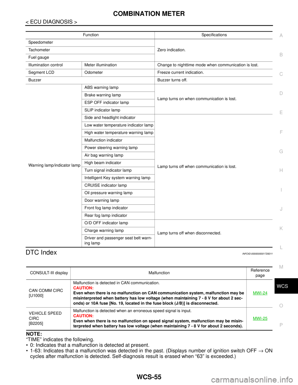
DTC IndexINFOID:0000000001728311
NOTE:
“TIME” indicates the following.
0: Indicates that a malfunction is detected at present.
1-63: Indicates that a malfunction was detected in the past. (Displays number of ignition switch OFF → ON
cycles after malfunction is detected. Self-diagnosis result is erased when “63” is exceeded.)
Function Specifications
Speedometer
Zero indication. Tachometer
Fuel gauge
Illumination control Meter illumination Change to nighttime mode when communication is lost.
Segment LCD Odometer Freeze current indication.
Buzzer Buzzer turns off.
Warning lamp/indicator lampABS warning lamp
Lamp turns on when communication is lost. Brake warning lamp
ESP OFF indicator lamp
SLIP indicator lamp
Side and headlight indicator
Lamp turns off when communication is lost. Low water temperature indicator lamp
High water temperature warning lamp
Malfunction indicator
Power steering warning lamp
Air bag warning lamp
High beam indicator
Turn signal indicator lamp
Intelligent Key system warning lamp
CRUISE indicator lamp
Oil pressure warning lamp
Door warning lamp
Front fog lamp indicator
Rear fog lamp indicator
O/D OFF indicator lamp
Lamp turns off when disconnected. Charge warning lamp
Driver and passenger seat belt warn-
ing lamp
CONSULT-III display MalfunctionReference
page
CAN COMM CIRC
[U1000]Malfunction is detected in CAN communication.
CAUTION:
Even when there is no malfunction on CAN communication system, malfunction may be
misinterpreted when battery has low voltage (when maintaining 7 - 8 V for about 2 sec-
onds) or 10A fuse [No. 19, located in the fuse block (J/B)] is disconnected.MWI-24
VEHICLE SPEED
CIRC
[B2205]Malfunction is detected when an erroneous speed signal is input.
CAUTION:
Even when there is no malfunction on speed signal system, malfunction may be misin-
terpreted when battery has low voltage (when maintaining 7 - 8 V for about 2 seconds). MWI-25
Page 5799 of 5883

WT-4
< SYMPTOM DIAGNOSIS >
NOISE, VIBRATION AND HARSHNESS (NVH) TROUBLESHOOTING
SYMPTOM DIAGNOSIS
NOISE, VIBRATION AND HARSHNESS (NVH) TROUBLESHOOTING
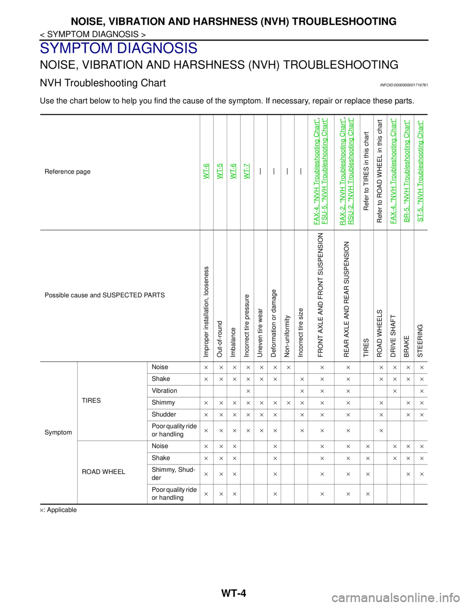
NVH Troubleshooting ChartINFOID:0000000001716761
Use the chart below to help you find the cause of the symptom. If necessary, repair or replace these parts.
×: ApplicableReference page
WT-6WT-5
WT-6
WT-7—
—
—
—
FA X - 4 , "
NVH Troubleshooting Chart
",
FSU-5, "
NVH Troubleshooting Chart
"
RAX-2, "
NVH Troubleshooting Chart
",
RSU-2, "
NVH Troubleshooting Chart
"
Refer to TIRES in this chart
Refer to ROAD WHEEL in this chart
FAX-4, "
NVH Troubleshooting Chart
"
BR-5, "
NVH Troubleshooting Chart
"
ST-5, "
NVH Troubleshooting Chart
"
Possible cause and SUSPECTED PARTS
Improper installation, looseness
Out-of-round
Imbalance
Incorrect tire pressure
Uneven tire wear
Deformation or damage
Non-uniformity
Incorrect tire size
FRONT AXLE AND FRONT SUSPENSION
REAR AXLE AND REAR SUSPENSION
TIRES
ROAD WHEELS
DRIVE SHAFT
BRAKE
STEERING
SymptomTIRESNoise× ×××××× × × ××××
Shake× ××××× × × × ××××
Vibration××××××
Shimmy× ××××××× × × × ××
Shudder× ××××× × × × × ××
Poor quality ride
or handling× ××××× × × × ×
ROAD WHEELNoise× ×× × × × × ×××
Shake× ×× × × × × ×××
Shimmy, Shud-
der×××× ×××××
Poor quality ride
or handling××× × × × ×
Page 5878 of 5883

WW-76
< ON-VEHICLE REPAIR >
WIPER AND WASHER SWITCH
WIPER AND WASHER SWITCH
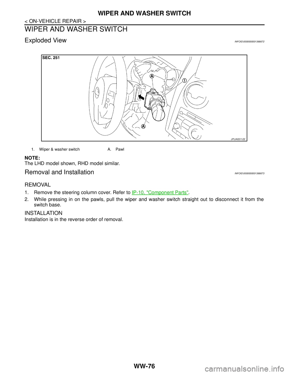
Exploded ViewINFOID:0000000001366672
NOTE:
The LHD model shown, RHD model similar.
Removal and InstallationINFOID:0000000001366673
REMOVAL
1. Remove the steering column cover. Refer to IP-10, "Component Parts".
2. While pressing in on the pawls, pull the wiper and washer switch straight out to disconnect it from the
switch base.
INSTALLATION
Installation is in the reverse order of removal.
1. Wiper & washer switch A. Pawl
JPLIA0311ZZ