time NISSAN TIIDA 2007 Service Repair Manual
[x] Cancel search | Manufacturer: NISSAN, Model Year: 2007, Model line: TIIDA, Model: NISSAN TIIDA 2007Pages: 5883, PDF Size: 78.95 MB
Page 5300 of 5883
TM-354
< FUNCTION DIAGNOSIS >[TYPE 2 (4AT: RE4F03B)]
DIAGNOSIS SYSTEM (TCM)
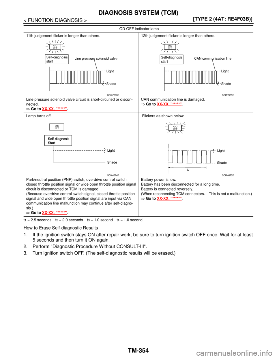
t1 = 2.5 seconds t2 = 2.0 seconds t3 = 1.0 second t4 = 1.0 second
How to Erase Self-diagnostic Results
1. If the ignition switch stays ON after repair work, be sure to turn ignition switch OFF once. Wait for at least
5 seconds and then turn it ON again.
2. Perform "Diagnostic Procedure Without CONSULT-III".
3. Turn ignition switch OFF. (The self-diagnostic results will be erased.)
11th judgement flicker is longer than others.
Line pressure solenoid valve circuit is short-circuited or discon-
nected.
⇒ Go to XX-XX, "*****"
.12th judgement flicker is longer than others.
CAN communication line is damaged.
⇒ Go to XX-XX, "*****"
.
Lamp turns off.
Park/neutral position (PNP) switch, overdrive control switch,
closed throttle position signal or wide open throttle position signal
circuit is disconnected or TCM is damaged.
(Because overdrive control switch signal, closed throttle position
signal and wide open throttle position signal are input via CAN
communication line malfunction may continue after self-diagno-
sis.)
⇒ Go to XX-XX, "*****"
. Flickers as shown below.
Battery power is low.
Battery has been disconnected for a long time.
Battery is connected reversely.
(When reconnecting TCM connectors.—This is not a malfunction.)
⇒ Go to XX-XX, "*****"
. OD OFF indicator lamp
SCIA7083ESCIA7085E
SCIA4674ESCIA4675E
Page 5337 of 5883
CAN COMMUNICATION LINE
TM-391
< COMPONENT DIAGNOSIS >[TYPE 2 (4AT: RE4F03B)]
C
E
F
G
H
I
J
K
L
MA
B
TM
N
O
P
CAN COMMUNICATION LINE
DescriptionINFOID:0000000001713064
CAN (Controller Area Network) is a serial communication line for real time application. It is an on-vehicle mul-
tiplex communication line with high data communication speed and excellent malfunction detection ability.
Many electronic control units are equipped onto a vehicle, and each control unit shares information and links
with other control units during operation (not independent). In CAN communication, control units are con-
nected with 2 communication lines (CAN H line, CAN L line) allowing a high rate of information transmission
with less wiring. Each control unit transmits/receives data but selectively reads required data only.
On Board Diagnosis LogicINFOID:0000000001713065
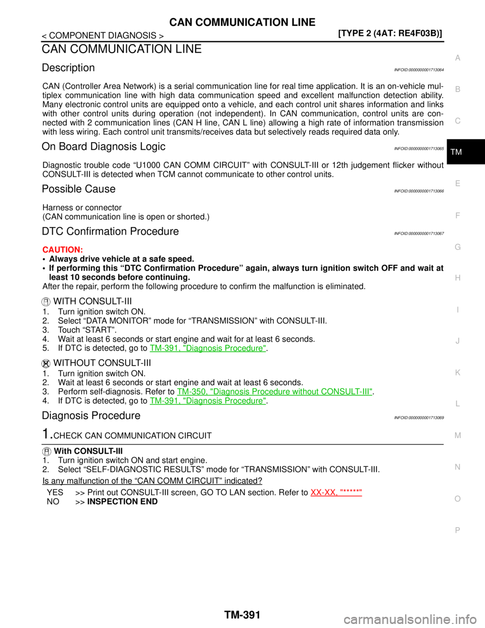
Diagnostic trouble code “U1000 CAN COMM CIRCUIT” with CONSULT-III or 12th judgement flicker without
CONSULT-III is detected when TCM cannot communicate to other control units.
Possible CauseINFOID:0000000001713066
Harness or connector
(CAN communication line is open or shorted.)
DTC Confirmation ProcedureINFOID:0000000001713067
CAUTION:
Always drive vehicle at a safe speed.
If performing this “DTC Confirmation Procedure” again, always turn ignition switch OFF and wait at
least 10 seconds before continuing.
After the repair, perform the following procedure to confirm the malfunction is eliminated.
WITH CONSULT-III
1. Turn ignition switch ON.
2. Select “DATA MONITOR” mode for “TRANSMISSION” with CONSULT-III.
3. Touch “START”.
4. Wait at least 6 seconds or start engine and wait for at least 6 seconds.
5. If DTC is detected, go to TM-391, "
Diagnosis Procedure".
WITHOUT CONSULT-III
1. Turn ignition switch ON.
2. Wait at least 6 seconds or start engine and wait at least 6 seconds.
3. Perform self-diagnosis. Refer to TM-350, "
Diagnosis Procedure without CONSULT-III".
4. If DTC is detected, go to TM-391, "
Diagnosis Procedure".
Diagnosis ProcedureINFOID:0000000001713069
1.CHECK CAN COMMUNICATION CIRCUIT
With CONSULT-III
1. Turn ignition switch ON and start engine.
2. Select “SELF-DIAGNOSTIC RESULTS” mode for “TRANSMISSION” with CONSULT-III.
Is any malfunction of the
“CAN COMM CIRCUIT” indicated?
YES >> Print out CONSULT-III screen, GO TO LAN section. Refer to XX-XX, "*****"
NO >>INSPECTION END
Page 5341 of 5883
A/T 1ST GEAR FUNCTION
TM-395
< COMPONENT DIAGNOSIS >[TYPE 2 (4AT: RE4F03B)]
C
E
F
G
H
I
J
K
L
MA
B
TM
N
O
P
THROTTLE POSI: Less than 1.0/8 (at all times during step 4)
SLCT LVR POSI: “D” position
-Make sure that “GEAR” shows “2” after releasing pedal.
6. Depress accelerator pedal to WOT (more than 7.0/8 of “THROTTLE POSI”) quickly from a speed of 20 to
25 km/h (12 to 16 MPH) until “TESTING” changes to “STOP VEHICLE” or “COMPLETED”. (It will take
approximately 3 seconds.)
If the check result NG appears on CONSULT-III screen, go to TM-395, "
Diagnosis Procedure".
If “STOP VEHICLE” appears on CONSULT-III screen, go to the following step.
-Make sure that “GEAR” shows “1” when depressing accelerator pedal to WOT.
-If “TESTING” does not appear on CONSULT-III for a long time, select “SELF-DIAGNOSTIC
RESULTS” for “TRANSMISSION”. In case a DTC other than “A/T 1ST GR FNCTN” is shown, refer
to XX-XX, "*****"
.
7. Stop vehicle.
8. Follow the instruction displayed. (Check for normal shifting referring to the table below.)
9. Make sure that “OK” is displayed. (If “NG” is displayed, refer to “Diagnostic Procedure”.)
Refer to TM-395, "
Diagnosis Procedure".
Refer to XX-XX, "*****"
.
Diagnosis ProcedureINFOID:0000000001713080
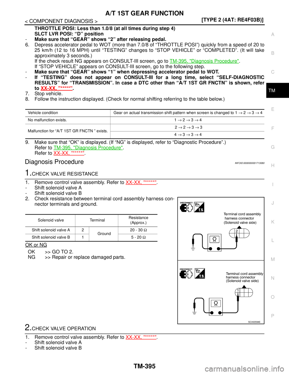
1.CHECK VALVE RESISTANCE
1. Remove control valve assembly. Refer to XX-XX, "*****"
.
- Shift solenoid valve A
- Shift solenoid valve B
2. Check resistance between terminal cord assembly harness con-
nector terminals and ground.
OK or NG
OK >> GO TO 2.
NG >> Repair or replace damaged parts.
2.CHECK VALVE OPERATION
1. Remove control valve assembly. Refer to XX-XX, "*****"
.
- Shift solenoid valve A
- Shift solenoid valve B
Vehicle condition Gear on actual transmission shift pattern when screen is changed to 1 → 2 → 3 → 4
No malfunction exists. 1 → 2 → 3 → 4
Malfunction for “A/T 1ST GR FNCTN ” exists. 2 → 2 → 3 → 3
4 → 3 → 3 → 4
Solenoid valve TerminalResistance
(Approx.)
Shift solenoid valve A 2
Ground20 - 30 Ω
Shift solenoid valve B 1 5 - 20 Ω
SCIA3594E
Page 5344 of 5883
TM-398
< COMPONENT DIAGNOSIS >[TYPE 2 (4AT: RE4F03B)]
A/T 2ND GEAR FUNCTION
6. Depress accelerator pedal to WOT (more than 7.0/8 of “THROTTLE POSI”) quickly from a speed of 45 to
50 km/h (28 to 31 MPH) until “TESTING” changes to “STOP VEHICLE” or “COMPLETE”. (It will take
approximately 3 seconds.)
If the check result NG appears on CONSULT-III screen, go to TM-398, "
Diagnosis Procedure".
If “STOP VEHICLE” appears on CONSULT-III screen, go to following step.
-Make sure that “GEAR” shows “2” when depressing accelerator pedal to WOT.
-If “TESTING” does not appear on CONSULT-III for a long time, select “SELF-DIAGNOSTIC
RESULTS” for “TRANSMISSION”. In case a DTC other than “A/T 2ND GR FNCTN” is shown, refer
to XX-XX, "*****"
.
7. Stop vehicle.
8. Follow the instruction displayed. (Check for normal shifting referring to the table below.)
9. Make sure that “OK” is displayed. (If “NG” is displayed, refer to “Diagnostic Procedure”.)
Refer to TM-398, "
Diagnosis Procedure".
Refer to XX-XX, "*****"
.
Diagnosis ProcedureINFOID:0000000001713085
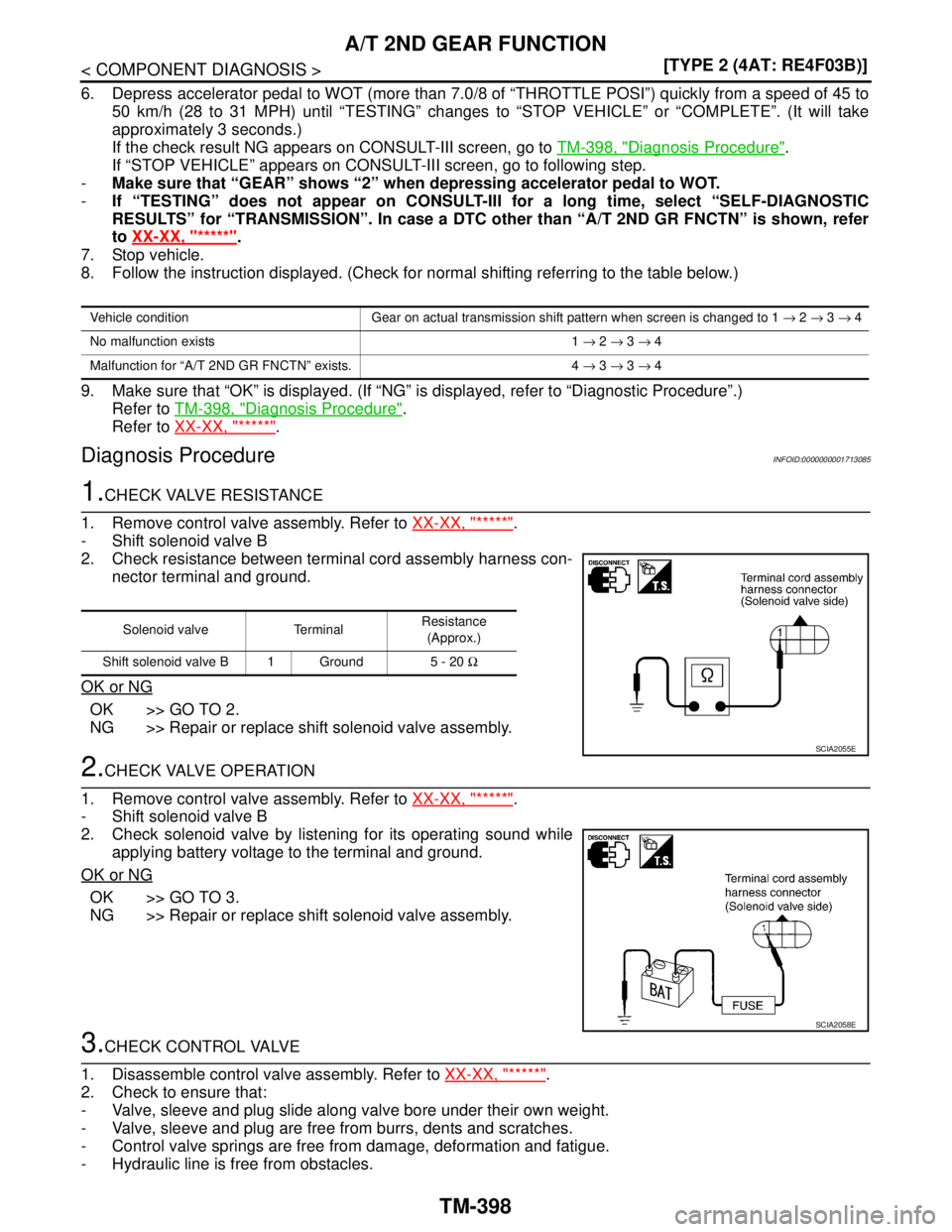
1.CHECK VALVE RESISTANCE
1. Remove control valve assembly. Refer to XX-XX, "*****"
.
- Shift solenoid valve B
2. Check resistance between terminal cord assembly harness con-
nector terminal and ground.
OK or NG
OK >> GO TO 2.
NG >> Repair or replace shift solenoid valve assembly.
2.CHECK VALVE OPERATION
1. Remove control valve assembly. Refer to XX-XX, "*****"
.
- Shift solenoid valve B
2. Check solenoid valve by listening for its operating sound while
applying battery voltage to the terminal and ground.
OK or NG
OK >> GO TO 3.
NG >> Repair or replace shift solenoid valve assembly.
3.CHECK CONTROL VALVE
1. Disassemble control valve assembly. Refer to XX-XX, "*****"
.
2. Check to ensure that:
- Valve, sleeve and plug slide along valve bore under their own weight.
- Valve, sleeve and plug are free from burrs, dents and scratches.
- Control valve springs are free from damage, deformation and fatigue.
- Hydraulic line is free from obstacles.
Vehicle condition Gear on actual transmission shift pattern when screen is changed to 1 → 2 → 3 → 4
No malfunction exists 1 → 2 → 3 → 4
Malfunction for “A/T 2ND GR FNCTN” exists. 4 → 3 → 3 → 4
Solenoid valve TerminalResistance
(Approx.)
Shift solenoid valve B 1 Ground 5 - 20 Ω
SCIA2055E
SCIA2058E
Page 5346 of 5883
TM-400
< COMPONENT DIAGNOSIS >[TYPE 2 (4AT: RE4F03B)]
A/T 3RD GEAR FUNCTION
A/T 3RD GEAR FUNCTION
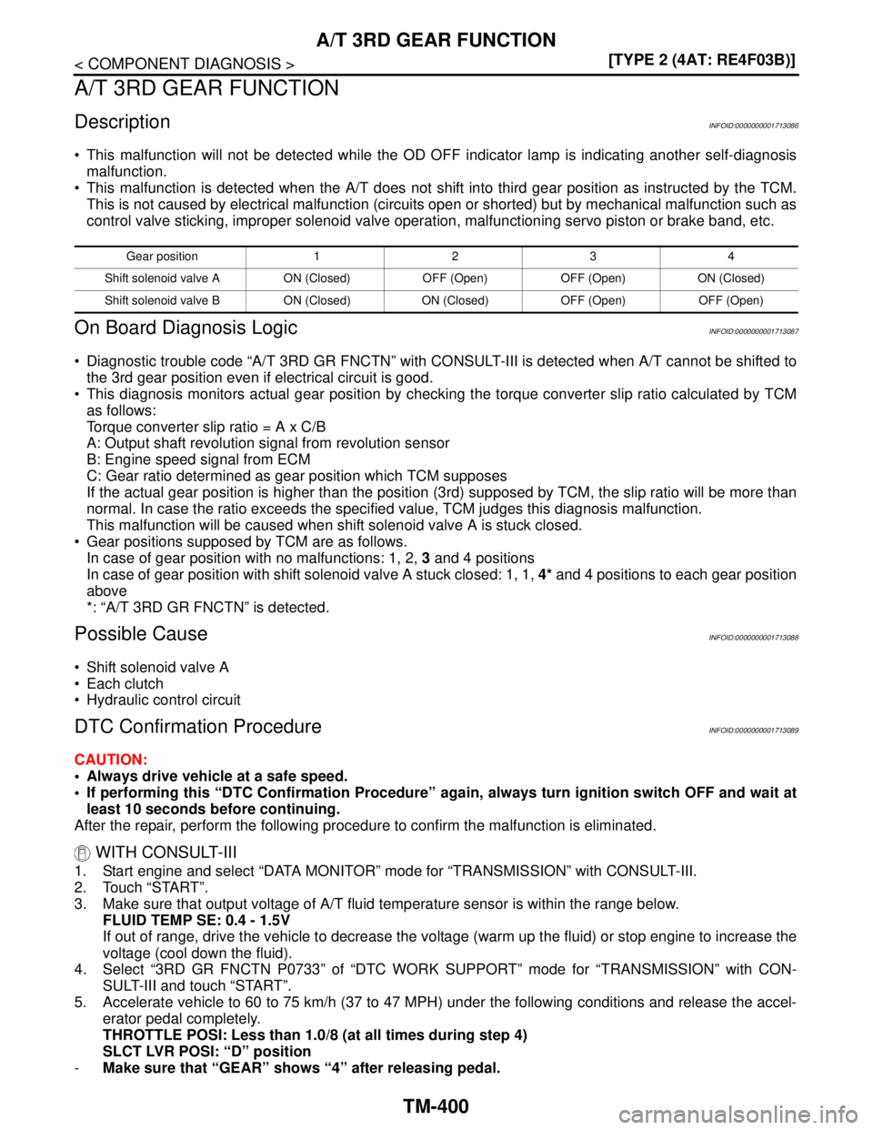
DescriptionINFOID:0000000001713086
This malfunction will not be detected while the OD OFF indicator lamp is indicating another self-diagnosis
malfunction.
This malfunction is detected when the A/T does not shift into third gear position as instructed by the TCM.
This is not caused by electrical malfunction (circuits open or shorted) but by mechanical malfunction such as
control valve sticking, improper solenoid valve operation, malfunctioning servo piston or brake band, etc.
On Board Diagnosis LogicINFOID:0000000001713087
Diagnostic trouble code “A/T 3RD GR FNCTN” with CONSULT-III is detected when A/T cannot be shifted to
the 3rd gear position even if electrical circuit is good.
This diagnosis monitors actual gear position by checking the torque converter slip ratio calculated by TCM
as follows:
Torque converter slip ratio = A x C/B
A: Output shaft revolution signal from revolution sensor
B: Engine speed signal from ECM
C: Gear ratio determined as gear position which TCM supposes
If the actual gear position is higher than the position (3rd) supposed by TCM, the slip ratio will be more than
normal. In case the ratio exceeds the specified value, TCM judges this diagnosis malfunction.
This malfunction will be caused when shift solenoid valve A is stuck closed.
Gear positions supposed by TCM are as follows.
In case of gear position with no malfunctions: 1, 2, 3 and 4 positions
In case of gear position with shift solenoid valve A stuck closed: 1, 1, 4* and 4 positions to each gear position
above
*: “A/T 3RD GR FNCTN” is detected.
Possible CauseINFOID:0000000001713088
Shift solenoid valve A
Each clutch
Hydraulic control circuit
DTC Confirmation ProcedureINFOID:0000000001713089
CAUTION:
Always drive vehicle at a safe speed.
If performing this “DTC Confirmation Procedure” again, always turn ignition switch OFF and wait at
least 10 seconds before continuing.
After the repair, perform the following procedure to confirm the malfunction is eliminated.
WITH CONSULT-III
1. Start engine and select “DATA MONITOR” mode for “TRANSMISSION” with CONSULT-III.
2. Touch “START”.
3. Make sure that output voltage of A/T fluid temperature sensor is within the range below.
FLUID TEMP SE: 0.4 - 1.5V
If out of range, drive the vehicle to decrease the voltage (warm up the fluid) or stop engine to increase the
voltage (cool down the fluid).
4. Select “3RD GR FNCTN P0733” of “DTC WORK SUPPORT” mode for “TRANSMISSION” with CON-
SULT-III and touch “START”.
5. Accelerate vehicle to 60 to 75 km/h (37 to 47 MPH) under the following conditions and release the accel-
erator pedal completely.
THROTTLE POSI: Less than 1.0/8 (at all times during step 4)
SLCT LVR POSI: “D” position
-Make sure that “GEAR” shows “4” after releasing pedal.
Gear position1234
Shift solenoid valve A ON (Closed) OFF (Open) OFF (Open) ON (Closed)
Shift solenoid valve B ON (Closed) ON (Closed) OFF (Open) OFF (Open)
Page 5347 of 5883
A/T 3RD GEAR FUNCTION
TM-401
< COMPONENT DIAGNOSIS >[TYPE 2 (4AT: RE4F03B)]
C
E
F
G
H
I
J
K
L
MA
B
TM
N
O
P
6. Depress accelerator pedal steadily with 3.5/8 - 4.5/8 of “THROTTLE POSI” from a speed of 60 to 75 km/h
(37 to 47 MPH) until “TESTING” changes to “STOP VEHICLE” or “COMPLETED”. (It will take approxi-
mately 3 seconds.)
If the check result NG appears on CONSULT-III screen, go to TM-401, "
Diagnosis Procedure".
If “STOP VEHICLE” appears on CONSULT-III screen, go to following step.
-Make sure that “GEAR” shows “3” when depressing accelerator pedal with 3.5/8 - 4.5/8 of
“THROTTLE POSI”.
-If “TESTING” does not appear on CONSULT-III for a long time, select “SELF-DIAG RESULTS” for
“TRANSMISSION”. In case a DTC other than “A/T 3RD GR FNCTN” is shown, refer to XX-XX,
"*****".
7. Stop vehicle.
8. Follow the instruction displayed. (Check for normal shifting referring to the table below.)
9. Make sure that “OK” is displayed. (If “NG” is displayed, refer to “Diagnostic Procedure”.)
Refer to TM-401, "
Diagnosis Procedure".
Refer to XX-XX, "*****"
.
Diagnosis ProcedureINFOID:0000000001713090
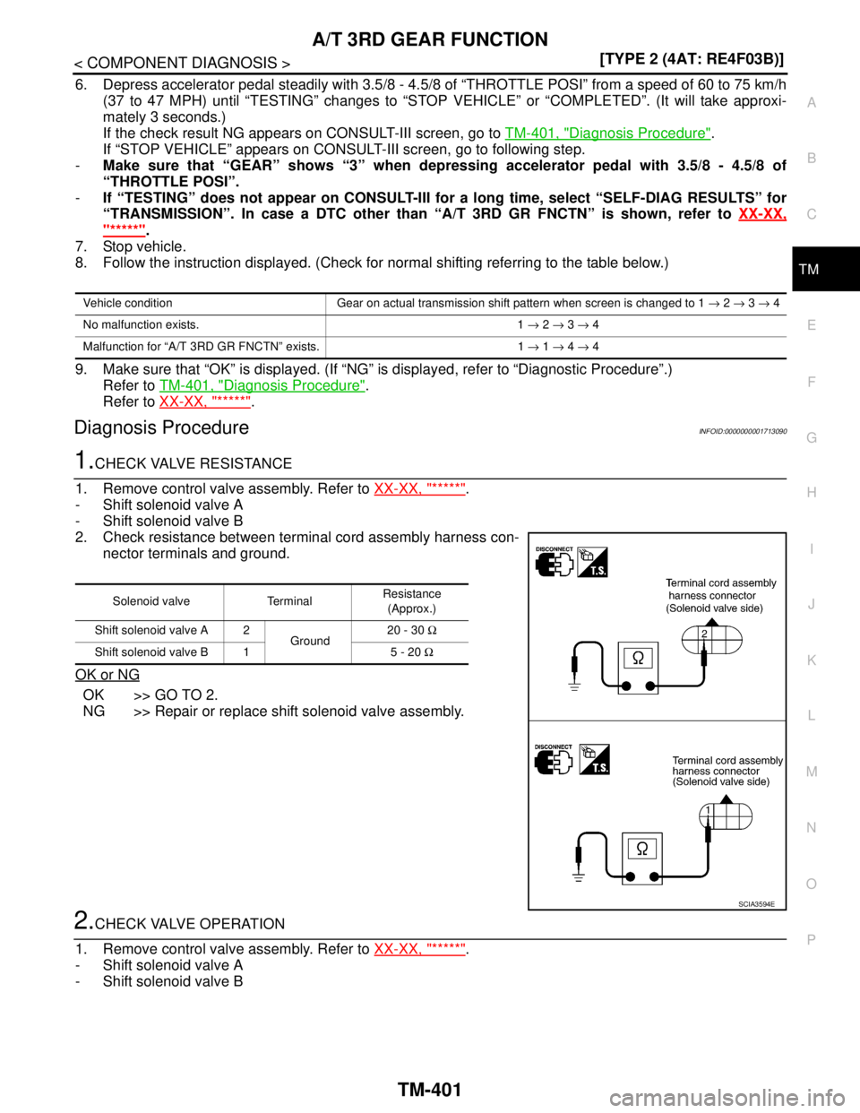
1.CHECK VALVE RESISTANCE
1. Remove control valve assembly. Refer to XX-XX, "*****"
.
- Shift solenoid valve A
- Shift solenoid valve B
2. Check resistance between terminal cord assembly harness con-
nector terminals and ground.
OK or NG
OK >> GO TO 2.
NG >> Repair or replace shift solenoid valve assembly.
2.CHECK VALVE OPERATION
1. Remove control valve assembly. Refer to XX-XX, "*****"
.
- Shift solenoid valve A
- Shift solenoid valve B
Vehicle condition Gear on actual transmission shift pattern when screen is changed to 1 → 2 → 3 → 4
No malfunction exists. 1 → 2 → 3 → 4
Malfunction for “A/T 3RD GR FNCTN” exists. 1 → 1 → 4 → 4
Solenoid valve TerminalResistance
(Approx.)
Shift solenoid valve A 2
Ground20 - 30 Ω
Shift solenoid valve B 1 5 - 20 Ω
SCIA3594E
Page 5350 of 5883
TM-404
< COMPONENT DIAGNOSIS >[TYPE 2 (4AT: RE4F03B)]
A/T 4TH GEAR FUNCTION
3. Make sure that output voltage of A/T fluid temperature sensor is within the range below.
FLUID TEMP SE: 0.4 - 1.5V
If out of range, drive the vehicle to decrease the voltage (warm up the fluid) or stop engine to increase the
voltage (cool down the fluid).
4. Select “4TH GR FNCTN P0734” of “DTC WORK SUPPORT” mode for “TRANSMISSION” with CON-
SULT-III and touch “START”.
5. Accelerate vehicle to 55 to 65 km/h (34 to 40 MPH) under the following conditions and release the accel-
erator pedal completely.
THROTTLE POSI: Less than 5.5/8 (at all times during step 4)
SLCT LVR POSI: “D” position
-Make sure that “GEAR” shows “3” after releasing pedal.
6. Depress accelerator pedal steadily with 1.0/8 - 2.0/8 of “THROTTLE POSI” from a speed of 55 to 65 km/h
(34 to 40 MPH) until “TESTING” has turned to “STOP VEHICLE” or “COMPLETED”. (It will take approxi-
mately 3 seconds.)
If the check result NG appears on CONSULT-III screen, go to TM-404, "
Diagnosis Procedure".
If “STOP VEHICLE” appears on CONSULT-III screen, go to following step.
-Make sure that “GEAR” shows “4” when depressing accelerator pedal with 1.0/8 - 2.0/8 of
“THROTTLE POSI”.
-If “TESTING” does not appear on CONSULT-III for a long time, select “SELF-DIAG RESULTS” for
“A/T”. In case a DTC other than “A/T 4TH GR FNCTN” is shown, refer to XX-XX, "*****"
.
7. Stop vehicle.
8. Follow the instruction displayed. (Check for normal shifting referring to the table below.)
9. Make sure that “OK” is displayed. (If “NG” is displayed, refer to “Diagnostic Procedure”.)
Refer to TM-404, "
Diagnosis Procedure".
Refer to XX-XX, "*****"
.
Diagnosis ProcedureINFOID:0000000001713095
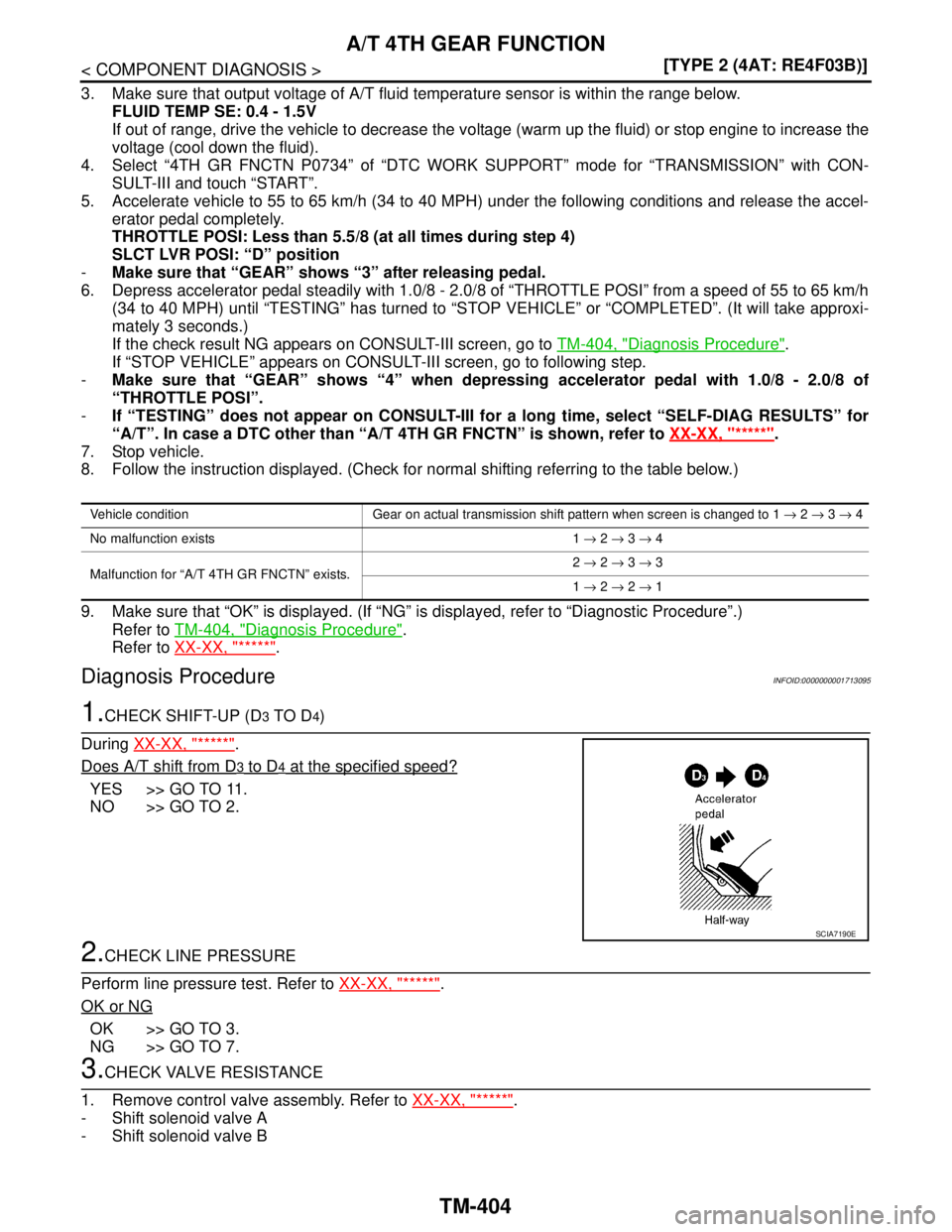
1.CHECK SHIFT-UP (D3 TO D4)
During XX-XX, "*****"
.
Does A/T shift from D
3 to D4 at the specified speed?
YES >> GO TO 11.
NO >> GO TO 2.
2.CHECK LINE PRESSURE
Perform line pressure test. Refer to XX-XX, "*****"
.
OK or NG
OK >> GO TO 3.
NG >> GO TO 7.
3.CHECK VALVE RESISTANCE
1. Remove control valve assembly. Refer to XX-XX, "*****"
.
- Shift solenoid valve A
- Shift solenoid valve B
Vehicle condition Gear on actual transmission shift pattern when screen is changed to 1 → 2 → 3 → 4
No malfunction exists 1 → 2 → 3 → 4
Malfunction for “A/T 4TH GR FNCTN” exists.2 → 2 → 3 → 3
1 → 2 → 2 → 1
SCIA7190E
Page 5355 of 5883
A/T TCC S/V FUNCTION (LOCK-UP)
TM-409
< COMPONENT DIAGNOSIS >[TYPE 2 (4AT: RE4F03B)]
C
E
F
G
H
I
J
K
L
MA
B
TM
N
O
P
5. Accelerate vehicle to more than 80 km/h (50 MPH) and maintain the following conditions continuously
until “TESTING” has turned to “COMPLETE”. (It will take approximately 30 seconds after “TESTING”
shows.)
THROTTLE POSI: 1.0/8 - 2.0/8 (at all times during step 4)
SLCT LVR POSI: “D” position
TCC S/V DUTY: More than 94%
VEHICLE SPEED: Constant speed of more than 80 km/h (50 MPH)
-Make sure that “GEAR” shows “4”.
-For shift schedule, refer to XX-XX, "*****"
.
-If “TESTING” does not appear on CONSULT-III for a long time, select “SELF-DIAG RESULTS”. In
case a DTC other than “A/T TCC S/V FNCTN” is shown, refer to XX-XX, "*****"
.
6. Make sure that “OK” is displayed. (If “NG” is displayed, refer to “DIAGNOSTIC PROCEDURE”.)
Refer to TM-409, "
Diagnosis Procedure".
Refer to XX-XX, "*****"
.
Diagnosis ProcedureINFOID:0000000001713101
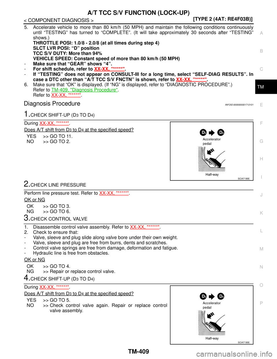
1.CHECK SHIFT-UP (D3 TO D4)
During XX-XX, "*****"
.
Does A/T shift from D
3 to D4 at the specified speed?
YES >> GO TO 11.
NO >> GO TO 2.
2.CHECK LINE PRESSURE
Perform line pressure test. Refer to XX-XX, "*****"
.
OK or NG
OK >> GO TO 3.
NG >> GO TO 6.
3.CHECK CONTROL VALVE
1. Disassemble control valve assembly. Refer to XX-XX, "*****"
.
2. Check to ensure that:
- Valve, sleeve and plug slide along valve bore under their own weight.
- Valve, sleeve and plug are free from burrs, dents and scratches.
- Control valve springs are free from damage, deformation and fatigue.
- Hydraulic line is free from obstacles.
OK or NG
OK >> GO TO 4.
NG >> Repair or replace control valve.
4.CHECK SHIFT-UP (D3 TO D4)
During XX-XX, "*****"
.
Does A/T shift from D
3 to D4 at the specified speed?
YES >> GO TO 5.
NO >> Check control valve again. Repair or replace control
valve assembly.
SCIA7190E
SCIA7190E
Page 5368 of 5883
TM-422
< ECU DIAGNOSIS >[TYPE 2 (4AT: RE4F03B)]
TCM
ECU DIAGNOSIS
TCM
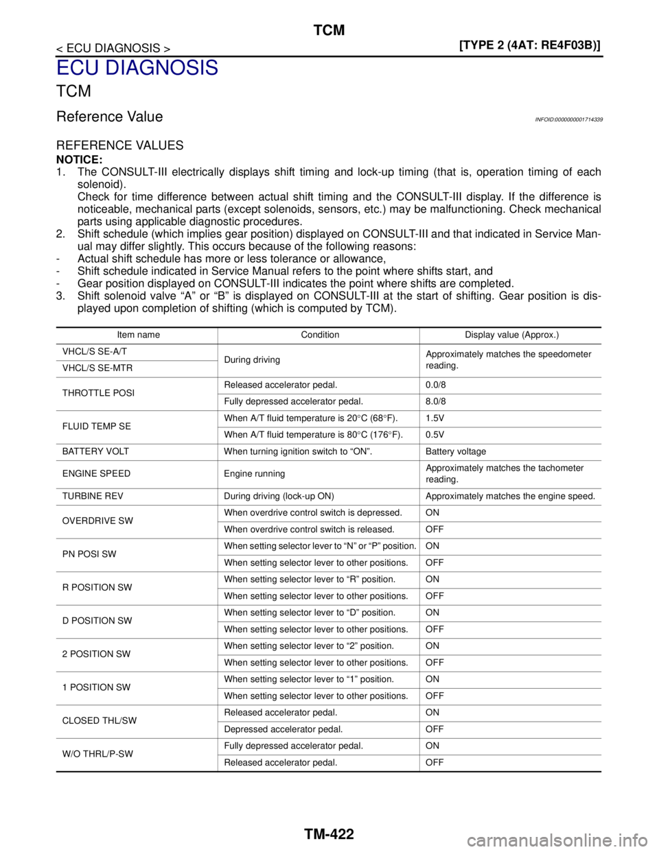
Reference ValueINFOID:0000000001714339
REFERENCE VALUES
NOTICE:
1. The CONSULT-III electrically displays shift timing and lock-up timing (that is, operation timing of each
solenoid).
Check for time difference between actual shift timing and the CONSULT-III display. If the difference is
noticeable, mechanical parts (except solenoids, sensors, etc.) may be malfunctioning. Check mechanical
parts using applicable diagnostic procedures.
2. Shift schedule (which implies gear position) displayed on CONSULT-III and that indicated in Service Man-
ual may differ slightly. This occurs because of the following reasons:
- Actual shift schedule has more or less tolerance or allowance,
- Shift schedule indicated in Service Manual refers to the point where shifts start, and
- Gear position displayed on CONSULT-III indicates the point where shifts are completed.
3. Shift solenoid valve “A” or “B” is displayed on CONSULT-III at the start of shifting. Gear position is dis-
played upon completion of shifting (which is computed by TCM).
Item name Condition Display value (Approx.)
VHCL/S SE-A/T
During drivingApproximately matches the speedometer
reading.
VHCL/S SE-MTR
THROTTLE POSIReleased accelerator pedal. 0.0/8
Fully depressed accelerator pedal. 8.0/8
FLUID TEMP SE When A/T fluid temperature is 20°C (68°F). 1.5V
When A/T fluid temperature is 80°C (176°F). 0.5V
BATTERY VOLT When turning ignition switch to “ON”. Battery voltage
ENGINE SPEED Engine runningApproximately matches the tachometer
reading.
TURBINE REV During driving (lock-up ON) Approximately matches the engine speed.
OVERDRIVE SWWhen overdrive control switch is depressed. ON
When overdrive control switch is released. OFF
PN POSI SWWhen setting selector lever to “N” or “P” position. ON
When setting selector lever to other positions. OFF
R POSITION SWWhen setting selector lever to “R” position. ON
When setting selector lever to other positions. OFF
D POSITION SWWhen setting selector lever to “D” position. ON
When setting selector lever to other positions. OFF
2 POSITION SWWhen setting selector lever to “2” position. ON
When setting selector lever to other positions. OFF
1 POSITION SWWhen setting selector lever to “1” position. ON
When setting selector lever to other positions. OFF
CLOSED THL/SWReleased accelerator pedal. ON
Depressed accelerator pedal. OFF
W/O THRL/P-SWFully depressed accelerator pedal. ON
Released accelerator pedal. OFF
Page 5411 of 5883
PRECAUTIONS
TM-465
< PRECAUTION >[TYPE 2 (4AT: RE4F03B)]
C
E
F
G
H
I
J
K
L
MA
B
TM
N
O
P
PRECAUTION
PRECAUTIONS
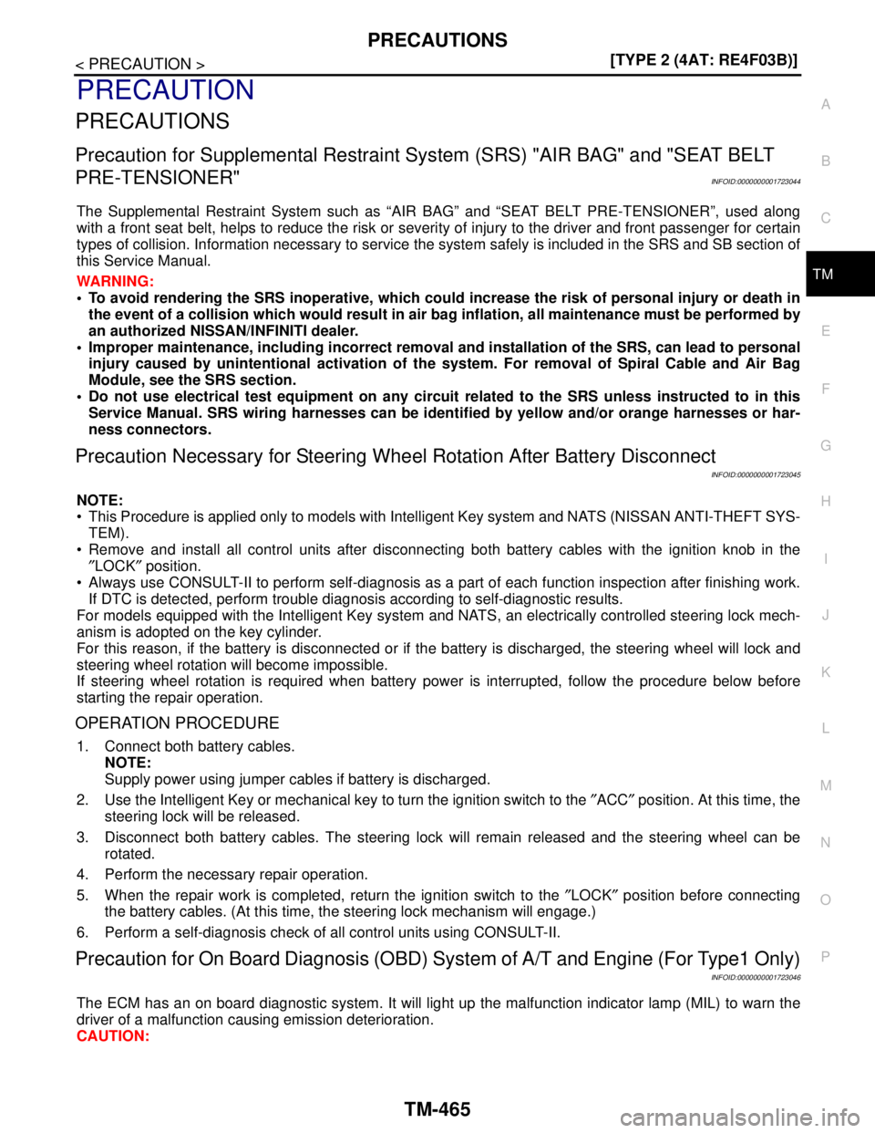
Precaution for Supplemental Restraint System (SRS) "AIR BAG" and "SEAT BELT
PRE-TENSIONER"
INFOID:0000000001723044
The Supplemental Restraint System such as “AIR BAG” and “SEAT BELT PRE-TENSIONER”, used along
with a front seat belt, helps to reduce the risk or severity of injury to the driver and front passenger for certain
types of collision. Information necessary to service the system safely is included in the SRS and SB section of
this Service Manual.
WARNING:
To avoid rendering the SRS inoperative, which could increase the risk of personal injury or death in
the event of a collision which would result in air bag inflation, all maintenance must be performed by
an authorized NISSAN/INFINITI dealer.
Improper maintenance, including incorrect removal and installation of the SRS, can lead to personal
injury caused by unintentional activation of the system. For removal of Spiral Cable and Air Bag
Module, see the SRS section.
Do not use electrical test equipment on any circuit related to the SRS unless instructed to in this
Service Manual. SRS wiring harnesses can be identified by yellow and/or orange harnesses or har-
ness connectors.
Precaution Necessary for Steering Wheel Rotation After Battery Disconnect
INFOID:0000000001723045
NOTE:
This Procedure is applied only to models with Intelligent Key system and NATS (NISSAN ANTI-THEFT SYS-
TEM).
Remove and install all control units after disconnecting both battery cables with the ignition knob in the
″LOCK″ position.
Always use CONSULT-II to perform self-diagnosis as a part of each function inspection after finishing work.
If DTC is detected, perform trouble diagnosis according to self-diagnostic results.
For models equipped with the Intelligent Key system and NATS, an electrically controlled steering lock mech-
anism is adopted on the key cylinder.
For this reason, if the battery is disconnected or if the battery is discharged, the steering wheel will lock and
steering wheel rotation will become impossible.
If steering wheel rotation is required when battery power is interrupted, follow the procedure below before
starting the repair operation.
OPERATION PROCEDURE
1. Connect both battery cables.
NOTE:
Supply power using jumper cables if battery is discharged.
2. Use the Intelligent Key or mechanical key to turn the ignition switch to the ″ACC″ position. At this time, the
steering lock will be released.
3. Disconnect both battery cables. The steering lock will remain released and the steering wheel can be
rotated.
4. Perform the necessary repair operation.
5. When the repair work is completed, return the ignition switch to the ″LOCK″ position before connecting
the battery cables. (At this time, the steering lock mechanism will engage.)
6. Perform a self-diagnosis check of all control units using CONSULT-II.
Precaution for On Board Diagnosis (OBD) System of A/T and Engine (For Type1 Only)
INFOID:0000000001723046
The ECM has an on board diagnostic system. It will light up the malfunction indicator lamp (MIL) to warn the
driver of a malfunction causing emission deterioration.
CAUTION: