check engine light NISSAN TIIDA 2007 Service Workshop Manual
[x] Cancel search | Manufacturer: NISSAN, Model Year: 2007, Model line: TIIDA, Model: NISSAN TIIDA 2007Pages: 5883, PDF Size: 78.95 MB
Page 2384 of 5883
FUEL PRESSURE
EC-1035
< ON-VEHICLE REPAIR >[MR18DE]
C
D
E
F
G
H
I
J
K
L
MA
EC
N
P O
ON-VEHICLE REPAIR
FUEL PRESSURE
InspectionINFOID:0000000001162005
FUEL PRESSURE RELEASE
With CONSULT-III
1. Turn ignition switch ON.
2. Perform “FUEL PRESSURE RELEASE” in “WORK SUPPORT” mode with CONSULT-III.
3. Start engine.
4. After engine stalls, crank it two or three times to release all fuel pressure.
5. Turn ignition switch OFF.
With CONSULT-III
1. Remove fuel pump fuse located in IPDM E/R.
2. Start engine.
3. After engine stalls, crank it two or three times to release all fuel pressure.
4. Turn ignition switch OFF.
5. Reinstall fuel pump fuse after servicing fuel system.
FUEL PRESSURE CHECK
CAUTION:
Before disconnecting fuel line, release fuel pressure from fuel line to eliminate danger.
The fuel hose connection method used when taking fuel pressure check must not be used for other
purposes.
Be careful not to scratch or put debris around connection area when servicing, so that the quick
connector maintains sealability with O-rings inside.
Do not perform fuel pressure check with electrical systems operating (i.e. lights, rear defogger, A/C,
etc.) Fuel pressure gauge may indicate false readings due to varying engine load and changes in
manifold vacuum.
NOTE:
Prepare pans or saucers under the disconnected fuel line because the fuel may spill out. The fuel pres-
sure cannot be completely released because C11 models do not have fuel return system.
1. Release fuel pressure to zero.
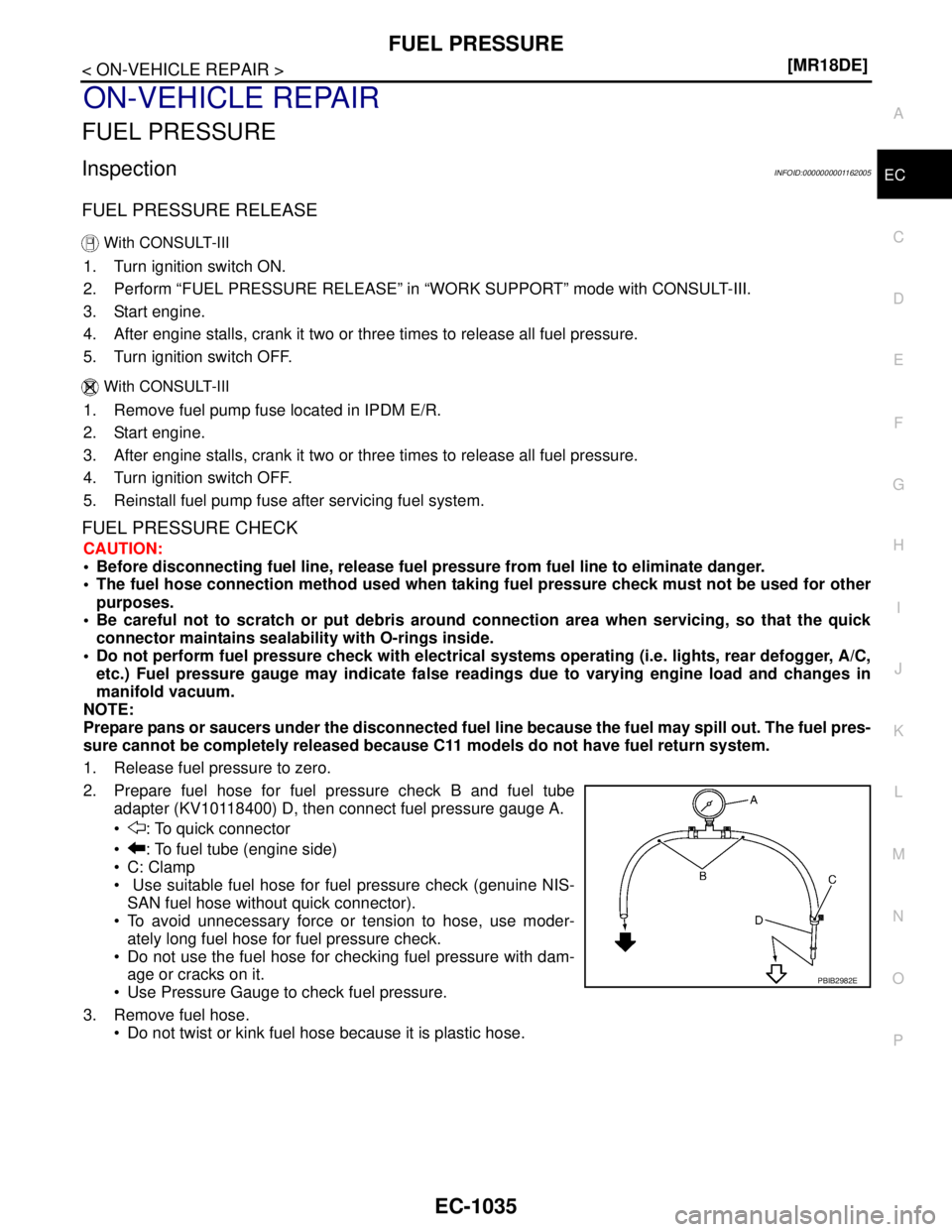
2. Prepare fuel hose for fuel pressure check B and fuel tube
adapter (KV10118400) D, then connect fuel pressure gauge A.
: To quick connector
: To fuel tube (engine side)
C: Clamp
Use suitable fuel hose for fuel pressure check (genuine NIS-
SAN fuel hose without quick connector).
To avoid unnecessary force or tension to hose, use moder-
ately long fuel hose for fuel pressure check.
Do not use the fuel hose for checking fuel pressure with dam-
age or cracks on it.
Use Pressure Gauge to check fuel pressure.
3. Remove fuel hose.
Do not twist or kink fuel hose because it is plastic hose.
PBIB2982E
Page 2453 of 5883
EC-1104
< FUNCTION DIAGNOSIS >[K9K]
ON BOARD DIAGNOSTIC (OBD) SYSTEM
ON BOARD DIAGNOSTIC (OBD) SYSTEM
Diagnosis DescriptionINFOID:0000000001162547
The ECM controls the display on the instrument panel of certain information relating to the operation of the
engine.
Four functions are involved here: The OBD malfunction indicator [MI (Yellow)] for the EOBD (European On
Board Diagnostics), the pre/post heating, the engine coolant temperature and engine malfunction [MI (Red)].
These four functions are represented by four lights given out by the ECM
GLOW LAMP
This lamp indicates that the glow control system has been activated.
ENGINE COOLANT TEMPERATURE LIGHT
This light is used as an indicator of engine overheating.
In the event of overheating, it is up to the driver whether to stop the vehicle or not.
MALFUNCTION INDICATOR
The OBD malfunction indicator [MI (Yellow)] is used to alert the driver to the existence of engine control sys-
tem malfunctions involving excessive pollution or if the EOBD system is deactivated.
The ECM makes a request for lighting of the MI (Yellow) only where there is a malfunction present at the end
of three consecutive cycles.
The 3-second visual check upon powering up (automatic test procedure controlled by the IPDM E/R) is per-
formed by the ECM.
In the event of a confirmed OBD malfunction by lighting of the MI, no flashing of the light must be observed fol-
lowing the lighting test.
DTCs Causing MI to Light
ENGINE WARNING LIGHT
In the event of an engine malfunction, the ECM may request the display of an engine warning light [MI (Red)].
HOW TO ERASE DTC, 1ST TRIP DTC AND 2ND TRIP DTC
With CONSULT-III
The emission related diagnostic information in the ECM can be erased by selecting “ALL ERASE” in the
“Description” of “FINAL CHECK” mode with CONSULT-III.
MI OPERATION CHART
Some malfunction must switch on MI to warn driver, that his engine emissions exceed OBD thresholds (Euro 3
x 2.5).
The rule is to switch on MI after 3 consecutive driving cycles (engine start + engine stop + power latch) with a
present OBD malfunction.
To switch off the MI (without CONSULT-III), vehicle has to drive 3 consecutive cycles without present OBD
malfunction.
Ignition switch OFF → ON transition, MI remains switched on in pre-drive check mode until engine start.If MI
does not switch off whereas engine is running, there is at least one present OBD malfunction.
DTC Description Reference page
P0201 Cylinder 1 fuel injector control circuitEC-1142
P0202 Cylinder 2 fuel injector control circuitEC-1142
P0203 Cylinder 3 fuel injector control circuitEC-1142
P0204 Cylinder 4 fuel injector control circuitEC-1142
P0409 EGR Volume control valve control position sensor circuitEC-1158
P0606 ECMEC-1178
P2413 EGR volume control valveEC-1202
Page 2458 of 5883
P0001 FUEL PUMP
EC-1109
< COMPONENT DIAGNOSIS >[K9K]
C
D
E
F
G
H
I
J
K
L
MA
EC
N
P O
P0001 FUEL PUMP
DTC LogicINFOID:0000000001162549
DTC DETECTION LOGIC
NOTE:
Conditions for applying the diagnostic procedure to the stored DTCs:
The DTC becomes present after the engine is started.
If the DTC is present:
-Malfunction indicator (Red) lights up.
Diagnosis ProcedureINFOID:0000000001162550
1.CHECK HIGH PRESSURE SUPPLY PUMP (VOLUMETRIC CONTROL VALVE) POWER SUPPLY
1. Turn ignition switch OFF.
2. Disconnect high pressure supply pump (volumetric control valve) harness connector.
3. Turn ignition switch ON.
4. Check the voltage between high pressure supply pump (volumetric control valve) harness connector and
ground.
Is the inspection result normal?
YES >> GO TO 3.
NO >> GO TO 2.
2.DETECT MALFUNCTIONING PART
Check the following.
Harness for open or short between ECM and high pressure supply pump (volumetric control valve)
Harness for open or short between IPDM E/R and high pressure supply pump (volumetric control valve)
>> Repair open circuit or short to ground or short to power in harness or connectors.
3.CHECK HIGH PRESSURE SUPPLY PUMP (VOLUMETRIC CONTROL VALVE) OUTPUT SIGNAL CIR-
CUIT FOR OPEN AND SHORT
1. Turn ignition switch OFF.
2. Disconnect ECM harness connector.
3. Check the continuity between high pressure supply pump (volumetric control valve) harness connector
and ECM harness connector.
4. Also check harness for short to ground and short to power.
Is the inspection result normal?
DTC No. Trouble diagnosis name Possible cause
P0001HIGH PRESSURE SUPPLY PUMP (VOLUMETRIC CONTROL VALVE)
CIRCUIT
CO: Open circuit
CO.0: Short circuit to ground
CC.1: Short circuit to +12V
1.DEF: Parameter at maximum level Harness or connectors
[High pressure supply pump (volumetric
control valve) circuit is open or shorted.]
High pressure supply pump (volumetric
control valve)
Fuel line
High pressure supply pump
(volumetric control valve)
Ground Voltage
Connector Terminal
F54 1 Ground Battery voltage
High pressure supply pump
(volumetric control valve)ECM
Continuity
Connector Terminal Connector Terminal
F54 2 F11 50 Existed
Page 2467 of 5883
EC-1118
< COMPONENT DIAGNOSIS >[K9K]
P0069 TC BOOST SENSOR, BARO SENSOR CORRELATION
P0069 TC BOOST SENSOR, BARO SENSOR CORRELATION
DTC LogicINFOID:0000000001162561
DTC DETECTION LOGIC
NOTE:
Conditions for applying the diagnostic procedure to the stored DTCs:
The DTC becomes present after the engine is started.
If the DTC is present:
-Malfunction indicator (Red) lights up.
Diagnosis ProcedureINFOID:0000000001162562
1.CHECK GROUND CONNECTIONS
1. Turn ignition switch OFF.
2. Check ground connection E15. Refer to Ground inspection in GI-58, "
Circuit Inspection".
Is the inspection result normal?
YES >> GO TO 2.
NO >> Repair or replace ground connection.
2.CHECK TUBOCHARGER BOOST SENSOR SUPPLY CIRCUIT
1. Disconnect turbocharger boost sensor harness connector.
2. Turn ignition switch ON.
3. Check the voltage between turbocharger boost sensor connector and ground.
Is the inspection result normal?
YES >> GO TO 3.
NO >> Repair open circuit or short to ground or short to power in harness or connectors.
3.CHECK TUBOCHARGER BOOST SENSOR GROUND CIRCUIT FOR OPEN AND SHORT
1. Check the continuity between turbocharger boost sensor harness connector and ECM harness connector.
2. Also check harness for short to ground and short to power.
Is the inspection result normal?
YES >> GO TO 4.
NO >> Repair open circuit or short to ground or short to power in harness or connectors.
4.CHECK TUBOCHARGER BOOST SENSOR INPUT SIGNAL CIRCUIT FOR OPEN AND SHORT
1. Check the continuity between turbocharger boost sensor harness connector and ECM harness connector.
DTC No. Trouble diagnosis name Possible cause
P0069TURBOCHARGER BOOST SENSOR - BAROMETRIC PRESSURE SENSOR
CORRELATION
1.DEF: Signal outside lower level
2.DED: Signal outside upper level Harness or connectors
(Turbocharger boost sensor)
Turbocharger boost sensor
Barometric pressure sensor
Turbocharger boost sensor
Ground Voltage
Connector Terminal
F50 1 Ground Approx. 5V
Turbocharger boost sensor ECM
Continuity
Connector Terminal Connector Terminal
F50 2 F10 43 Existed
Page 2471 of 5883
EC-1122
< COMPONENT DIAGNOSIS >[K9K]
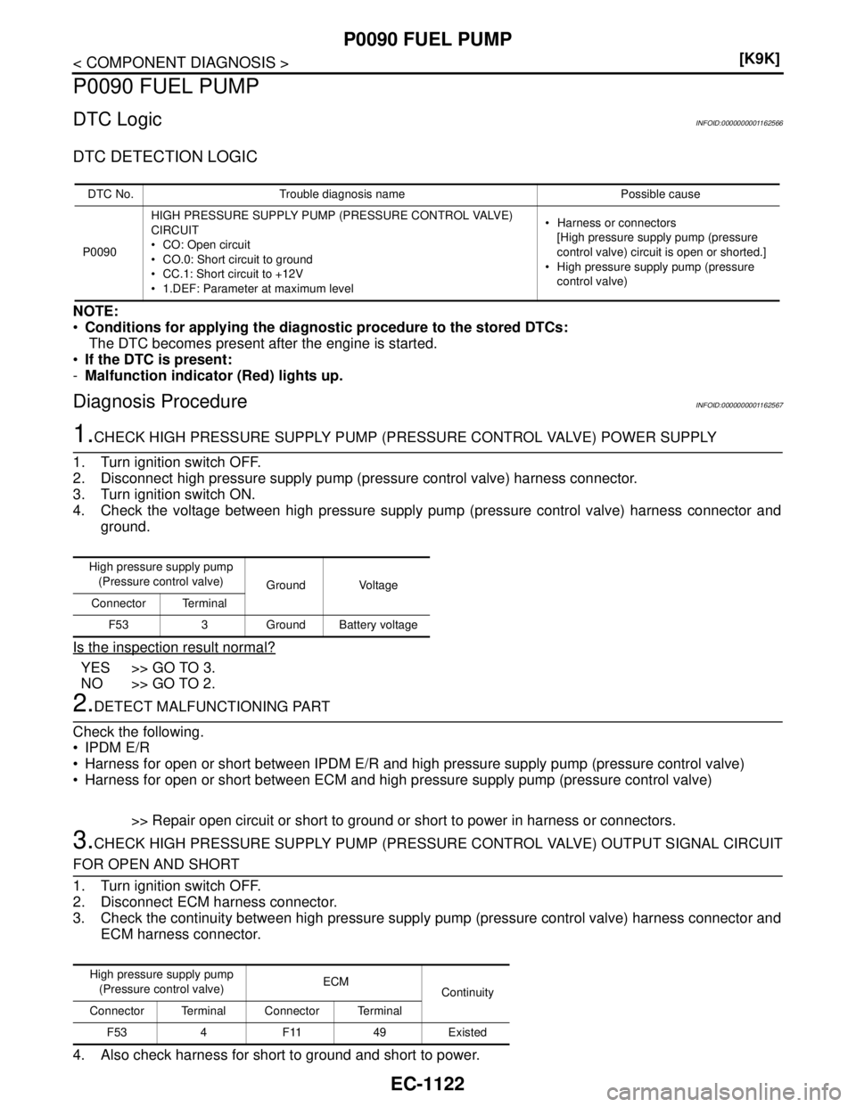
P0090 FUEL PUMP
P0090 FUEL PUMP
DTC LogicINFOID:0000000001162566
DTC DETECTION LOGIC
NOTE:
Conditions for applying the diagnostic procedure to the stored DTCs:
The DTC becomes present after the engine is started.
If the DTC is present:
-Malfunction indicator (Red) lights up.
Diagnosis ProcedureINFOID:0000000001162567
1.CHECK HIGH PRESSURE SUPPLY PUMP (PRESSURE CONTROL VALVE) POWER SUPPLY
1. Turn ignition switch OFF.
2. Disconnect high pressure supply pump (pressure control valve) harness connector.
3. Turn ignition switch ON.
4. Check the voltage between high pressure supply pump (pressure control valve) harness connector and
ground.
Is the inspection result normal?
YES >> GO TO 3.
NO >> GO TO 2.
2.DETECT MALFUNCTIONING PART
Check the following.
IPDM E/R
Harness for open or short between IPDM E/R and high pressure supply pump (pressure control valve)
Harness for open or short between ECM and high pressure supply pump (pressure control valve)
>> Repair open circuit or short to ground or short to power in harness or connectors.
3.CHECK HIGH PRESSURE SUPPLY PUMP (PRESSURE CONTROL VALVE) OUTPUT SIGNAL CIRCUIT
FOR OPEN AND SHORT
1. Turn ignition switch OFF.
2. Disconnect ECM harness connector.
3. Check the continuity between high pressure supply pump (pressure control valve) harness connector and
ECM harness connector.
4. Also check harness for short to ground and short to power.
DTC No. Trouble diagnosis name Possible cause
P0090HIGH PRESSURE SUPPLY PUMP (PRESSURE CONTROL VALVE)
CIRCUIT
CO: Open circuit
CO.0: Short circuit to ground
CC.1: Short circuit to +12V
1.DEF: Parameter at maximum level Harness or connectors
[High pressure supply pump (pressure
control valve) circuit is open or shorted.]
High pressure supply pump (pressure
control valve)
High pressure supply pump
(Pressure control valve)
Ground Voltage
Connector Terminal
F53 3 Ground Battery voltage
High pressure supply pump
(Pressure control valve)ECM
Continuity
Connector Terminal Connector Terminal
F53 4 F11 49 Existed
Page 2487 of 5883
EC-1138
< COMPONENT DIAGNOSIS >[K9K]
P0190 FRP SENSOR
P0190 FRP SENSOR
DescriptionINFOID:0000000001162592
The fuel rail pressure (FRP) sensor is placed to the fuel rail. It measures the fuel pressure in the fuel rail. The
sensor sends voltage signal to the ECM. As the pressure increases, the voltage rises.The ECM controls the
fuel pressure in the fuel rail. The ECM uses the signal from fuel rail pressure sensor as a feedback signal.
DTC LogicINFOID:0000000001162593
DTC DETECTION LOGIC
NOTE:
If DTC P0190 is displayed with DTC P0641, first perform trouble diagnosis for DTC P0641. Refer to
EC-1180, "
DTC Logic".
Conditions for applying the diagnostic procedure to the stored DTCs:
- The DTC is declared present after the ignition is switched on when the engine is running outside idle speed.
If the DTC is present:
-Malfunction indicator (Red) lights up.
Diagnosis ProcedureINFOID:0000000001162594
1.CHECK GROUND CONNECTIONS
1. Turn ignition switch OFF.
2. Check ground connection E15. Refer to Ground inspection in GI-58, "
Circuit Inspection".
Is the inspection result normal?
YES >> GO TO 2.
NO >> Repair or replace ground connection.
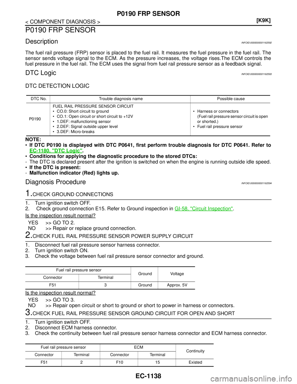
2.CHECK FUEL RAIL PRESSURE SENSOR POWER SUPPLY CIRCUIT
1. Disconnect fuel rail pressure sensor harness connector.
2. Turn ignition switch ON.
3. Check the voltage between fuel rail pressure sensor connector and ground.
Is the inspection result normal?
YES >> GO TO 3.
NO >> Repair open circuit or short to ground or short to power in harness or connectors.
3.CHECK FUEL RAIL PRESSURE SENSOR GROUND CIRCUIT FOR OPEN AND SHORT
1. Turn ignition switch OFF.
2. Disconnect ECM harness connector.
3. Check the continuity between fuel rail pressure sensor harness connector and ECM harness connector.
DTC No. Trouble diagnosis name Possible cause
P0190FUEL RAIL PRESSURE SENSOR CIRCUIT
CO.0: Short circuit to ground
CO.1: Open circuit or short circuit to +12V
1.DEF: malfunctioning sensor
2.DEF: Signal outside upper level
3.DEF: Micro-breaks Harness or connectors
(Fuel rail pressure sensor circuit is open
or shorted.)
Fuel rail pressure sensor
Fuel rail pressure sensor
Ground Voltage
Connector Terminal
F51 3 Ground Approx. 5V
Fuel rail pressure sensor ECM
Continuity
Connector Terminal Connector Terminal
F51 2 F10 15 Existed
Page 2489 of 5883
EC-1140
< COMPONENT DIAGNOSIS >[K9K]
P0200 FUEL INJECTOR
P0200 FUEL INJECTOR
DTC LogicINFOID:0000000001162596
DTC DETECTION LOGIC
NOTE:
Conditions for applying the diagnostic procedure to the stored DTCs:
The DTC is declared present after the engine has been started.
If the DTC is present:
-Malfunction indicator (Red) lights up.
Diagnosis ProcedureINFOID:0000000001162597
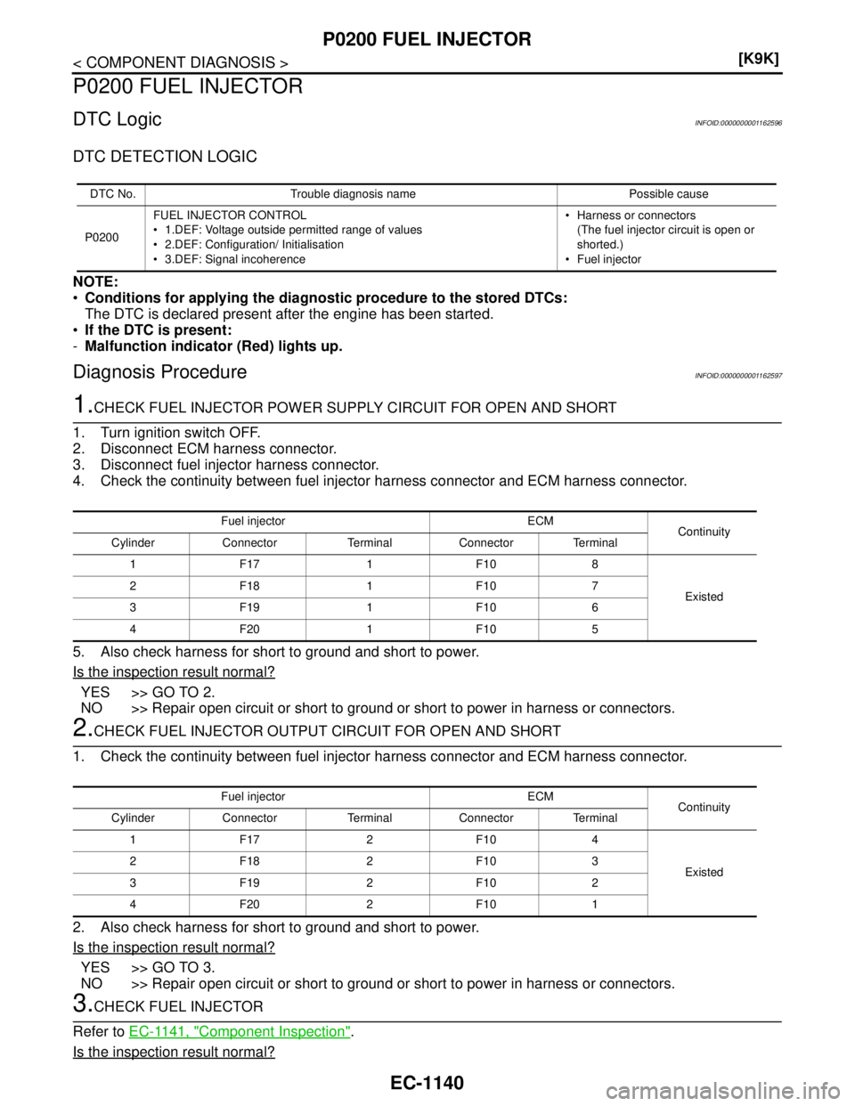
1.CHECK FUEL INJECTOR POWER SUPPLY CIRCUIT FOR OPEN AND SHORT
1. Turn ignition switch OFF.
2. Disconnect ECM harness connector.
3. Disconnect fuel injector harness connector.
4. Check the continuity between fuel injector harness connector and ECM harness connector.
5. Also check harness for short to ground and short to power.
Is the inspection result normal?
YES >> GO TO 2.
NO >> Repair open circuit or short to ground or short to power in harness or connectors.
2.CHECK FUEL INJECTOR OUTPUT CIRCUIT FOR OPEN AND SHORT
1. Check the continuity between fuel injector harness connector and ECM harness connector.
2. Also check harness for short to ground and short to power.
Is the inspection result normal?
YES >> GO TO 3.
NO >> Repair open circuit or short to ground or short to power in harness or connectors.
3.CHECK FUEL INJECTOR
Refer to EC-1141, "
Component Inspection".
Is the inspection result normal?
DTC No. Trouble diagnosis name Possible cause
P0200FUEL INJECTOR CONTROL
1.DEF: Voltage outside permitted range of values
2.DEF: Configuration/ Initialisation
3.DEF: Signal incoherence Harness or connectors
(The fuel injector circuit is open or
shorted.)
Fuel injector
Fuel injector ECM
Continuity
Cylinder Connector Terminal Connector Terminal
1F17 1F108
Existed 2F18 1F107
3F19 1F106
4F20 1F105
Fuel injector ECM
Continuity
Cylinder Connector Terminal Connector Terminal
1F17 2F104
Existed 2F18 2F103
3F19 2F102
4F20 2F101
Page 2491 of 5883
EC-1142
< COMPONENT DIAGNOSIS >[K9K]
P0201, P0202, P0203, P0204 FUEL INJECTOR
P0201, P0202, P0203, P0204 FUEL INJECTOR
DTC LogicINFOID:0000000001162599
DTC DETECTION LOGIC
NOTE:
Conditions for applying the diagnostic procedure to the stored DTCs:
The DTC is declared present after the engine has been started.
If the DTC is present:
-Malfunction indicator (Red) lights up.
-Malfunction indicator (Yellow) lights up.
Diagnosis ProcedureINFOID:0000000001162600
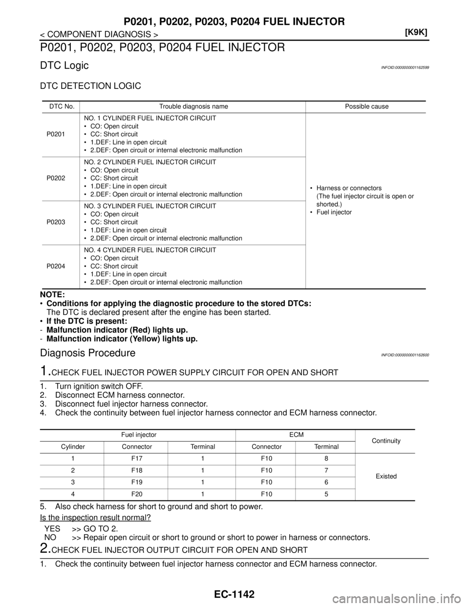
1.CHECK FUEL INJECTOR POWER SUPPLY CIRCUIT FOR OPEN AND SHORT
1. Turn ignition switch OFF.
2. Disconnect ECM harness connector.
3. Disconnect fuel injector harness connector.
4. Check the continuity between fuel injector harness connector and ECM harness connector.
5. Also check harness for short to ground and short to power.
Is the inspection result normal?
YES >> GO TO 2.
NO >> Repair open circuit or short to ground or short to power in harness or connectors.
2.CHECK FUEL INJECTOR OUTPUT CIRCUIT FOR OPEN AND SHORT
1. Check the continuity between fuel injector harness connector and ECM harness connector.
DTC No. Trouble diagnosis name Possible cause
P0201NO. 1 CYLINDER FUEL INJECTOR CIRCUIT
CO: Open circuit
CC: Short circuit
1.DEF: Line in open circuit
2.DEF: Open circuit or internal electronic malfunction
Harness or connectors
(The fuel injector circuit is open or
shorted.)
Fuel injector P0202NO. 2 CYLINDER FUEL INJECTOR CIRCUIT
CO: Open circuit
CC: Short circuit
1.DEF: Line in open circuit
2.DEF: Open circuit or internal electronic malfunction
P0203NO. 3 CYLINDER FUEL INJECTOR CIRCUIT
CO: Open circuit
CC: Short circuit
1.DEF: Line in open circuit
2.DEF: Open circuit or internal electronic malfunction
P0204NO. 4 CYLINDER FUEL INJECTOR CIRCUIT
CO: Open circuit
CC: Short circuit
1.DEF: Line in open circuit
2.DEF: Open circuit or internal electronic malfunction
Fuel injector ECM
Continuity
Cylinder Connector Terminal Connector Terminal
1F17 1F108
Existed 2F18 1F107
3F19 1F106
4F20 1F105
Page 2496 of 5883
P0235 TC BOOST SENSOR
EC-1147
< COMPONENT DIAGNOSIS >[K9K]
C
D
E
F
G
H
I
J
K
L
MA
EC
N
P O
P0235 TC BOOST SENSOR
DescriptionINFOID:0000000001162608
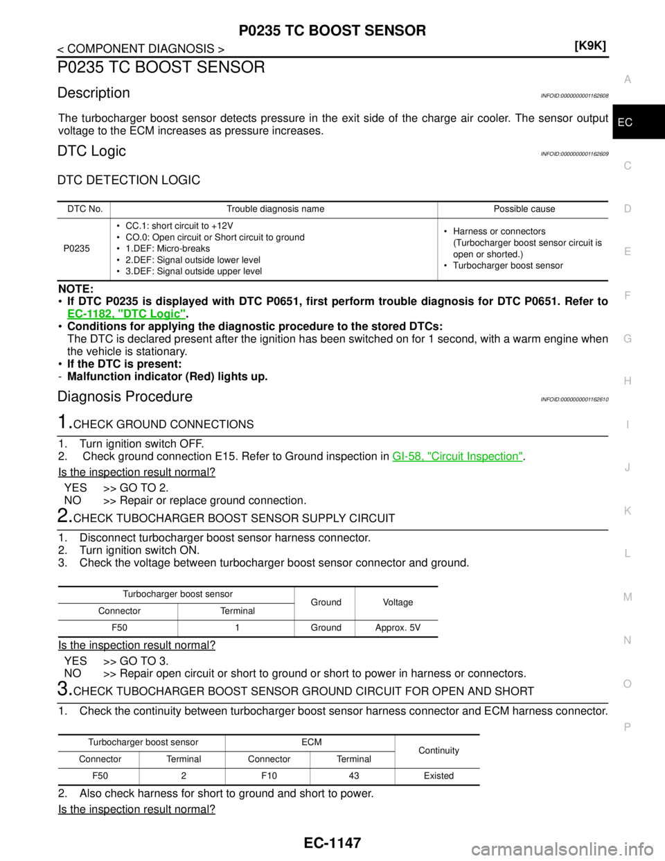
The turbocharger boost sensor detects pressure in the exit side of the charge air cooler. The sensor output
voltage to the ECM increases as pressure increases.
DTC LogicINFOID:0000000001162609
DTC DETECTION LOGIC
NOTE:
If DTC P0235 is displayed with DTC P0651, first perform trouble diagnosis for DTC P0651. Refer to
EC-1182, "
DTC Logic".
Conditions for applying the diagnostic procedure to the stored DTCs:
The DTC is declared present after the ignition has been switched on for 1 second, with a warm engine when
the vehicle is stationary.
If the DTC is present:
-Malfunction indicator (Red) lights up.
Diagnosis ProcedureINFOID:0000000001162610
1.CHECK GROUND CONNECTIONS
1. Turn ignition switch OFF.
2. Check ground connection E15. Refer to Ground inspection in GI-58, "
Circuit Inspection".
Is the inspection result normal?
YES >> GO TO 2.
NO >> Repair or replace ground connection.
2.CHECK TUBOCHARGER BOOST SENSOR SUPPLY CIRCUIT
1. Disconnect turbocharger boost sensor harness connector.
2. Turn ignition switch ON.
3. Check the voltage between turbocharger boost sensor connector and ground.
Is the inspection result normal?
YES >> GO TO 3.
NO >> Repair open circuit or short to ground or short to power in harness or connectors.
3.CHECK TUBOCHARGER BOOST SENSOR GROUND CIRCUIT FOR OPEN AND SHORT
1. Check the continuity between turbocharger boost sensor harness connector and ECM harness connector.
2. Also check harness for short to ground and short to power.
Is the inspection result normal?
DTC No. Trouble diagnosis name Possible cause
P0235 CC.1: short circuit to +12V
CO.0: Open circuit or Short circuit to ground
1.DEF: Micro-breaks
2.DEF: Signal outside lower level
3.DEF: Signal outside upper level Harness or connectors
(Turbocharger boost sensor circuit is
open or shorted.)
Turbocharger boost sensor
Turbocharger boost sensor
Ground Voltage
Connector Terminal
F50 1 Ground Approx. 5V
Turbocharger boost sensor ECM
Continuity
Connector Terminal Connector Terminal
F50 2 F10 43 Existed
Page 2498 of 5883
P0335 CKP SENSOR
EC-1149
< COMPONENT DIAGNOSIS >[K9K]
C
D
E
F
G
H
I
J
K
L
MA
EC
N
P O
P0335 CKP SENSOR
DTC LogicINFOID:0000000001162612
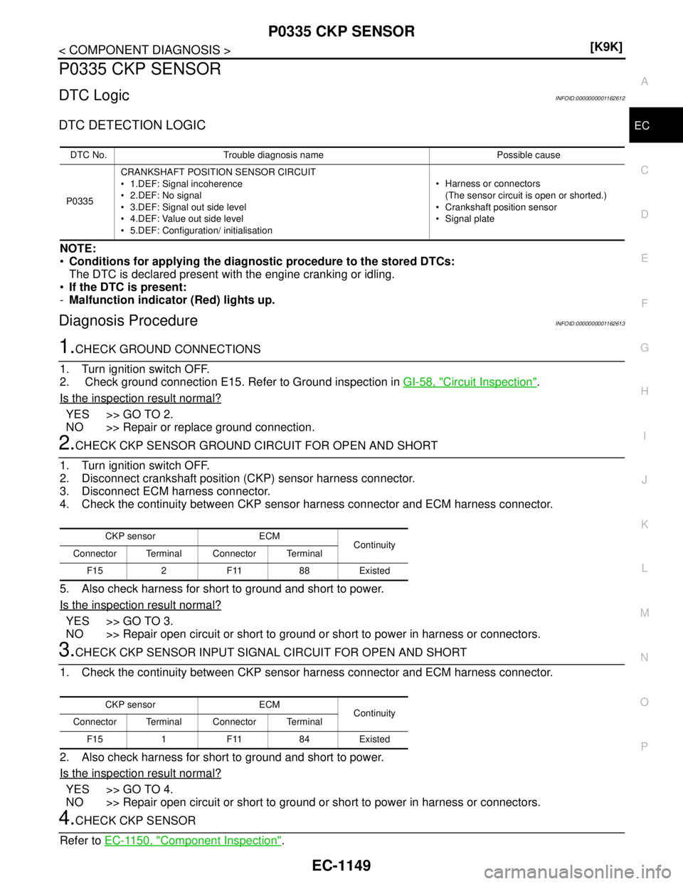
DTC DETECTION LOGIC
NOTE:
Conditions for applying the diagnostic procedure to the stored DTCs:
The DTC is declared present with the engine cranking or idling.
If the DTC is present:
-Malfunction indicator (Red) lights up.
Diagnosis ProcedureINFOID:0000000001162613
1.CHECK GROUND CONNECTIONS
1. Turn ignition switch OFF.
2. Check ground connection E15. Refer to Ground inspection in GI-58, "
Circuit Inspection".
Is the inspection result normal?
YES >> GO TO 2.
NO >> Repair or replace ground connection.
2.CHECK CKP SENSOR GROUND CIRCUIT FOR OPEN AND SHORT
1. Turn ignition switch OFF.
2. Disconnect crankshaft position (CKP) sensor harness connector.
3. Disconnect ECM harness connector.
4. Check the continuity between CKP sensor harness connector and ECM harness connector.
5. Also check harness for short to ground and short to power.
Is the inspection result normal?
YES >> GO TO 3.
NO >> Repair open circuit or short to ground or short to power in harness or connectors.
3.CHECK CKP SENSOR INPUT SIGNAL CIRCUIT FOR OPEN AND SHORT
1. Check the continuity between CKP sensor harness connector and ECM harness connector.
2. Also check harness for short to ground and short to power.
Is the inspection result normal?
YES >> GO TO 4.
NO >> Repair open circuit or short to ground or short to power in harness or connectors.
4.CHECK CKP SENSOR
Refer to EC-1150, "
Component Inspection".
DTC No. Trouble diagnosis name Possible cause
P0335CRANKSHAFT POSITION SENSOR CIRCUIT
1.DEF: Signal incoherence
2.DEF: No signal
3.DEF: Signal out side level
4.DEF: Value out side level
5.DEF: Configuration/ initialisation Harness or connectors
(The sensor circuit is open or shorted.)
Crankshaft position sensor
Signal plate
CKP sensor ECM
Continuity
Connector Terminal Connector Terminal
F15 2 F11 88 Existed
CKP sensor ECM
Continuity
Connector Terminal Connector Terminal
F15 1 F11 84 Existed