steering system NISSAN TIIDA 2007 Service Manual PDF
[x] Cancel search | Manufacturer: NISSAN, Model Year: 2007, Model line: TIIDA, Model: NISSAN TIIDA 2007Pages: 5883, PDF Size: 78.95 MB
Page 1395 of 5883
EC-46
< FUNCTION DIAGNOSIS >[HR16DE (WITH EURO-OBD)]
MULTIPORT FUEL INJECTION SYSTEM
Component Description
INFOID:0000000001161145
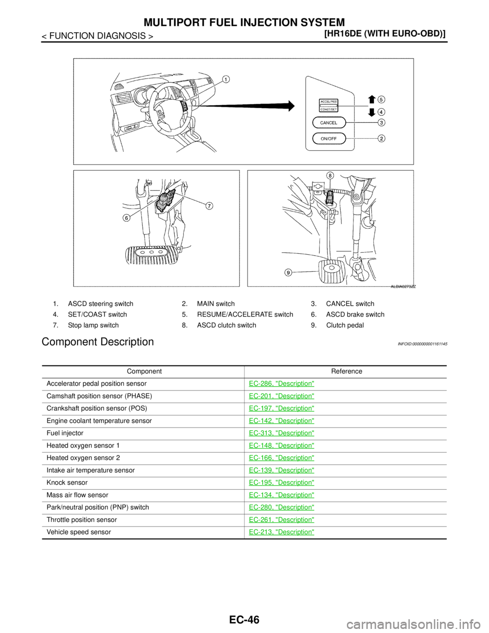
1. ASCD steering switch 2. MAIN switch 3. CANCEL switch
4. SET/COAST switch 5. RESUME/ACCELERATE switch 6. ASCD brake switch
7. Stop lamp switch 8. ASCD clutch switch 9. Clutch pedal
ALBIA0273ZZ
Component Reference
Accelerator pedal position sensorEC-286, "
Description"
Camshaft position sensor (PHASE)EC-201, "Description"
Crankshaft position sensor (POS)EC-197, "Description"
Engine coolant temperature sensorEC-142, "Description"
Fuel injectorEC-313, "Description"
Heated oxygen sensor 1EC-148, "Description"
Heated oxygen sensor 2EC-166, "Description"
Intake air temperature sensorEC-139, "Description"
Knock sensorEC-195, "Description"
Mass air flow sensorEC-134, "Description"
Park/neutral position (PNP) switchEC-280, "Description"
Throttle position sensorEC-261, "Description"
Vehicle speed sensorEC-213, "Description"
Page 1402 of 5883
ELECTRIC IGNITION SYSTEM
EC-53
< FUNCTION DIAGNOSIS >[HR16DE (WITH EURO-OBD)]
C
D
E
F
G
H
I
J
K
L
MA
EC
N
P O
Component DescriptionINFOID:0000000001161149
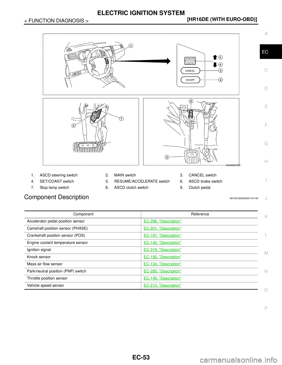
1. ASCD steering switch 2. MAIN switch 3. CANCEL switch
4. SET/COAST switch 5. RESUME/ACCELERATE switch 6. ASCD brake switch
7. Stop lamp switch 8. ASCD clutch switch 9. Clutch pedal
ALBIA0273ZZ
Component Reference
Accelerator pedal position sensorEC-286, "
Description"
Camshaft position sensor (PHASE)EC-201, "Description"
Crankshaft position sensor (POS)EC-197, "Description"
Engine coolant temperature sensorEC-142, "Description"
Ignition signalEC-319, "Description"
Knock sensorEC-195, "Description"
Mass air flow sensorEC-134, "Description"
Park/neutral position (PNP) switchEC-280, "Description"
Throttle position sensorEC-145, "Description"
Vehicle speed sensorEC-213, "Description"
Page 1403 of 5883
EC-54
< FUNCTION DIAGNOSIS >[HR16DE (WITH EURO-OBD)]
AIR CONDITIONING CUT CONTROL
AIR CONDITIONING CUT CONTROL
System DiagramINFOID:0000000001161150
System DescriptionINFOID:0000000001161151
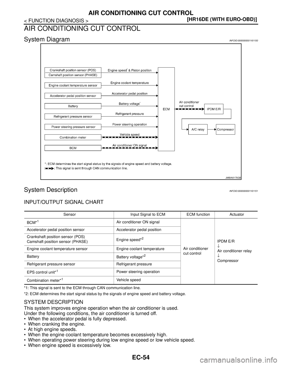
INPUT/OUTPUT SIGNAL CHART
*1: This signal is sent to the ECM through CAN communication line.
*2: ECM determines the start signal status by the signals of engine speed and battery voltage.
SYSTEM DESCRIPTION
This system improves engine operation when the air conditioner is used.
Under the following conditions, the air conditioner is turned off.
When the accelerator pedal is fully depressed.
When cranking the engine.
At high engine speeds.
When the engine coolant temperature becomes excessively high.
When operating power steering during low engine speed or low vehicle speed.
When engine speed is excessively low.
JMBIA0175GB
Sensor Input Signal to ECM ECM function Actuator
BCM*
1Air conditioner ON signal
Air conditioner
cut controlIPDM E/R
↓
Air conditioner relay
↓
Compressor Accelerator pedal position sensor Accelerator pedal position
Crankshaft position sensor (POS)
Camshaft position sensor (PHASE)Engine speed*
2
Engine coolant temperature sensor Engine coolant temperature
Battery
Battery voltage*
2
Refrigerant pressure sensor Refrigerant pressure
EPS control unit*
1Power steering operation
Combination meter*
1Vehicle speed
Page 1410 of 5883
AUTOMATIC SPEED CONTROL DEVICE (ASCD)
EC-61
< FUNCTION DIAGNOSIS >[HR16DE (WITH EURO-OBD)]
C
D
E
F
G
H
I
J
K
L
MA
EC
N
P O
AUTOMATIC SPEED CONTROL DEVICE (ASCD)
System DiagramINFOID:0000000001161154
System DescriptionINFOID:0000000001161155
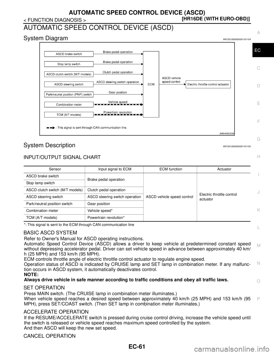
INPUT/OUTPUT SIGNAL CHART
*: This signal is sent to the ECM through CAN communication line
BASIC ASCD SYSTEM
Refer to Owner's Manual for ASCD operating instructions.
Automatic Speed Control Device (ASCD) allows a driver to keep vehicle at predetermined constant speed
without depressing accelerator pedal. Driver can set vehicle speed in advance between approximately 40 km/
h (25 MPH) and 153 km/h (95 MPH).
ECM controls throttle angle of electric throttle control actuator to regulate engine speed.
Operation status of ASCD is indicated by CRUISE lamp and SET lamp in combination meter. If any malfunc-
tion occurs in ASCD system, it automatically deactivates control.
NOTE:
Always drive vehicle in safe manner according to traffic conditions and obey all traffic laws.
SET OPERATION
Press MAIN switch. (The CRUISE lamp in combination meter illuminates.)
When vehicle speed reaches a desired speed between approximately 40 km/h (25 MPH) and 153 km/h (95
MPH), press SET/COAST switch. (Then SET lamp in combination meter illuminates.)
ACCELERATE OPERATION
If the RESUME/ACCELERATE switch is pressed during cruise control driving, increase the vehicle speed until
the switch is released or vehicle speed reaches maximum speed controlled by the system.
And then ASCD will keep the new set speed.
CANCEL OPERATION
JMBIA0823GB
Sensor Input signal to ECM ECM function Actuator
ASCD brake switch
Brake pedal operation
ASCD vehicle speed controlElectric throttle control
actuator Stop lamp switch
ASCD clutch switch (M/T models) Clutch pedal operation
ASCD steering switch ASCD steering switch operation
Park/neutral position switch Gear position
Combination meter Vehicle speed*
TCM (A/T models) Powertrain revolution*
Page 1411 of 5883
EC-62
< FUNCTION DIAGNOSIS >[HR16DE (WITH EURO-OBD)]
AUTOMATIC SPEED CONTROL DEVICE (ASCD)
When any of following conditions exist, cruise operation will be canceled.
CANCEL switch is pressed
More than 2 switches at ASCD steering switch are pressed at the same time (Set speed will be cleared)
Brake pedal is depressed
Clutch pedal is depressed or gear position is changed to neutral position (M/T models).
Selector lever is changed to N, P, R position (A/T models).
Vehicle speed decreased to 13 km/h (8 MPH) lower than the set speed
TCS system is operated
When the ECM detects any of the following conditions, the ECM will cancel the cruise operation and inform
the driver by blinking indicator lamp.
Engine coolant temperature is slightly higher than the normal operating temperature, CRUISE lamp may
blink slowly.
When the engine coolant temperature decreases to the normal operating temperature, CRUISE lamp will
stop blinking and the cruise operation will be able to work by pressing SET/COAST switch or RESUME/
ACCELERATE switch.
Malfunction for some self-diagnoses regarding ASCD control: SET lamp will blink quickly.
If MAIN switch is turned to OFF during ASCD is activated, all of ASCD operations will be canceled and vehicle
speed memory will be erased.
COAST OPERATION
When the SET/COAST switch is pressed during cruise control driving, decrease vehicle set speed until the
switch is released. And then ASCD will keep the new set speed.
RESUME OPERATION
When the RESUME/ACCELERATE switch is pressed after cancel operation other than pressing MAIN switch
is performed, vehicle speed will return to last set speed. To resume vehicle set speed, vehicle condition must
meet following conditions.
Brake pedal is released
Clutch pedal is released (M/T models)
Selector lever is in other than P and N positions (A/T models)
Vehicle speed is greater than 40 km/h (25 MPH) and less than 153km/h (95 MPH)
Page 1435 of 5883
EC-86
< FUNCTION DIAGNOSIS >[HR16DE (WITH EURO-OBD)]
EVAPORATIVE EMISSION SYSTEM
Component Description
INFOID:0000000001161166
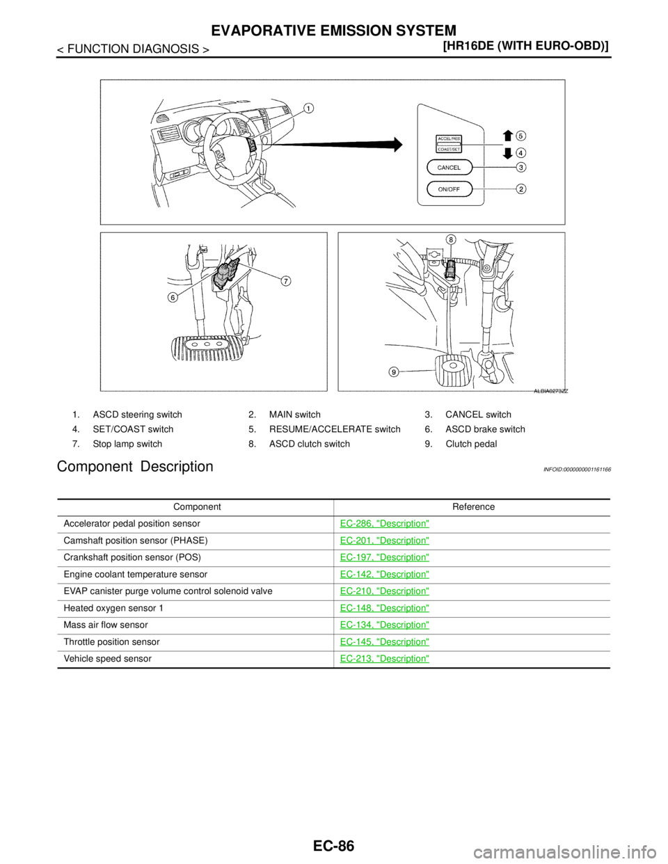
1. ASCD steering switch 2. MAIN switch 3. CANCEL switch
4. SET/COAST switch 5. RESUME/ACCELERATE switch 6. ASCD brake switch
7. Stop lamp switch 8. ASCD clutch switch 9. Clutch pedal
ALBIA0273ZZ
Component Reference
Accelerator pedal position sensorEC-286, "
Description"
Camshaft position sensor (PHASE)EC-201, "Description"
Crankshaft position sensor (POS)EC-197, "Description"
Engine coolant temperature sensorEC-142, "Description"
EVAP canister purge volume control solenoid valveEC-210, "Description"
Heated oxygen sensor 1EC-148, "Description"
Mass air flow sensorEC-134, "Description"
Throttle position sensorEC-145, "Description"
Vehicle speed sensorEC-213, "Description"
Page 1457 of 5883
EC-108
< FUNCTION DIAGNOSIS >[HR16DE (WITH EURO-OBD)]
ON BOARD DIAGNOSTIC (OBD) SYSTEM
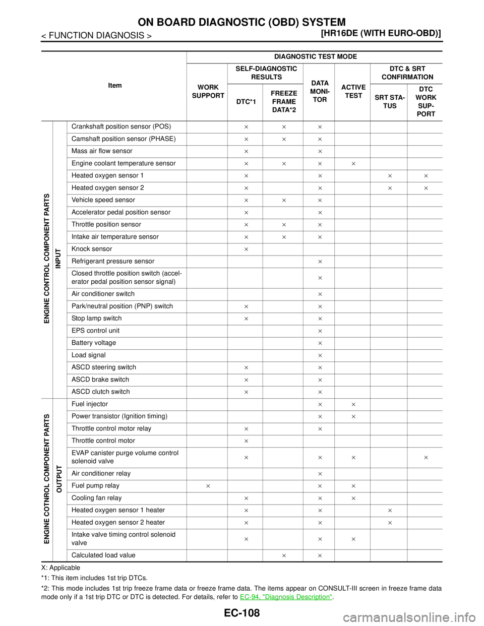
X: Applicable
*1: This item includes 1st trip DTCs.
*2: This mode includes 1st trip freeze frame data or freeze frame data. The items appear on CONSULT-III screen in freeze frame data
mode only if a 1st trip DTC or DTC is detected. For details, refer to EC-94, "
Diagnosis Description". ItemDIAGNOSTIC TEST MODE
WORK
SUPPORTSELF-DIAGNOSTIC
RESULTS
DATA
MONI-
TORACTIVE
TESTDTC & SRT
CONFIRMATION
DTC*1FREEZE
FRAME
DATA*2SRT STA-
TUSDTC
WORK
SUP-
PORT
ENGINE CONTROL COMPONENT PARTS
INPUT
Crankshaft position sensor (POS)×××
Camshaft position sensor (PHASE)×××
Mass air flow sensor××
Engine coolant temperature sensor××××
Heated oxygen sensor 1××××
Heated oxygen sensor 2××××
Vehicle speed sensor×××
Accelerator pedal position sensor××
Throttle position sensor×××
Intake air temperature sensor×××
Knock sensor×
Refrigerant pressure sensor×
Closed throttle position switch (accel-
erator pedal position sensor signal)×
Air conditioner switch×
Park/neutral position (PNP) switch××
Stop lamp switch××
EPS control unit×
Battery voltage×
Load signal×
ASCD steering switch××
ASCD brake switch××
ASCD clutch switch××
ENGINE COTNROL COMPONENT PARTS
OUTPUT
Fuel injector××
Power transistor (Ignition timing)××
Throttle control motor relay××
Throttle control motor×
EVAP canister purge volume control
solenoid valve××××
Air conditioner relay×
Fuel pump relay×××
Cooling fan relay×××
Heated oxygen sensor 1 heater×××
Heated oxygen sensor 2 heater×××
Intake valve timing control solenoid
valve×××
Calculated load value××
Page 1460 of 5883
ON BOARD DIAGNOSTIC (OBD) SYSTEM
EC-111
< FUNCTION DIAGNOSIS >[HR16DE (WITH EURO-OBD)]
C
D
E
F
G
H
I
J
K
L
MA
EC
N
P O
CLSD THL POS ON/OFF Indicates idle position [ON/OFF] computed by
ECM according to the accelerator pedal position
sensor signal.
AIR COND SIG ON/OFF Indicates [ON/OFF] condition of the air condition-
er switch as determined by the air conditioner sig-
nal.
P/N POSI SW ON/OFF Indicates [ON/OFF] condition from the park/neu-
tral position (PNP) switch signal.
PW/ST SIGNAL ON/OFF [ON/OFF] condition of the power steering system
(determined by the signal sent from EPS control
unit) is indicated.
LOAD SIGNAL ON/OFF Indicates [ON/OFF] condition from the electrical
load signal.
ON: Rear window defogger switch is ON and/or
lighting switch is in 2nd position.
OFF: Both rear window defogger switch and light-
ing switch are OFF.
IGNITION SW ON/OFF Indicates [ON/OFF] condition from ignition switch
signal.
CLUTCH P/P SW ON/OFF Indicates [ON/OFF] condition from the clutch
switch signal.
HEATER FAN SW ON/OFF Indicates [ON/OFF] condition from the heater fan
switch signal.
BRAKE SW ON/OFF Indicates [ON/OFF] condition from the stop lamp
switch signal.
INJ PULSE-B1 msec Indicates the actual fuel injection pulse width
compensated by ECM according to the input sig-
nals. When the engine is stopped, a certain
computed value is indicated.
IGN TIMING BTDC Indicates the ignition timing computed by ECM
according to the input signals. When the engine is stopped, a certain
value is indicated.
CAL/LD VALUE % “Calculated load value” indicates the value of the
current air flow divided by peak air flow.
MASS AIRFLOW g·m/s Indicates the mass air flow computed by ECM ac-
cording to the signal voltage of the mass air flow
sensor.
PURG VOL C/V % Indicates the EVAP canister purge volume con-
trol solenoid valve control value computed by the
ECM according to the input signals.
The opening becomes larger as the value in-
creases.
INT/V TIM (B1)°CA Indicates [°CA] of intake camshaft advance an-
gle.
INT/V SOL-B1
% The control value of the intake valve timing con-
trol solenoid valve (determined by ECM accord-
ing to the input signals) is indicated.
The advance angle becomes larger as the value
increases.
AIR COND RLY ON/OFF The air conditioner relay control condition (deter-
mined by ECM according to the input signals) is
indicated.
FUEL PUMP RLY ON/OFF Indicates the fuel pump relay control condition
determined by ECM according to the input sig-
nals.
THRTL RELAY ON/OFF Indicates the throttle control motor relay control
condition determined by the ECM according to
the input signals. Monitored item Unit Description Remarks
Page 1465 of 5883
EC-116
< COMPONENT DIAGNOSIS >[HR16DE (WITH EURO-OBD)]
TROUBLE DIAGNOSIS - SPECIFICATION VALUE
COMPONENT DIAGNOSIS
TROUBLE DIAGNOSIS - SPECIFICATION VALUE
DescriptionINFOID:0000000001670886
The specification (SP) value indicates the tolerance of the value that is displayed in “SPEC” of “DATA MONI-
TOR” mode of CONSULT-III during normal operation of the Engine Control System. When the value in “SPEC”
of “DATA MONITOR” mode is within the SP value, the Engine Control System is confirmed OK. When the
value in “SPEC” of “DATA MONITOR” mode is NOT within the SP value, the Engine Control System may have
one or more malfunctions.
The SP value is used to detect malfunctions that may affect the Engine Control System, but will not light the
MI.
The SP value will be displayed for the following three items:
B/FUEL SCHDL (The fuel injection pulse width programmed into ECM prior to any learned on board correc-
tion)
A/F ALPHA-B1 (The mean value of air-fuel ratio feedback correction factor per cycle)
MAS A/F SE-B1 (The signal voltage of the mass air flow sensor)
Component Function CheckINFOID:0000000001670887
1.START
Make sure that all of the following conditions are satisfied.
Vehicle driven distance: More than 5,000 km (3,107 miles)
Barometric pressure: 98.3 - 104.3 kPa (0.983 - 1.043 bar, 1.003 - 1.064 kg/cm
2, 14.25 - 15.12 psi)
Atmospheric temperature: 20 - 30°C (68 - 86°F)
Engine coolant temperature: 75 - 95°C (167 - 203°F)
Transmission: Warmed-up
- After the engine is warmed up to normal operating temperature, drive vehicle for 5 minutes.
Electrical load: Not applied*
Engine speed: Idle
*: Rear window defogger switch, air conditioner switch, lighting switch are OFF. Steering wheel is straight
ahead.
>> GO TO 2.
2.PERFORM “SPEC” OF “DATA MONITOR” MODE
With CONSULT-III
NOTE:
Perform “SPEC” in “DATA MONITOR” mode in maximum scale display.
1. Perform EC-22, "
BASIC INSPECTION : Special Repair Requirement".
2. Select “B/FUEL SCHDL”, “A/F ALPHA-B1” and “MAS A/F SE-B1” in “SPEC” of “DATA MONITOR” mode
with CONSULT-III.
3. Make sure that monitor items are within the SP value.
Is the inspection result normal?
YES >> END
NO >> Go to EC-117, "
Diagnosis Procedure".
Page 1616 of 5883
P1564 ASCD STEERING SWITCH
EC-267
< COMPONENT DIAGNOSIS >[HR16DE (WITH EURO-OBD)]
C
D
E
F
G
H
I
J
K
L
MA
EC
N
P O
P1564 ASCD STEERING SWITCH
DescriptionINFOID:0000000001671042
ASCD steering switch has variant values of electrical resistance for each button. ECM reads voltage variation
of switch, and determines which button is operated.
Refer to EC-61, "
System Diagram" for the ASCD function.
DTC LogicINFOID:0000000001671043
DTC DETECTION LOGIC
NOTE:
If DTC P1564 is displayed with DTC P0605, first perform the trouble diagnosis for DTC P0605. Refer to
EC-215, "
DTC Logic".
DTC CONFIRMATION PROCEDURE
1.PRECONDITIONING
If DTC Confirmation Procedure has been previously conducted, always turn ignition switch OFF and wait at
least 10 seconds before conducting the next test.
>> GO TO 2.
2.PERFORM DTC CONFIRMATION PROCEDURE
1. Turn ignition switch ON.
2. Wait at least 10 seconds.
3. Press MAIN switch for at least 10 seconds, then release it and wait at least 10 seconds.
4. Press CANCEL switch for at least 10 seconds, then release it and wait at least 10 seconds.
5. Press RESUME/ACCELERATE switch for at least 10 seconds, then release it and wait at least 10 sec-
onds.
6. Press SET/COAST switch for at least 10 seconds, then release it and wait at least 10 seconds.
7. Check DTC.
Is DTC detected?
YES >> Go to EC-267, "Diagnosis Procedure".
NO >> INSPECTION END
Diagnosis ProcedureINFOID:0000000001671044
1.CHECK GROUND CONNECTION
1. Turn ignition switch OFF.
2. Check ground connection E15. Refer to Ground Inspection in GI-58, "
Circuit Inspection".
Is the inspection result normal?
YS >> GO TO 2.
NO >> Repair or replace ground connection.
2.CHECK ASCD STEERING SWITCH CIRCUIT
With CONSULT-III
1. Turn ignition switch ON.
DTC No.Trouble diagnosis
nameDTC detecting condition Possible cause
P1564 ASCD steering switch An excessively high voltage signal from the
ASCD steering switch is sent to ECM.
ECM detects that input signal from the
ASCD steering switch is out of the specified
range.
ECM detects that the ASCD steering switch
is stuck ON. Harness or connectors
(The switch circuit is open or shorted.)
ASCD steering switch
ECM