steering system NISSAN TIIDA 2007 Service Owner's Manual
[x] Cancel search | Manufacturer: NISSAN, Model Year: 2007, Model line: TIIDA, Model: NISSAN TIIDA 2007Pages: 5883, PDF Size: 78.95 MB
Page 234 of 5883
BRC-1
BRAKES
C
D
E
G
H
I
J
K
L
M
SECTION BRC
A
B
BRC
N
O
P
CONTENTS
BRAKE CONTROL SYSTEM
ABS
BASIC INSPECTION ....................................
6
DIAGNOSIS AND REPAIR WORKFLOW ..........6
Work Flow .................................................................6
Diagnostic Work Sheet ..............................................9
INSPECTION AND ADJUSTMENT ....................10
ADDITIONAL SERVICE WHEN REPLACING
CONTROL UNIT ........................................................
10
ADDITIONAL SERVICE WHEN REPLACING
CONTROL UNIT : Description ................................
10
ADDITIONAL SERVICE WHEN REPLACING
CONTROL UNIT : Special Repair Requirement .....
10
ADJUSTMENT OF STEERING ANGLE SENSOR
NEUTRAL POSITION ................................................
10
ADJUSTMENT OF STEERING ANGLE SENSOR
NEUTRAL POSITION : Description ........................
10
ADJUSTMENT OF STEERING ANGLE SENSOR
NEUTRAL POSITION : Special Repair Require-
ment ........................................................................
10
CALIBRATION OF DECEL G SENSOR ...................11
CALIBRATION OF DECEL G SENSOR : Descrip-
tion ..........................................................................
11
CALIBRATION OF DECEL G SENSOR : Special
Repair Requirement ................................................
12
FUNCTION DIAGNOSIS ..............................13
VDC ....................................................................13
System Diagram ......................................................13
System Description .................................................13
Component Parts Location ......................................14
Component Description ...........................................15
TCS .....................................................................16
System Diagram ......................................................16
System Description .................................................16
Component Parts Location ......................................17
Component Description ...........................................18
ABS ...................................................................19
System Diagram ......................................................19
System Description ..................................................19
Component Parts Location ......................................20
Component Description ...........................................21
EBD ...................................................................22
System Diagram ......................................................22
System Description ..................................................22
Component Parts Location ......................................23
Component Description ...........................................24
DIAGNOSIS SYSTEM [ABS ACTUATOR
AND ELECTRIC UNIT (CONTROL UNIT)] .......
25
CONSULT-III Function (ABS) ..................................25
COMPONENT DIAGNOSIS .........................30
C1101, C1102, C1103, C1104 WHEEL SEN-
SOR-1 ................................................................
30
Description ...............................................................30
DTC Logic ................................................................30
Diagnosis Procedure ...............................................30
Component Inspection .............................................32
Special Repair Requirement ....................................32
C1105, C1106, C1107, C1108 WHEEL SEN-
SOR-2 ................................................................
33
Description ...............................................................33
DTC Logic ................................................................33
Diagnosis Procedure ...............................................33
Component Inspection .............................................35
Special Repair Requirement ....................................35
C1109 POWER AND GROUND SYSTEM ........36
Description ...............................................................36
DTC Logic ................................................................36
Diagnosis Procedure ...............................................36
Special Repair Requirement ....................................37
Page 236 of 5883
BRC-3
C
D
E
G
H
I
J
K
L
MA
B
BRC
N
O
P
PREPARATION ...........................................82
PREPARATION ..................................................82
Special Service Tool ...............................................82
REMOVAL AND INSTALLATION ...............83
WHEEL SENSORS ............................................83
Removal and Installation .........................................83
SENSOR ROTOR ...............................................84
Removal and Installation .........................................84
ACTUATOR AND ELECTRIC UNIT (ASSEM-
BLY) ....................................................................
85
Removal and Installation .........................................85
ESP/TCS/ABS
BASIC INSPECTION ...................................
86
DIAGNOSIS AND REPAIR WORKFLOW .........86
Work Flow ...............................................................86
Diagnostic Work Sheet ............................................89
INSPECTION AND ADJUSTMENT ....................90
ADDITIONAL SERVICE WHEN REPLACING
CONTROL UNIT ........................................................
90
ADDITIONAL SERVICE WHEN REPLACING
CONTROL UNIT : Description ................................
90
ADDITIONAL SERVICE WHEN REPLACING
CONTROL UNIT : Special Repair Requirement .....
90
ADJUSTMENT OF STEERING ANGLE SENSOR
NEUTRAL POSITION ................................................
90
ADJUSTMENT OF STEERING ANGLE SENSOR
NEUTRAL POSITION : Description ........................
90
ADJUSTMENT OF STEERING ANGLE SENSOR
NEUTRAL POSITION : Special Repair Require-
ment ........................................................................
90
CALIBRATION OF DECEL G SENSOR ...................91
CALIBRATION OF DECEL G SENSOR : Descrip-
tion ..........................................................................
91
CALIBRATION OF DECEL G SENSOR : Special
Repair Requirement ................................................
92
FUNCTION DIAGNOSIS ..............................93
VDC ....................................................................93
System Diagram ......................................................93
System Description .................................................93
Component Parts Location ......................................94
Component Description ...........................................95
TCS .....................................................................96
System Diagram ......................................................96
System Description .................................................96
Component Parts Location ......................................97
Component Description ...........................................98
ABS ....................................................................99
System Diagram ......................................................99
System Description ..................................................99
Component Parts Location ....................................100
Component Description .........................................101
EBD .................................................................102
System Diagram ....................................................102
System Description ................................................102
Component Parts Location ....................................103
Component Description .........................................104
DIAGNOSIS SYSTEM [ABS ACTUATOR
AND ELECTRIC UNIT (CONTROL UNIT)] .....
105
CONSULT-III Function (ABS) ................................105
COMPONENT DIAGNOSIS .......................110
C1101, C1102, C1103, C1104 WHEEL SEN-
SOR-1 ..............................................................
110
Description .............................................................110
DTC Logic ..............................................................110
Diagnosis Procedure .............................................110
Component Inspection ...........................................112
Special Repair Requirement ..................................112
C1105, C1106, C1107, C1108 WHEEL SEN-
SOR-2 ..............................................................
113
Description .............................................................113
DTC Logic ..............................................................113
Diagnosis Procedure .............................................113
Component Inspection ...........................................115
Special Repair Requirement ..................................115
C1109 POWER AND GROUND SYSTEM ......116
Description .............................................................116
DTC Logic ..............................................................116
Diagnosis Procedure .............................................116
Special Repair Requirement ..................................117
C1110, C1170 ABS ACTUATOR AND ELEC-
TRIC UNIT (CONTROL UNIT) ........................
118
DTC Logic ..............................................................118
Diagnosis Procedure .............................................118
Special Repair Requirement ..................................118
C1111 ABS MOTOR, MOTOR RELAY SYS-
TEM .................................................................
119
Description .............................................................119
DTC Logic ..............................................................119
Diagnosis Procedure .............................................119
Component Inspection ...........................................120
Special Repair Requirement ..................................120
C1113, C1145, C1146 YAW RATE/SIDE/DE-
CEL G SENSOR ..............................................
121
Description .............................................................121
DTC Logic ..............................................................121
Diagnosis Procedure .............................................121
Component Inspection ...........................................122
Special Repair Requirement ..................................122
Page 238 of 5883
BRC-5
C
D
E
G
H
I
J
K
L
MA
B
BRC
N
O
P Fail-Safe ................................................................
168
DTC No. Index ......................................................169
SYMPTOM DIAGNOSIS ............................171
VDC/TCS/ABS ..................................................171
Symptom Table .....................................................171
EXCESSIVE ABS FUNCTION OPERATION
FREQUENCY ...................................................
172
Diagnosis Procedure .............................................172
UNEXPECTED PEDAL REACTION ................173
Diagnosis Procedure .............................................173
THE BRAKING DISTANCE IS LONG ..............174
Diagnosis Procedure .............................................174
ABS FUNCTION DOES NOT OPERATE .........175
Diagnosis Procedure .............................................175
PEDAL VIBRATION OR ABS OPERATION
SOUND OCCURS ............................................
176
Diagnosis Procedure .............................................176
VEHICLE JERKS DURING VDC/TCS/ABS
CONTROL ........................................................
177
Diagnosis Procedure .............................................177
NORMAL OPERATING CONDITION ...............178
Description ............................................................178
PRECAUTION ............................................179
PRECAUTIONS ...............................................179
Precaution for Supplemental Restraint System
(SRS) "AIR BAG" and "SEAT BELT PRE-TEN-
SIONER" ...............................................................
179
Precaution for Brake System .................................179
Precaution for Brake Control .................................179
Diagnosis Precaution .............................................180
Precaution for Harness Repair ..............................180
PREPARATION .........................................181
PREPARATION ...............................................181
Special Service Tool ..............................................181
REMOVAL AND INSTALLATION .............182
WHEEL SENSORS .........................................182
Removal and Installation .......................................182
SENSOR ROTOR ............................................183
Removal and Installation .......................................183
ACTUATOR AND ELECTRIC UNIT (ASSEM-
BLY) ................................................................
184
Removal and Installation .......................................184
YAW RATE/SIDE G SENSOR ........................185
Removal and Installation .......................................185
STEERING ANGLE SENSOR .........................186
Removal and Installation .......................................186
Page 239 of 5883
BRC-6
< BASIC INSPECTION >[ABS]
DIAGNOSIS AND REPAIR WORKFLOW
BASIC INSPECTION
DIAGNOSIS AND REPAIR WORKFLOW
Work FlowINFOID:0000000001731351
PRECAUTIONS FOR DIAGNOSIS
If steering angle sensor, steering system parts, suspension system parts, ABS actuator and electric unit (con-
trol unit) or tires have been replaced, or if wheel alignment has been adjusted, be sure to adjust neutral posi-
tion of steering angle sensor before driving. Refer to BRC-90, "
ADJUSTMENT OF STEERING ANGLE
SENSOR NEUTRAL POSITION : Description".
Page 246 of 5883
VDC
BRC-13
< FUNCTION DIAGNOSIS >[ABS]
C
D
E
G
H
I
J
K
L
MA
B
BRC
N
O
P
FUNCTION DIAGNOSIS
VDC
System DiagramINFOID:0000000001731208
System DescriptionINFOID:0000000001731209
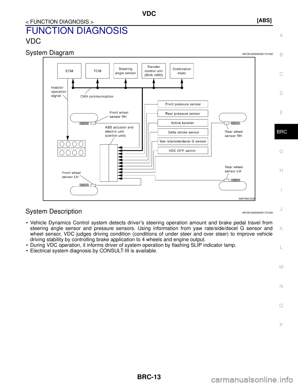
Vehicle Dynamics Control system detects driver′s steering operation amount and brake pedal travel from
steering angle sensor and pressure sensors. Using information from yaw rate/side/decel G sensor and
wheel sensor, VDC judges driving condition (conditions of under steer and over steer) to improve vehicle
driving stability by controlling brake application to 4 wheels and engine output.
During VDC operation, it informs driver of system operation by flashing SLIP indicator lamp.
Electrical system diagnosis by CONSULT-III is available.
AWFIA0012GB
Page 259 of 5883
BRC-26
< FUNCTION DIAGNOSIS >[ABS]
DIAGNOSIS SYSTEM [ABS ACTUATOR AND ELECTRIC UNIT (CONTROL
UNIT)]
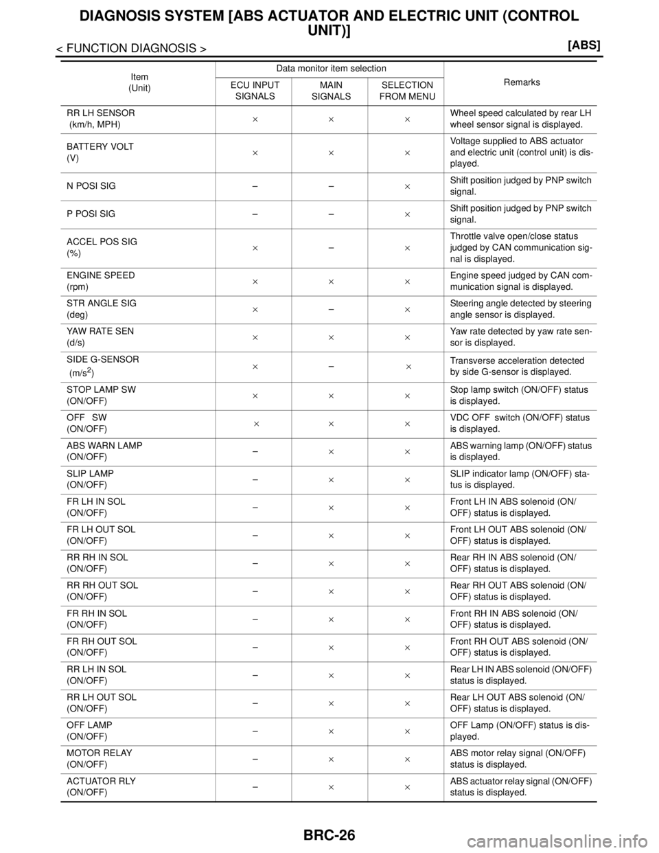
RR LH SENSOR
(km/h, MPH)×××Wheel speed calculated by rear LH
wheel sensor signal is displayed.
BATTERY VOLT
(V)×××Voltage supplied to ABS actuator
and electric unit (control unit) is dis-
played.
N POSI SIG – –×Shift position judged by PNP switch
signal.
P POSI SIG – –×Shift position judged by PNP switch
signal.
ACCEL POS SIG
(%)×–×Throttle valve open/close status
judged by CAN communication sig-
nal is displayed.
ENGINE SPEED
(rpm)×××Engine speed judged by CAN com-
munication signal is displayed.
STR ANGLE SIG
(deg)×–×Steering angle detected by steering
angle sensor is displayed.
YAW RATE SEN
(d/s)×××Yaw rate detected by yaw rate sen-
sor is displayed.
SIDE G-SENSOR
(m/s
2)×– ×Transverse acceleration detected
by side G-sensor is displayed.
STOP LAMP SW
(ON/OFF)×××Stop lamp switch (ON/OFF) status
is displayed.
OFF SW
(ON/OFF) ×× ×VDC OFF switch (ON/OFF) status
is displayed.
ABS WARN LAMP
(ON/OFF)–××ABS warning lamp (ON/OFF) status
is displayed.
SLIP LAMP
(ON/OFF)–××SLIP indicator lamp (ON/OFF) sta-
tus is displayed.
FR LH IN SOL
(ON/OFF)–××Front LH IN ABS solenoid (ON/
OFF) status is displayed.
FR LH OUT SOL
(ON/OFF)–××Front LH OUT ABS solenoid (ON/
OFF) status is displayed.
RR RH IN SOL
(ON/OFF)–××Rear RH IN ABS solenoid (ON/
OFF) status is displayed.
RR RH OUT SOL
(ON/OFF) –××Rear RH OUT ABS solenoid (ON/
OFF) status is displayed.
FR RH IN SOL
(ON/OFF)–××Front RH IN ABS solenoid (ON/
OFF) status is displayed.
FR RH OUT SOL
(ON/OFF)–××Front RH OUT ABS solenoid (ON/
OFF) status is displayed.
RR LH IN SOL
(ON/OFF)–××Rear LH IN ABS solenoid (ON/OFF)
status is displayed.
RR LH OUT SOL
(ON/OFF)–××Rear LH OUT ABS solenoid (ON/
OFF) status is displayed.
OFF LAMP
(ON/OFF)–××OFF Lamp (ON/OFF) status is dis-
played.
MOTOR RELAY
(ON/OFF)–××ABS motor relay signal (ON/OFF)
status is displayed.
ACTUATOR RLY
(ON/OFF)– ××ABS actuator relay signal (ON/OFF)
status is displayed. Item
(Unit)Data monitor item selection
Remarks
ECU INPUT
SIGNALS
MAIN
SIGNALSSELECTION
FROM MENU
Page 270 of 5883
C1109 POWER AND GROUND SYSTEM
BRC-37
< COMPONENT DIAGNOSIS >[ABS]
C
D
E
G
H
I
J
K
L
MA
B
BRC
N
O
P
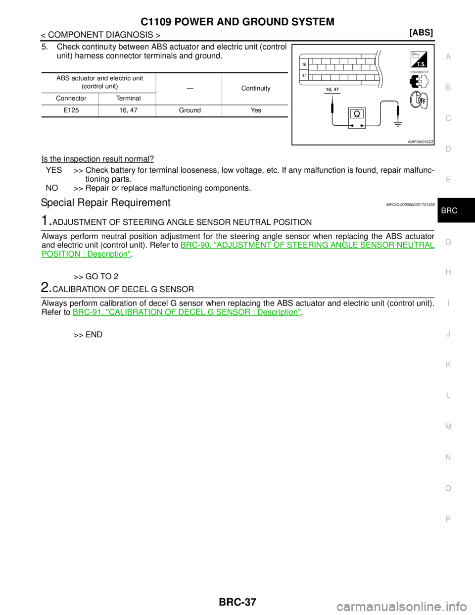
5. Check continuity between ABS actuator and electric unit (control
unit) harness connector terminals and ground.
Is the inspection result normal?
YES >> Check battery for terminal looseness, low voltage, etc. If any malfunction is found, repair malfunc-
tioning parts.
NO >> Repair or replace malfunctioning components.
Special Repair RequirementINFOID:0000000001731238
1.ADJUSTMENT OF STEERING ANGLE SENSOR NEUTRAL POSITION
Always perform neutral position adjustment for the steering angle sensor when replacing the ABS actuator
and electric unit (control unit). Refer to BRC-90, "
ADJUSTMENT OF STEERING ANGLE SENSOR NEUTRAL
POSITION : Description".
>> GO TO 2
2.CALIBRATION OF DECEL G SENSOR
Always perform calibration of decel G sensor when replacing the ABS actuator and electric unit (control unit).
Refer to BRC-91, "
CALIBRATION OF DECEL G SENSOR : Description".
>> END
ABS actuator and electric unit
(control unit)
—Continuity
Connector Terminal
E125 16, 47 Ground Yes
AWFIA0016ZZ
Page 273 of 5883
BRC-40
< COMPONENT DIAGNOSIS >[ABS]
C1111 ABS MOTOR, MOTOR RELAY SYSTEM
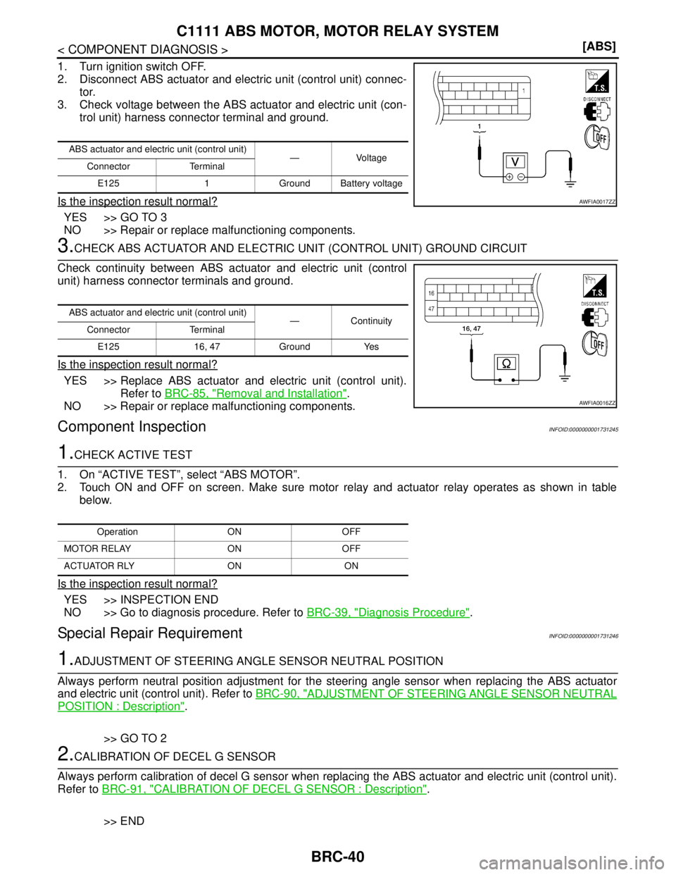
1. Turn ignition switch OFF.
2. Disconnect ABS actuator and electric unit (control unit) connec-
tor.
3. Check voltage between the ABS actuator and electric unit (con-
trol unit) harness connector terminal and ground.
Is the inspection result normal?
YES >> GO TO 3
NO >> Repair or replace malfunctioning components.
3.CHECK ABS ACTUATOR AND ELECTRIC UNIT (CONTROL UNIT) GROUND CIRCUIT
Check continuity between ABS actuator and electric unit (control
unit) harness connector terminals and ground.
Is the inspection result normal?
YES >> Replace ABS actuator and electric unit (control unit).
Refer to BRC-85, "
Removal and Installation".
NO >> Repair or replace malfunctioning components.
Component InspectionINFOID:0000000001731245
1.CHECK ACTIVE TEST
1. On “ACTIVE TEST”, select “ABS MOTOR”.
2. Touch ON and OFF on screen. Make sure motor relay and actuator relay operates as shown in table
below.
Is the inspection result normal?
YES >> INSPECTION END
NO >> Go to diagnosis procedure. Refer to BRC-39, "
Diagnosis Procedure".
Special Repair RequirementINFOID:0000000001731246
1.ADJUSTMENT OF STEERING ANGLE SENSOR NEUTRAL POSITION
Always perform neutral position adjustment for the steering angle sensor when replacing the ABS actuator
and electric unit (control unit). Refer to BRC-90, "
ADJUSTMENT OF STEERING ANGLE SENSOR NEUTRAL
POSITION : Description".
>> GO TO 2
2.CALIBRATION OF DECEL G SENSOR
Always perform calibration of decel G sensor when replacing the ABS actuator and electric unit (control unit).
Refer to BRC-91, "
CALIBRATION OF DECEL G SENSOR : Description".
>> END
ABS actuator and electric unit (control unit)
—Voltage
Connector Terminal
E125 1 Ground Battery voltage
AWFIA0017ZZ
ABS actuator and electric unit (control unit)
— Continuity
Connector Terminal
E125 16, 47 Ground Yes
AWFIA0016ZZ
Operation ON OFF
MOTOR RELAY ON OFF
ACTUATOR RLY ON ON
Page 285 of 5883
BRC-52
< COMPONENT DIAGNOSIS >[ABS]
C1130, C1131, C1132, C1133, C1136 ENGINE SIGNAL
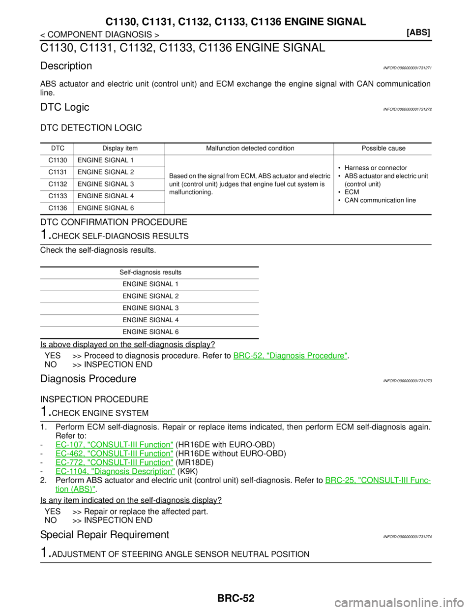
C1130, C1131, C1132, C1133, C1136 ENGINE SIGNAL
DescriptionINFOID:0000000001731271
ABS actuator and electric unit (control unit) and ECM exchange the engine signal with CAN communication
line.
DTC LogicINFOID:0000000001731272
DTC DETECTION LOGIC
DTC CONFIRMATION PROCEDURE
1.CHECK SELF-DIAGNOSIS RESULTS
Check the self-diagnosis results.
Is above displayed on the self-diagnosis display?
YES >> Proceed to diagnosis procedure. Refer to BRC-52, "Diagnosis Procedure".
NO >> INSPECTION END
Diagnosis ProcedureINFOID:0000000001731273
INSPECTION PROCEDURE
1.CHECK ENGINE SYSTEM
1. Perform ECM self-diagnosis. Repair or replace items indicated, then perform ECM self-diagnosis again.
Refer to:
-EC-107, "
CONSULT-III Function" (HR16DE with EURO-OBD)
-EC-462, "
CONSULT-III Function" (HR16DE without EURO-OBD)
-EC-772, "
CONSULT-III Function" (MR18DE)
-EC-1104, "
Diagnosis Description" (K9K)
2. Perform ABS actuator and electric unit (control unit) self-diagnosis. Refer to BRC-25, "
CONSULT-III Func-
tion (ABS)".
Is any item indicated on the self-diagnosis display?
YES >> Repair or replace the affected part.
NO >> INSPECTION END
Special Repair RequirementINFOID:0000000001731274
1.ADJUSTMENT OF STEERING ANGLE SENSOR NEUTRAL POSITION
DTC Display item Malfunction detected condition Possible cause
C1130 ENGINE SIGNAL 1
Based on the signal from ECM, ABS actuator and electric
unit (control unit) judges that engine fuel cut system is
malfunctioning. Harness or connector
ABS actuator and electric unit
(control unit)
ECM
CAN communication line C1131 ENGINE SIGNAL 2
C1132 ENGINE SIGNAL 3
C1133 ENGINE SIGNAL 4
C1136 ENGINE SIGNAL 6
Self-diagnosis results
ENGINE SIGNAL 1
ENGINE SIGNAL 2
ENGINE SIGNAL 3
ENGINE SIGNAL 4
ENGINE SIGNAL 6
Page 313 of 5883
BRC-80
< PRECAUTION >[ABS]
PRECAUTIONS
PRECAUTION
PRECAUTIONS
Precaution for Supplemental Restraint System (SRS) "AIR BAG" and "SEAT BELT
PRE-TENSIONER"
INFOID:0000000001691368
The Supplemental Restraint System such as “AIR BAG” and “SEAT BELT PRE-TENSIONER”, used along
with a front seat belt, helps to reduce the risk or severity of injury to the driver and front passenger for certain
types of collision. Information necessary to service the system safely is included in the SRS and SB section of
this Service Manual.
WARNING:
To avoid rendering the SRS inoperative, which could increase the risk of personal injury or death in
the event of a collision which would result in air bag inflation, all maintenance must be performed by
an authorized NISSAN/INFINITI dealer.
Improper maintenance, including incorrect removal and installation of the SRS, can lead to personal
injury caused by unintentional activation of the system. For removal of Spiral Cable and Air Bag
Module, see the SRS section.
Do not use electrical test equipment on any circuit related to the SRS unless instructed to in this
Service Manual. SRS wiring harnesses can be identified by yellow and/or orange harness connec-
tors.
Precaution for Brake SystemINFOID:0000000001691369
Recommended fluid is Genuine NISSAN Fluid, DOT 3 or DOT 4 (US FMVSS No. 116).
Do not reuse the drained brake fluid.
Be careful not to splash brake fluid on painted areas such as body. If brake fluid is splashed, wipe it off and
flush area with water immediately.
Do not use mineral oils such as gasoline or kerosene to clean. They will ruin rubber parts and cause
improper operation.
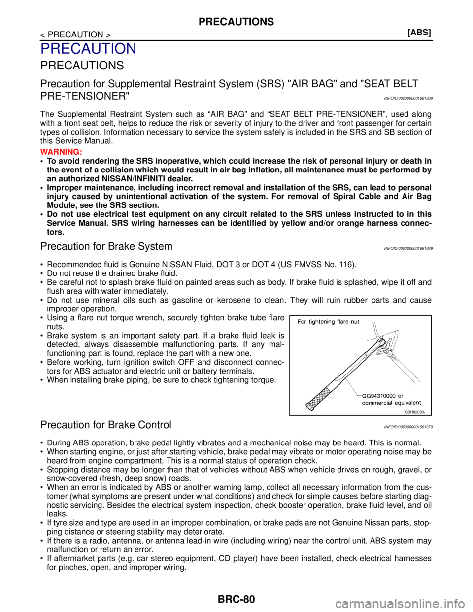
Using a flare nut torque wrench, securely tighten brake tube flare
nuts.
Brake system is an important safety part. If a brake fluid leak is
detected, always disassemble malfunctioning parts. If any mal-
functioning part is found, replace the part with a new one.
Before working, turn ignition switch OFF and disconnect connec-
tors for ABS actuator and electric unit or battery terminals.
When installing brake piping, be sure to check tightening torque.
Precaution for Brake ControlINFOID:0000000001691370
During ABS operation, brake pedal lightly vibrates and a mechanical noise may be heard. This is normal.
When starting engine, or just after starting vehicle, brake pedal may vibrate or motor operating noise may be
heard from engine compartment. This is a normal status of operation check.
Stopping distance may be longer than that of vehicles without ABS when vehicle drives on rough, gravel, or
snow-covered (fresh, deep snow) roads.
When an error is indicated by ABS or another warning lamp, collect all necessary information from the cus-
tomer (what symptoms are present under what conditions) and check for simple causes before starting diag-
nostic servicing. Besides the electrical system inspection, check booster operation, brake fluid level, and oil
leaks.
If tyre size and type are used in an improper combination, or brake pads are not Genuine Nissan parts, stop-
ping distance or steering stability may deteriorate.
If there is a radio, antenna, or antenna lead-in wire (including wiring) near the control unit, ABS system may
malfunction or return an error.
If aftermarket parts (e.g. car stereo equipment, CD player) have been installed, check electrical harnesses
for pinches, open, and improper wiring.
SBR820BA