ECO NISSAN TIIDA 2007 Service Repair Manual
[x] Cancel search | Manufacturer: NISSAN, Model Year: 2007, Model line: TIIDA, Model: NISSAN TIIDA 2007Pages: 5883, PDF Size: 78.95 MB
Page 5131 of 5883
ROAD TEST
TM-185
< ON-VEHICLE MAINTENANCE >[TYPE 1 (4AT: RE4F03B)]
C
E
F
G
H
I
J
K
L
MA
B
TM
N
O
P
When lock-up duty becomes 94%. Refer to XX-XX, "*****".
Does A/T hold lock-up condition for more than 30 seconds?
YES >> GO TO 7.
NO >> Mark the box on the XX-XX, "*****"
.
GO TO TM-151, "
A/T Does Not Hold Lock-up Condition".
Continue “Road Test”.
7.CHECK SHIFT-DOWN (D4L/U TO D4)
Release accelerator pedal.
When lock-up duty becomes 4%. Refer to XX-XX, "*****"
.
Is lock-up released when accelerator pedal is released?
YES >> GO TO 8.
NO >> Mark the box on the XX-XX, "*****"
.
GO TO TM-152, "
Lock-up Is Not Released".
Continue “Road Test”.
8.CHECK SHIFT-DOWN (D4 TO D3)
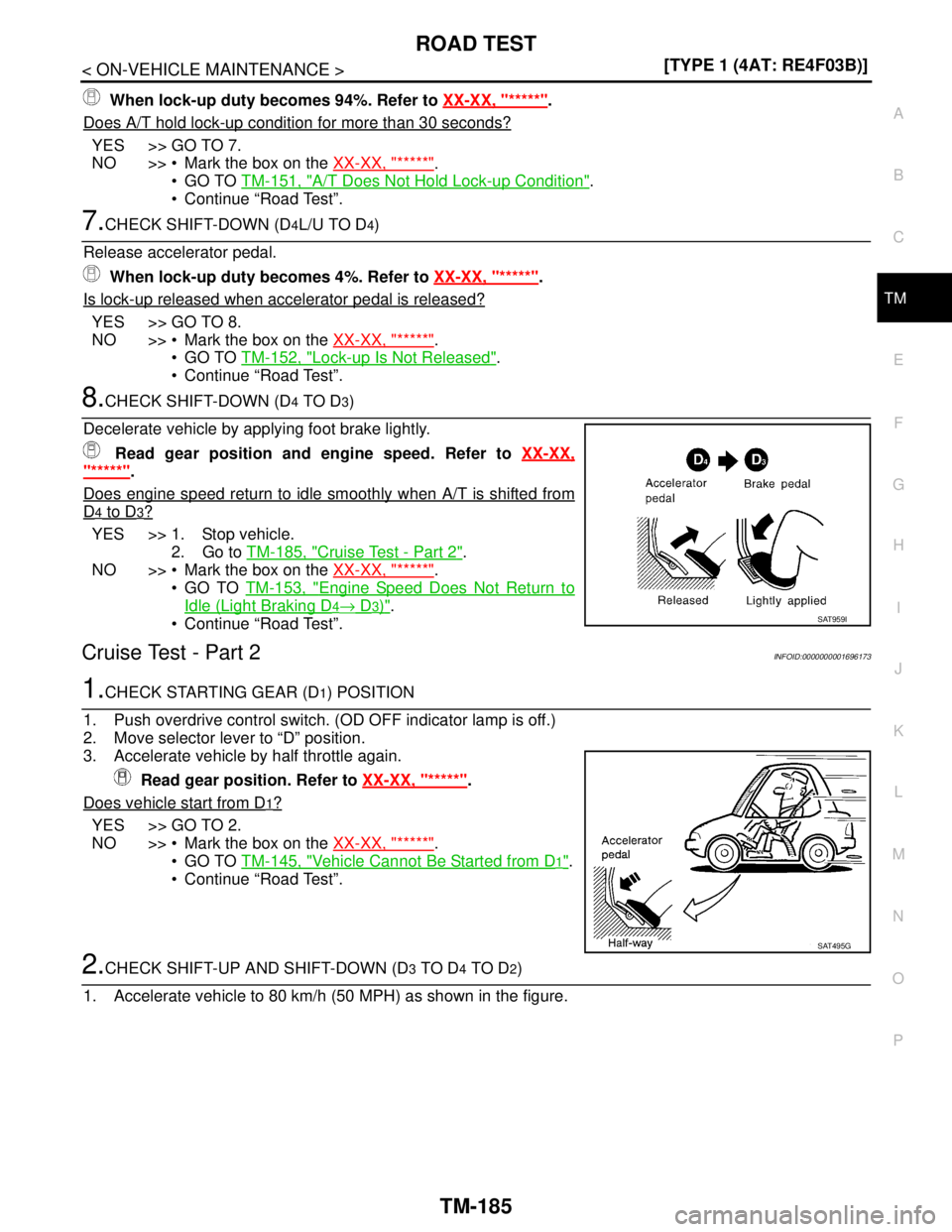
Decelerate vehicle by applying foot brake lightly.
Read gear position and engine speed. Refer to XX-XX,
"*****".
Does engine speed return to idle smoothly when A/T is shifted from
D4 to D3?
YES >> 1. Stop vehicle.
2. Go to TM-185, "
Cruise Test - Part 2".
NO >> Mark the box on the XX-XX, "*****"
.
GO TO TM-153, "
Engine Speed Does Not Return to
Idle (Light Braking D4→ D3)".
Continue “Road Test”.
Cruise Test - Part 2INFOID:0000000001696173
1.CHECK STARTING GEAR (D1) POSITION
1. Push overdrive control switch. (OD OFF indicator lamp is off.)
2. Move selector lever to “D” position.
3. Accelerate vehicle by half throttle again.
Read gear position. Refer to XX-XX, "*****"
.
Does vehicle start from D
1?
YES >> GO TO 2.
NO >> Mark the box on the XX-XX, "*****"
.
GO TO TM-145, "
Vehicle Cannot Be Started from D1".
Continue “Road Test”.
2.CHECK SHIFT-UP AND SHIFT-DOWN (D3 TO D4 TO D2)
1. Accelerate vehicle to 80 km/h (50 MPH) as shown in the figure.
SAT959I
SAT495G
Page 5265 of 5883
SERVICE DATA AND SPECIFICATIONS (SDS)
TM-319
< SERVICE DATA AND SPECIFICATIONS (SDS) [TYPE 1 (4AT: RE4F03B)]
C
E
F
G
H
I
J
K
L
MA
B
TM
N
O
P
SERVICE DATA AND SPECIFICATIONS (SDS)
SERVICE DATA AND SPECIFICATIONS (SDS)
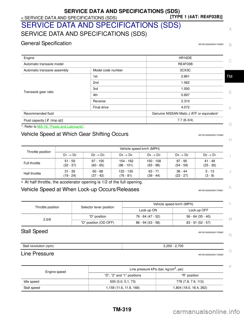
General SpecificationINFOID:0000000001730959
*: Refer to MA-19, "Fluids and Lubricants".
Vehicle Speed at Which Gear Shifting OccursINFOID:0000000001730960
At half throttle, the accelerator opening is 1/2 of the full opening.
Vehicle Speed at When Lock-up Occurs/ReleasesINFOID:0000000001730961
Stall SpeedINFOID:0000000001730962
Line PressureINFOID:0000000001730963
EngineHR16DE
Automatic transaxle modelRE4F03B
Automatic transaxle assembly Model code number 3CX3C
Transaxle gear ratio1st 2.861
2nd 1.562
3rd 1.000
4th 0.697
Reverse 2.310
Final drive 4.072
Recommended fluid Genuine NISSAN Matic J ATF or equivalent
*
Fluid capacity [ (Imp qt)]7.7 (6-3/4)
Throttle positionVehicle speed km/h (MPH)
D1 → D2D2 → D3D3 → D4D4 → D3D3 → D2D2 → D1
Full throttle51 - 59
(32 - 37)97 - 105
(60 - 65) 154 - 162
(96 - 101)150 - 158
(93 - 98)87 - 95
(54 - 59)41 - 49
(25 - 30)
Half throttle31 - 39
(19 - 24)60 - 68
(37 - 42)122 - 130
(76 - 81)63 - 71
(39 - 44)36 - 44
(22 - 27)5 - 13
(3 - 8)
Throttle position Selector lever positionVehicle speed km/h (MPH)
Lock-up ON Lock-up OFF
2.0/8“D” position 76 - 84 (47 - 52) 56 - 64 (35 - 40)
“D” position (OD OFF) 86 - 94 (53 - 58) 83 - 91 (52 - 57)
Stall revolution (rpm)2,250 - 2,700
Engine speedLine pressure kPa (bar, kg/cm
2, psi)
“D”, “2” and “1” positions “R” position
Idle speed 500 (5.0, 5.1, 73) 778 (7.8, 7.9, 113)
Stall speed 1,159 (11.6, 11.8, 168) 1,804 (18.0, 18.4, 262)
Page 5286 of 5883
TM-340
< FUNCTION DIAGNOSIS >[TYPE 2 (4AT: RE4F03B)]
A/T CONTROL SYSTEM
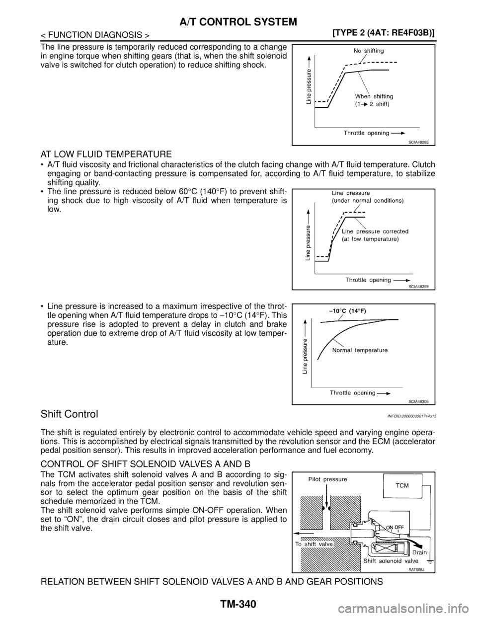
The line pressure is temporarily reduced corresponding to a change
in engine torque when shifting gears (that is, when the shift solenoid
valve is switched for clutch operation) to reduce shifting shock.
AT LOW FLUID TEMPERATURE
A/T fluid viscosity and frictional characteristics of the clutch facing change with A/T fluid temperature. Clutch
engaging or band-contacting pressure is compensated for, according to A/T fluid temperature, to stabilize
shifting quality.
The line pressure is reduced below 60°C (140°F) to prevent shift-
ing shock due to high viscosity of A/T fluid when temperature is
low.
Line pressure is increased to a maximum irrespective of the throt-
tle opening when A/T fluid temperature drops to −10°C (14°F). This
pressure rise is adopted to prevent a delay in clutch and brake
operation due to extreme drop of A/T fluid viscosity at low temper-
ature.
Shift ControlINFOID:0000000001714315
The shift is regulated entirely by electronic control to accommodate vehicle speed and varying engine opera-
tions. This is accomplished by electrical signals transmitted by the revolution sensor and the ECM (accelerator
pedal position sensor). This results in improved acceleration performance and fuel economy.
CONTROL OF SHIFT SOLENOID VALVES A AND B
The TCM activates shift solenoid valves A and B according to sig-
nals from the accelerator pedal position sensor and revolution sen-
sor to select the optimum gear position on the basis of the shift
schedule memorized in the TCM.
The shift solenoid valve performs simple ON-OFF operation. When
set to “ON”, the drain circuit closes and pilot pressure is applied to
the shift valve.
RELATION BETWEEN SHIFT SOLENOID VALVES A AND B AND GEAR POSITIONS
SCIA4828E
SCIA4829E
SCIA4830E
SAT008J
Page 5289 of 5883
A/T CONTROL SYSTEM
TM-343
< FUNCTION DIAGNOSIS >[TYPE 2 (4AT: RE4F03B)]
C
E
F
G
H
I
J
K
L
MA
B
TM
N
O
P
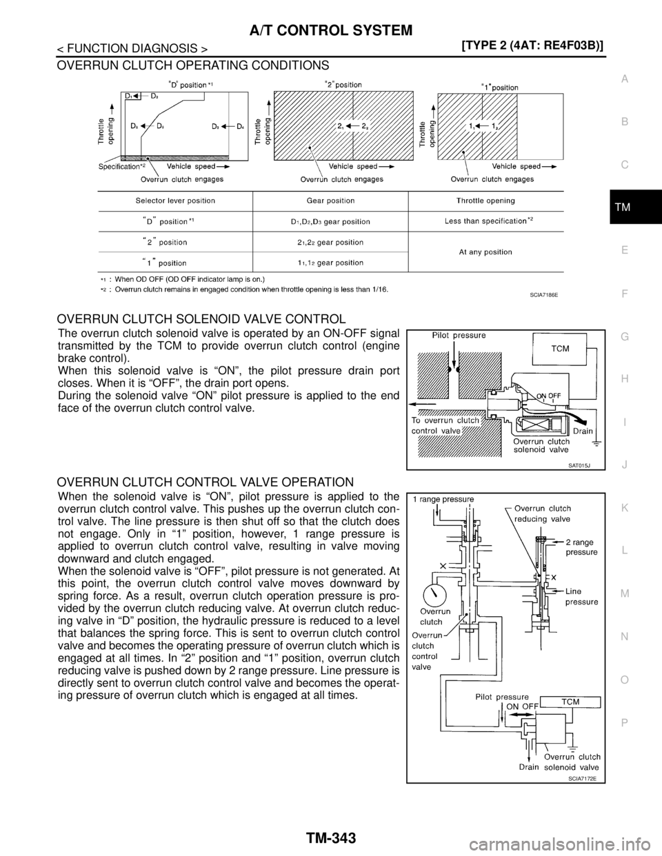
OVERRUN CLUTCH OPERATING CONDITIONS
OVERRUN CLUTCH SOLENOID VALVE CONTROL
The overrun clutch solenoid valve is operated by an ON-OFF signal
transmitted by the TCM to provide overrun clutch control (engine
brake control).
When this solenoid valve is “ON”, the pilot pressure drain port
closes. When it is “OFF”, the drain port opens.
During the solenoid valve “ON” pilot pressure is applied to the end
face of the overrun clutch control valve.
OVERRUN CLUTCH CONTROL VALVE OPERATION
When the solenoid valve is “ON”, pilot pressure is applied to the
overrun clutch control valve. This pushes up the overrun clutch con-
trol valve. The line pressure is then shut off so that the clutch does
not engage. Only in “1” position, however, 1 range pressure is
applied to overrun clutch control valve, resulting in valve moving
downward and clutch engaged.
When the solenoid valve is “OFF”, pilot pressure is not generated. At
this point, the overrun clutch control valve moves downward by
spring force. As a result, overrun clutch operation pressure is pro-
vided by the overrun clutch reducing valve. At overrun clutch reduc-
ing valve in “D” position, the hydraulic pressure is reduced to a level
that balances the spring force. This is sent to overrun clutch control
valve and becomes the operating pressure of overrun clutch which is
engaged at all times. In “2” position and “1” position, overrun clutch
reducing valve is pushed down by 2 range pressure. Line pressure is
directly sent to overrun clutch control valve and becomes the operat-
ing pressure of overrun clutch which is engaged at all times.
SCIA7186E
SAT015J
SCIA7172E
Page 5295 of 5883
DIAGNOSIS SYSTEM (TCM)
TM-349
< FUNCTION DIAGNOSIS >[TYPE 2 (4AT: RE4F03B)]
C
E
F
G
H
I
J
K
L
MA
B
TM
N
O
P
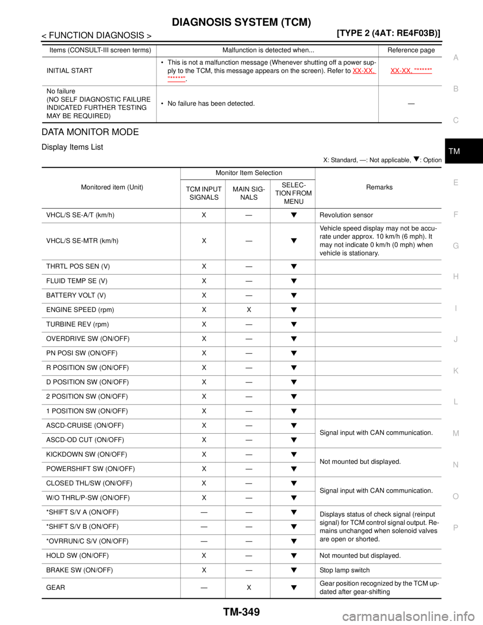
DATA MONITOR MODE
Display Items List
X: Standard, —: Not applicable, : Option
INITIAL START This is not a malfunction message (Whenever shutting off a power sup-
ply to the TCM, this message appears on the screen). Refer to XX-XX,
"*****".XX-XX, "*****"
No failure
(NO SELF DIAGNOSTIC FAILURE
INDICATED FURTHER TESTING
MAY BE REQUIRED) No failure has been detected. — Items (CONSULT-III screen terms) Malfunction is detected when... Reference page
Monitored item (Unit)Monitor Item Selection
Remarks
TCM INPUT
SIGNALSMAIN SIG-
NALSSELEC-
TION FROM
MENU
VHCL/S SE-A/T (km/h) X — Revolution sensor
VHCL/S SE-MTR (km/h) X —Vehicle speed display may not be accu-
rate under approx. 10 km/h (6 mph). It
may not indicate 0 km/h (0 mph) when
vehicle is stationary.
THRTL POS SEN (V) X —
FLUID TEMP SE (V) X —
BATTERY VOLT (V) X —
ENGINE SPEED (rpm) X X
TURBINE REV (rpm) X —
OVERDRIVE SW (ON/OFF) X —
PN POSI SW (ON/OFF) X —
R POSITION SW (ON/OFF) X —
D POSITION SW (ON/OFF) X —
2 POSITION SW (ON/OFF) X —
1 POSITION SW (ON/OFF) X —
ASCD-CRUISE (ON/OFF) X —
Signal input with CAN communication.
ASCD-OD CUT (ON/OFF) X —
KICKDOWN SW (ON/OFF) X —
Not mounted but displayed.
POWERSHIFT SW (ON/OFF) X —
CLOSED THL/SW (ON/OFF) X —
Signal input with CAN communication.
W/O THRL/P-SW (ON/OFF) X —
*SHIFT S/V A (ON/OFF) — —
Displays status of check signal (reinput
signal) for TCM control signal output. Re-
mains unchanged when solenoid valves
are open or shorted. *SHIFT S/V B (ON/OFF) — —
*OVRRUN/C S/V (ON/OFF) — —
HOLD SW (ON/OFF) X — Not mounted but displayed.
BRAKE SW (ON/OFF) X — Stop lamp switch
GEAR — XGear position recognized by the TCM up-
dated after gear-shifting
Page 5296 of 5883
TM-350
< FUNCTION DIAGNOSIS >[TYPE 2 (4AT: RE4F03B)]
DIAGNOSIS SYSTEM (TCM)
Diagnosis Procedure without CONSULT-III
INFOID:0000000001714330
TCM SELF-DIAGNOSTIC PROCEDURE
Description
If a malfunction occurs in electrical system, turning ignition switch ON will illuminate OD OFF indicator lamp for
2 seconds. To detect a malfunction, entering a self-diagnosis start signal retrieves information on malfunctions
from memory and indicates malfunction by blinking OD OFF indicator lamp.
Diagnostic Procedure
1.CHECK OD OFF INDICATOR LAMP
1. Park vehicle on flat surface.
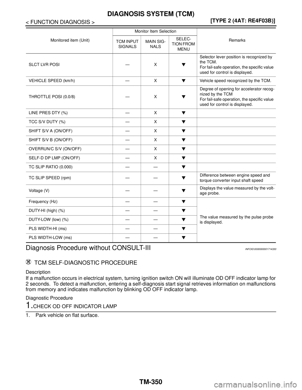
SLCT LVR POSI — XSelector lever position is recognized by
the TCM.
For fail-safe operation, the specific value
used for control is displayed.
VEHICLE SPEED (km/h) — X Vehicle speed recognized by the TCM.
THROTTLE POSI (0.0/8) — XDegree of opening for accelerator recog-
nized by the TCM
For fail-safe operation, the specific value
used for control is displayed.
LINE PRES DTY (%) — X
TCC S/V DUTY (%) — X
SHIFT S/V A (ON/OFF) — X
SHIFT S/V B (ON/OFF) — X
OVERRUN/C S/V (ON/OFF) — X
SELF-D DP LMP (ON/OFF) — X
TC SLIP RATIO (0.000) — —
TC SLIP SPEED (rpm) — —Difference between engine speed and
torque converter input shaft speed
Voltage (V) — —Displays the value measured by the volt-
age probe.
Frequency (Hz) — —
The value measured by the pulse probe
is displayed. DUTY-HI (high) (%) — —
DUTY-LOW (low) (%) — —
PLS WIDTH-HI (ms) — —
PLS WIDTH-LOW (ms) — —Monitored item (Unit)Monitor Item Selection
Remarks
TCM INPUT
SIGNALSMAIN SIG-
NALSSELEC-
TION FROM
MENU
Page 5297 of 5883
DIAGNOSIS SYSTEM (TCM)
TM-351
< FUNCTION DIAGNOSIS >[TYPE 2 (4AT: RE4F03B)]
C
E
F
G
H
I
J
K
L
MA
B
TM
N
O
P
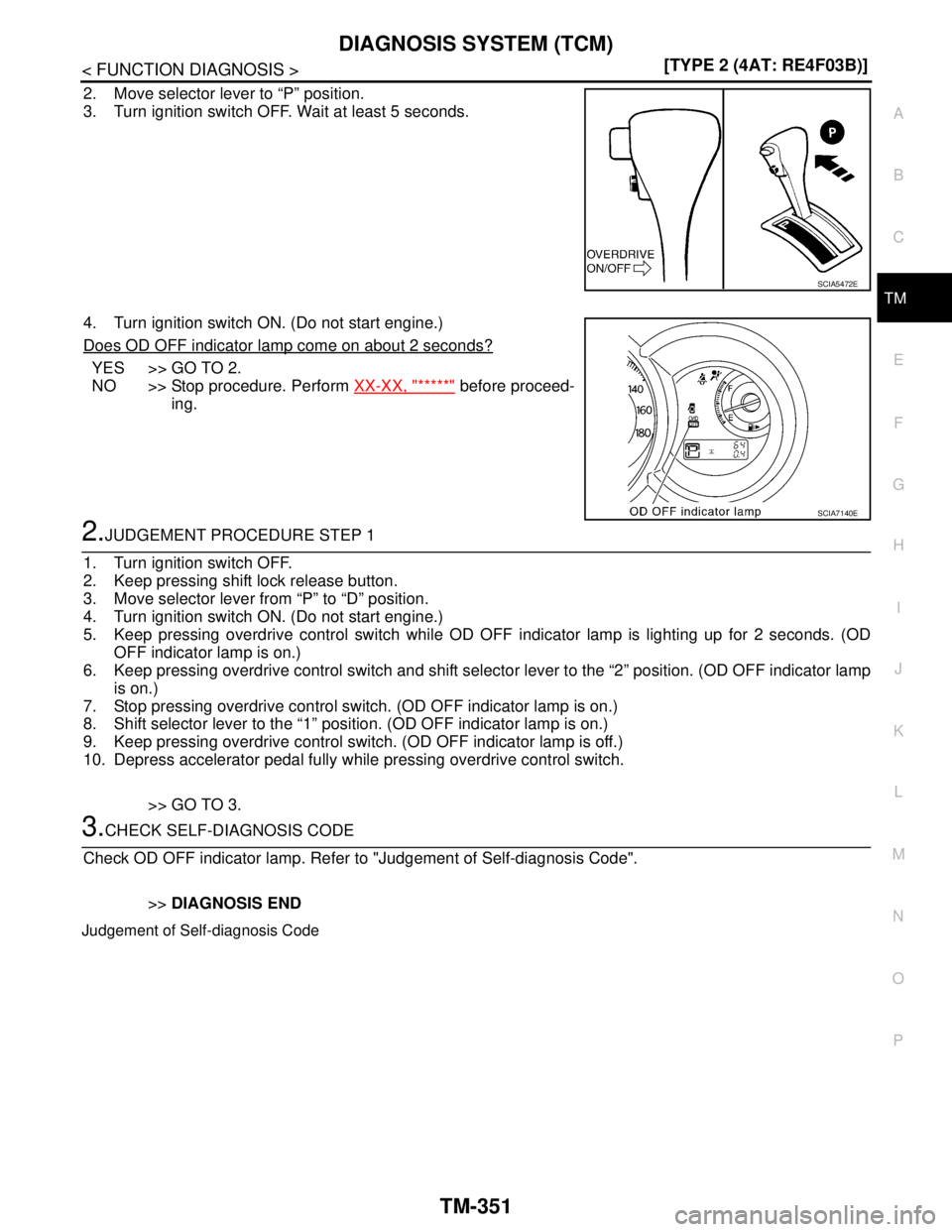
2. Move selector lever to “P” position.
3. Turn ignition switch OFF. Wait at least 5 seconds.
4. Turn ignition switch ON. (Do not start engine.)
Does OD OFF indicator lamp come on about 2 seconds?
YES >> GO TO 2.
NO >> Stop procedure. Perform XX-XX, "*****"
before proceed-
ing.
2.JUDGEMENT PROCEDURE STEP 1
1. Turn ignition switch OFF.
2. Keep pressing shift lock release button.
3. Move selector lever from “P” to “D” position.
4. Turn ignition switch ON. (Do not start engine.)
5. Keep pressing overdrive control switch while OD OFF indicator lamp is lighting up for 2 seconds. (OD
OFF indicator lamp is on.)
6. Keep pressing overdrive control switch and shift selector lever to the “2” position. (OD OFF indicator lamp
is on.)
7. Stop pressing overdrive control switch. (OD OFF indicator lamp is on.)
8. Shift selector lever to the “1” position. (OD OFF indicator lamp is on.)
9. Keep pressing overdrive control switch. (OD OFF indicator lamp is off.)
10. Depress accelerator pedal fully while pressing overdrive control switch.
>> GO TO 3.
3.CHECK SELF-DIAGNOSIS CODE
Check OD OFF indicator lamp. Refer to "Judgement of Self-diagnosis Code".
>>DIAGNOSIS END
Judgement of Self-diagnosis Code
SCIA5472E
SCIA7140E
Page 5300 of 5883
TM-354
< FUNCTION DIAGNOSIS >[TYPE 2 (4AT: RE4F03B)]
DIAGNOSIS SYSTEM (TCM)
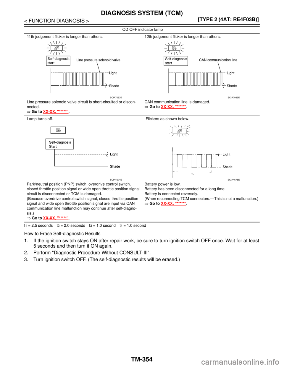
t1 = 2.5 seconds t2 = 2.0 seconds t3 = 1.0 second t4 = 1.0 second
How to Erase Self-diagnostic Results
1. If the ignition switch stays ON after repair work, be sure to turn ignition switch OFF once. Wait for at least
5 seconds and then turn it ON again.
2. Perform "Diagnostic Procedure Without CONSULT-III".
3. Turn ignition switch OFF. (The self-diagnostic results will be erased.)
11th judgement flicker is longer than others.
Line pressure solenoid valve circuit is short-circuited or discon-
nected.
⇒ Go to XX-XX, "*****"
.12th judgement flicker is longer than others.
CAN communication line is damaged.
⇒ Go to XX-XX, "*****"
.
Lamp turns off.
Park/neutral position (PNP) switch, overdrive control switch,
closed throttle position signal or wide open throttle position signal
circuit is disconnected or TCM is damaged.
(Because overdrive control switch signal, closed throttle position
signal and wide open throttle position signal are input via CAN
communication line malfunction may continue after self-diagno-
sis.)
⇒ Go to XX-XX, "*****"
. Flickers as shown below.
Battery power is low.
Battery has been disconnected for a long time.
Battery is connected reversely.
(When reconnecting TCM connectors.—This is not a malfunction.)
⇒ Go to XX-XX, "*****"
. OD OFF indicator lamp
SCIA7083ESCIA7085E
SCIA4674ESCIA4675E
Page 5301 of 5883
VEHICLE SPEED SENSOR - A/T (REVOLUTION SENSOR)
TM-355
< COMPONENT DIAGNOSIS >[TYPE 2 (4AT: RE4F03B)]
C
E
F
G
H
I
J
K
L
MA
B
TM
N
O
P
COMPONENT DIAGNOSIS
VEHICLE SPEED SENSOR - A/T (REVOLUTION SENSOR)
DescriptionINFOID:0000000001712982
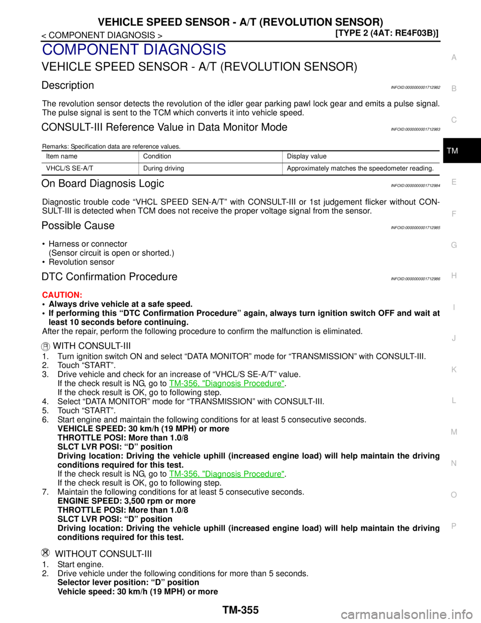
The revolution sensor detects the revolution of the idler gear parking pawl lock gear and emits a pulse signal.
The pulse signal is sent to the TCM which converts it into vehicle speed.
CONSULT-III Reference Value in Data Monitor ModeINFOID:0000000001712983
Remarks: Specification data are reference values.
On Board Diagnosis LogicINFOID:0000000001712984
Diagnostic trouble code “VHCL SPEED SEN-A/T” with CONSULT-III or 1st judgement flicker without CON-
SULT-III is detected when TCM does not receive the proper voltage signal from the sensor.
Possible CauseINFOID:0000000001712985
Harness or connector
(Sensor circuit is open or shorted.)
Revolution sensor
DTC Confirmation ProcedureINFOID:0000000001712986
CAUTION:
Always drive vehicle at a safe speed.
If performing this “DTC Confirmation Procedure” again, always turn ignition switch OFF and wait at
least 10 seconds before continuing.
After the repair, perform the following procedure to confirm the malfunction is eliminated.
WITH CONSULT-III
1. Turn ignition switch ON and select “DATA MONITOR” mode for “TRANSMISSION” with CONSULT-III.
2. Touch “START”.
3. Drive vehicle and check for an increase of “VHCL/S SE-A/T” value.
If the check result is NG, go to TM-356, "
Diagnosis Procedure".
If the check result is OK, go to following step.
4. Select “DATA MONITOR” mode for “TRANSMISSION” with CONSULT-III.
5. Touch “START”.
6. Start engine and maintain the following conditions for at least 5 consecutive seconds.
VEHICLE SPEED: 30 km/h (19 MPH) or more
THROTTLE POSI: More than 1.0/8
SLCT LVR POSI: “D” position
Driving location: Driving the vehicle uphill (increased engine load) will help maintain the driving
conditions required for this test.
If the check result is NG, go to TM-356, "
Diagnosis Procedure".
If the check result is OK, go to following step.
7. Maintain the following conditions for at least 5 consecutive seconds.
ENGINE SPEED: 3,500 rpm or more
THROTTLE POSI: More than 1.0/8
SLCT LVR POSI: “D” position
Driving location: Driving the vehicle uphill (increased engine load) will help maintain the driving
conditions required for this test.
WITHOUT CONSULT-III
1. Start engine.
2. Drive vehicle under the following conditions for more than 5 seconds.
Selector lever position: “D” position
Vehicle speed: 30 km/h (19 MPH) or more
Item name Condition Display value
VHCL/S SE-A/T During driving Approximately matches the speedometer reading.
Page 5305 of 5883
VEHICLE SPEED SENSOR MTR
TM-359
< COMPONENT DIAGNOSIS >[TYPE 2 (4AT: RE4F03B)]
C
E
F
G
H
I
J
K
L
MA
B
TM
N
O
P
VEHICLE SPEED SENSOR MTR
DescriptionINFOID:0000000001712989
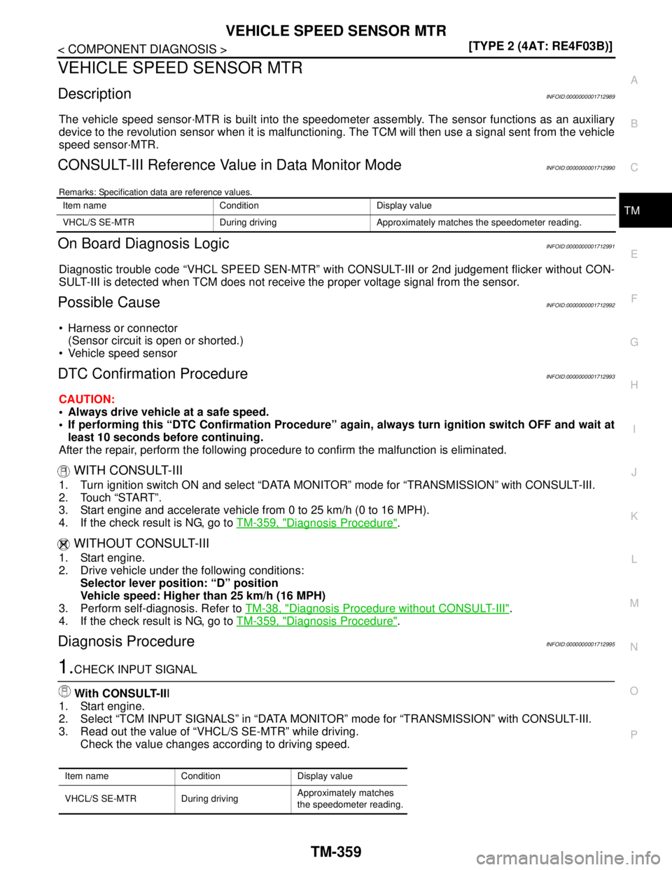
The vehicle speed sensor·MTR is built into the speedometer assembly. The sensor functions as an auxiliary
device to the revolution sensor when it is malfunctioning. The TCM will then use a signal sent from the vehicle
speed sensor·MTR.
CONSULT-III Reference Value in Data Monitor ModeINFOID:0000000001712990
Remarks: Specification data are reference values.
On Board Diagnosis LogicINFOID:0000000001712991
Diagnostic trouble code “VHCL SPEED SEN-MTR” with CONSULT-III or 2nd judgement flicker without CON-
SULT-III is detected when TCM does not receive the proper voltage signal from the sensor.
Possible CauseINFOID:0000000001712992
Harness or connector
(Sensor circuit is open or shorted.)
Vehicle speed sensor
DTC Confirmation ProcedureINFOID:0000000001712993
CAUTION:
Always drive vehicle at a safe speed.
If performing this “DTC Confirmation Procedure” again, always turn ignition switch OFF and wait at
least 10 seconds before continuing.
After the repair, perform the following procedure to confirm the malfunction is eliminated.
WITH CONSULT-III
1. Turn ignition switch ON and select “DATA MONITOR” mode for “TRANSMISSION” with CONSULT-III.
2. Touch “START”.
3. Start engine and accelerate vehicle from 0 to 25 km/h (0 to 16 MPH).
4. If the check result is NG, go to TM-359, "
Diagnosis Procedure".
WITHOUT CONSULT-III
1. Start engine.
2. Drive vehicle under the following conditions:
Selector lever position: “D” position
Vehicle speed: Higher than 25 km/h (16 MPH)
3. Perform self-diagnosis. Refer to TM-38, "
Diagnosis Procedure without CONSULT-III".
4. If the check result is NG, go to TM-359, "
Diagnosis Procedure".
Diagnosis ProcedureINFOID:0000000001712995
1.CHECK INPUT SIGNAL
With CONSULT-III
1. Start engine.
2. Select “TCM INPUT SIGNALS” in “DATA MONITOR” mode for “TRANSMISSION” with CONSULT-III.
3. Read out the value of “VHCL/S SE-MTR” while driving.
Check the value changes according to driving speed.
Item name Condition Display value
VHCL/S SE-MTR During driving Approximately matches the speedometer reading.
Item name Condition Display value
VHCL/S SE-MTR During drivingApproximately matches
the speedometer reading.