ECO NISSAN TIIDA 2007 Service Repair Manual
[x] Cancel search | Manufacturer: NISSAN, Model Year: 2007, Model line: TIIDA, Model: NISSAN TIIDA 2007Pages: 5883, PDF Size: 78.95 MB
Page 5430 of 5883
TM-484
< ON-VEHICLE MAINTENANCE >[TYPE 2 (4AT: RE4F03B)]
ROAD TEST
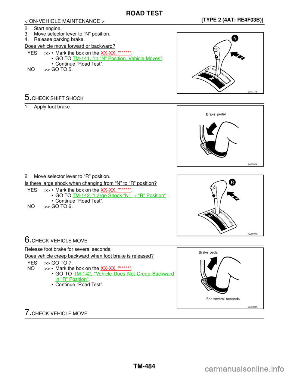
2. Start engine.
3. Move selector lever to “N” position.
4. Release parking brake.
Does vehicle move forward or backward?
YES >> Mark the box on the XX-XX, "*****".
GO TO TM-141, "
In "N" Position, Vehicle Moves".
Continue “Road Test”.
NO >> GO TO 5.
5.CHECK SHIFT SHOCK
1. Apply foot brake.
2. Move selector lever to “R” position.
Is there large shock when changing from
“N” to “R” position?
YES >> Mark the box on the XX-XX, "*****".
GO TO TM-142, "
Large Shock "N" → "R" Position" .
Continue “Road Test”.
NO >> GO TO 6.
6.CHECK VEHICLE MOVE
Release foot brake for several seconds.
Does vehicle creep backward when foot brake is released?
YES >> GO TO 7.
NO >> Mark the box on the XX-XX, "*****"
.
GO TO TM-142, "
Vehicle Does Not Creep Backward
in "R" Position".
Continue “Road Test”.
7.CHECK VEHICLE MOVE
SAT771B
SAT797A
SAT772B
SAT799A
Page 5432 of 5883
TM-486
< ON-VEHICLE MAINTENANCE >[TYPE 2 (4AT: RE4F03B)]
ROAD TEST
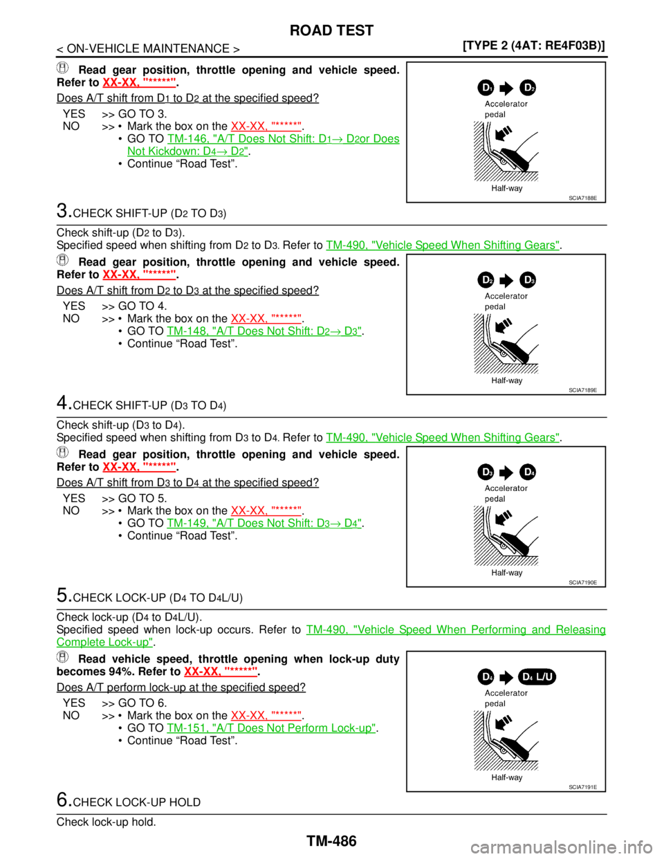
Read gear position, throttle opening and vehicle speed.
Refer to XX-XX, "*****"
.
Does A/T shift from D
1 to D2 at the specified speed?
YES >> GO TO 3.
NO >> Mark the box on the XX-XX, "*****"
.
GO TO TM-146, "
A/T Does Not Shift: D1→ D2or Does
Not Kickdown: D4→ D2".
Continue “Road Test”.
3.CHECK SHIFT-UP (D2 TO D3)
Check shift-up (D
2 to D3).
Specified speed when shifting from D
2 to D3. Refer to TM-490, "Vehicle Speed When Shifting Gears".
Read gear position, throttle opening and vehicle speed.
Refer to XX-XX, "*****"
.
Does A/T shift from D
2 to D3 at the specified speed?
YES >> GO TO 4.
NO >> Mark the box on the XX-XX, "*****"
.
GO TO TM-148, "
A/T Does Not Shift: D2→ D3".
Continue “Road Test”.
4.CHECK SHIFT-UP (D3 TO D4)
Check shift-up (D
3 to D4).
Specified speed when shifting from D
3 to D4. Refer to TM-490, "Vehicle Speed When Shifting Gears".
Read gear position, throttle opening and vehicle speed.
Refer to XX-XX, "*****"
.
Does A/T shift from D
3 to D4 at the specified speed?
YES >> GO TO 5.
NO >> Mark the box on the XX-XX, "*****"
.
GO TO TM-149, "
A/T Does Not Shift: D3→ D4".
Continue “Road Test”.
5.CHECK LOCK-UP (D4 TO D4L/U)
Check lock-up (D
4 to D4L/U).
Specified speed when lock-up occurs. Refer to TM-490, "
Vehicle Speed When Performing and Releasing
Complete Lock-up".
Read vehicle speed, throttle opening when lock-up duty
becomes 94%. Refer to XX-XX, "*****"
.
Does A/T perform lock-up at the specified speed?
YES >> GO TO 6.
NO >> Mark the box on the XX-XX, "*****"
.
GO TO TM-151, "
A/T Does Not Perform Lock-up".
Continue “Road Test”.
6.CHECK LOCK-UP HOLD
Check lock-up hold.
SCIA7188E
SCIA7189E
SCIA7190E
SCIA7191E
Page 5433 of 5883
ROAD TEST
TM-487
< ON-VEHICLE MAINTENANCE >[TYPE 2 (4AT: RE4F03B)]
C
E
F
G
H
I
J
K
L
MA
B
TM
N
O
P
When lock-up duty becomes 94%. Refer to XX-XX, "*****".
Does A/T hold lock-up condition for more than 30 seconds?
YES >> GO TO 7.
NO >> Mark the box on the XX-XX, "*****"
.
GO TO TM-151, "
A/T Does Not Hold Lock-up Condition".
Continue “Road Test”.
7.CHECK SHIFT-DOWN (D4L/U TO D4)
Release accelerator pedal.
When lock-up duty becomes 4%. Refer to XX-XX, "*****"
.
Is lock-up released when accelerator pedal is released?
YES >> GO TO 8.
NO >> Mark the box on the XX-XX, "*****"
.
GO TO TM-152, "
Lock-up Is Not Released".
Continue “Road Test”.
8.CHECK SHIFT-DOWN (D4 TO D3)
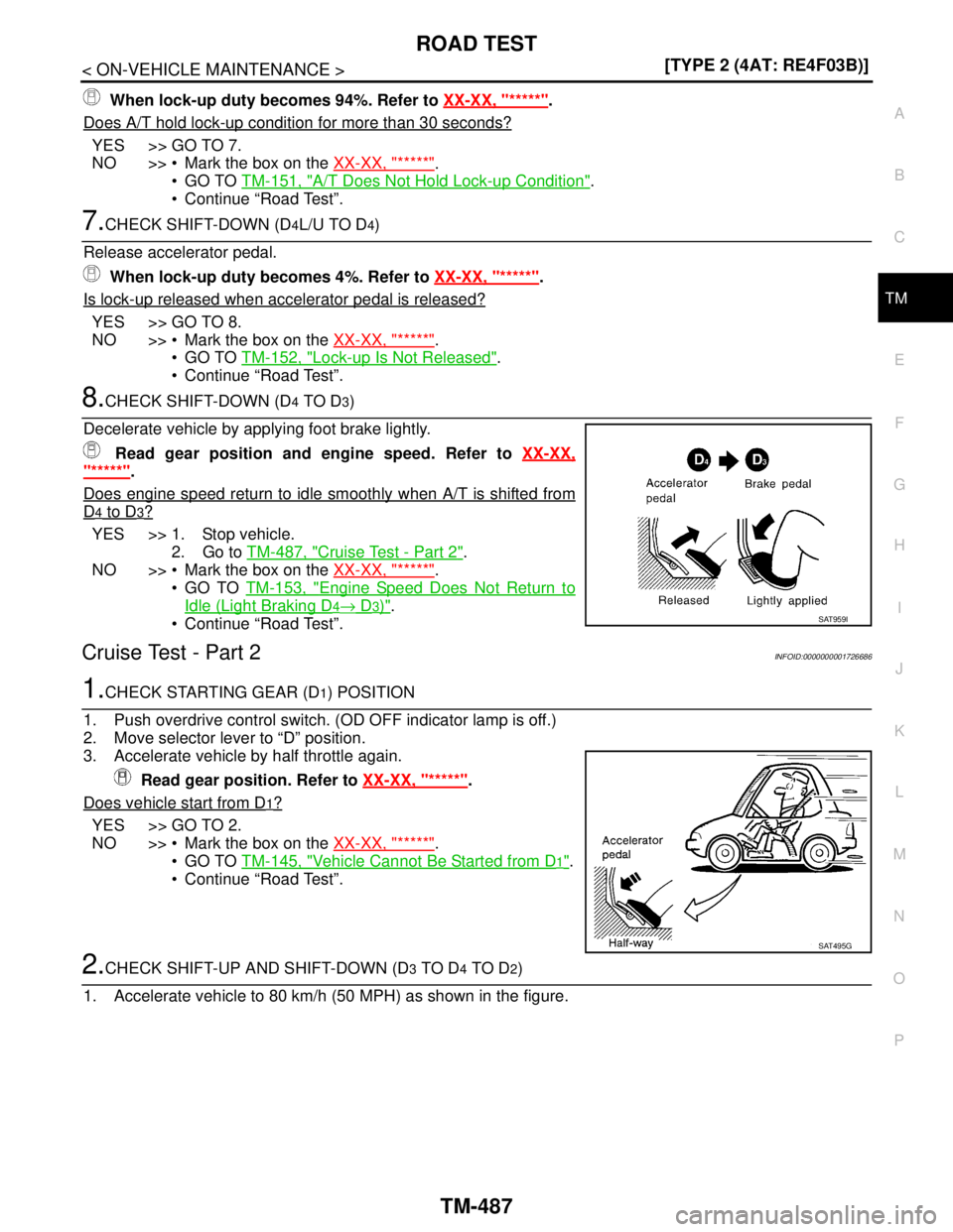
Decelerate vehicle by applying foot brake lightly.
Read gear position and engine speed. Refer to XX-XX,
"*****".
Does engine speed return to idle smoothly when A/T is shifted from
D4 to D3?
YES >> 1. Stop vehicle.
2. Go to TM-487, "
Cruise Test - Part 2".
NO >> Mark the box on the XX-XX, "*****"
.
GO TO TM-153, "
Engine Speed Does Not Return to
Idle (Light Braking D4→ D3)".
Continue “Road Test”.
Cruise Test - Part 2INFOID:0000000001726686
1.CHECK STARTING GEAR (D1) POSITION
1. Push overdrive control switch. (OD OFF indicator lamp is off.)
2. Move selector lever to “D” position.
3. Accelerate vehicle by half throttle again.
Read gear position. Refer to XX-XX, "*****"
.
Does vehicle start from D
1?
YES >> GO TO 2.
NO >> Mark the box on the XX-XX, "*****"
.
GO TO TM-145, "
Vehicle Cannot Be Started from D1".
Continue “Road Test”.
2.CHECK SHIFT-UP AND SHIFT-DOWN (D3 TO D4 TO D2)
1. Accelerate vehicle to 80 km/h (50 MPH) as shown in the figure.
SAT959I
SAT495G
Page 5558 of 5883
TM-612
< SERVICE DATA AND SPECIFICATIONS (SDS) [TYPE 2 (4AT: RE4F03B)]
SERVICE DATA AND SPECIFICATIONS (SDS)
SERVICE DATA AND SPECIFICATIONS (SDS)
SERVICE DATA AND SPECIFICATIONS (SDS)
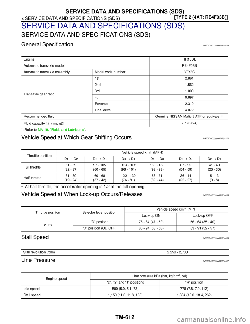
General SpecificationINFOID:0000000001731453
*: Refer to MA-19, "Fluids and Lubricants".
Vehicle Speed at Which Gear Shifting OccursINFOID:0000000001731454
At half throttle, the accelerator opening is 1/2 of the full opening.
Vehicle Speed at When Lock-up Occurs/ReleasesINFOID:0000000001731455
Stall SpeedINFOID:0000000001731456
Line PressureINFOID:0000000001731457
EngineHR16DE
Automatic transaxle modelRE4F03B
Automatic transaxle assembly Model code number 3CX3C
Transaxle gear ratio1st 2.861
2nd 1.562
3rd 1.000
4th 0.697
Reverse 2.310
Final drive 4.072
Recommended fluid Genuine NISSAN Matic J ATF or equivalent
*
Fluid capacity [ (Imp qt)]7.7 (6-3/4)
Throttle positionVehicle speed km/h (MPH)
D1 → D2D2 → D3D3 → D4D4 → D3D3 → D2D2 → D1
Full throttle51 - 59
(32 - 37)97 - 105
(60 - 65) 154 - 162
(96 - 101)150 - 158
(93 - 98)87 - 95
(54 - 59)41 - 49
(25 - 30)
Half throttle31 - 39
(19 - 24)60 - 68
(37 - 42)122 - 130
(76 - 81)63 - 71
(39 - 44)36 - 44
(22 - 27)5 - 13
(3 - 8)
Throttle position Selector lever positionVehicle speed km/h (MPH)
Lock-up ON Lock-up OFF
2.0/8“D” position 76 - 84 (47 - 52) 56 - 64 (35 - 40)
“D” position (OD OFF) 86 - 94 (53 - 58) 83 - 91 (52 - 57)
Stall revolution (rpm)2,250 - 2,700
Engine speedLine pressure kPa (bar, kg/cm
2, psi)
“D”, “2” and “1” positions “R” position
Idle speed 500 (5.0, 5.1, 73) 778 (7.8, 7.9, 113)
Stall speed 1,159 (11.6, 11.8, 168) 1,804 (18.0, 18.4, 262)
Page 5596 of 5883
TM-650
< DISASSEMBLY AND ASSEMBLY >[5MT: RS5F91R]
TRANSAXLE ASSEMBLY
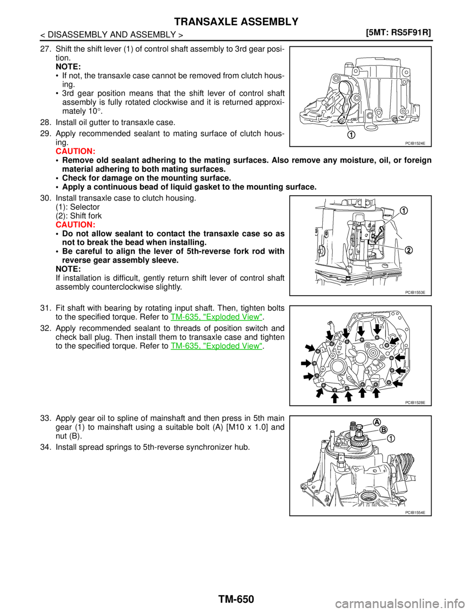
27. Shift the shift lever (1) of control shaft assembly to 3rd gear posi-
tion.
NOTE:
If not, the transaxle case cannot be removed from clutch hous-
ing.
3rd gear position means that the shift lever of control shaft
assembly is fully rotated clockwise and it is returned approxi-
mately 10°.
28. Install oil gutter to transaxle case.
29. Apply recommended sealant to mating surface of clutch hous-
ing.
CAUTION:
Remove old sealant adhering to the mating surfaces. Also remove any moisture, oil, or foreign
material adhering to both mating surfaces.
Check for damage on the mounting surface.
Apply a continuous bead of liquid gasket to the mounting surface.
30. Install transaxle case to clutch housing.
(1): Selector
(2): Shift fork
CAUTION:
Do not allow sealant to contact the transaxle case so as
not to break the bead when installing.
Be careful to align the lever of 5th-reverse fork rod with
reverse gear assembly sleeve.
NOTE:
If installation is difficult, gently return shift lever of control shaft
assembly counterclockwise slightly.
31. Fit shaft with bearing by rotating input shaft. Then, tighten bolts
to the specified torque. Refer to TM-635, "
Exploded View".
32. Apply recommended sealant to threads of position switch and
check ball plug. Then install them to transaxle case and tighten
to the specified torque. Refer to TM-635, "
Exploded View".
33. Apply gear oil to spline of mainshaft and then press in 5th main
gear (1) to mainshaft using a suitable bolt (A) [M10 x 1.0] and
nut (B).
34. Install spread springs to 5th-reverse synchronizer hub.
PCIB1524E
PCIB1553E
PCIB1528E
PCIB1554E
Page 5644 of 5883
TM-698
< DISASSEMBLY AND ASSEMBLY >[6MT: RS6F94R]
TRANSAXLE ASSEMBLY
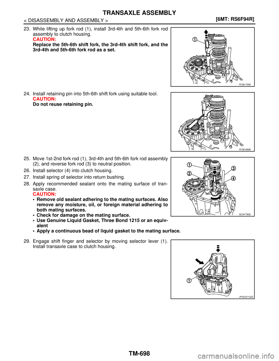
23. While lifting up fork rod (1), install 3rd-4th and 5th-6th fork rod
assembly to clutch housing.
CAUTION:
Replace the 5th-6th shift fork, the 3rd-4th shift fork, and the
3rd-4th and 5th-6th fork rod as a set.
24. Install retaining pin into 5th-6th shift fork using suitable tool.
CAUTION:
Do not reuse retaining pin.
25. Move 1st-2nd fork rod (1), 3rd-4th and 5th-6th fork rod assembly
(2), and reverse fork rod (3) to neutral position.
26. Install selector (4) into clutch housing.
27. Install spring of selector into return bushing.
28. Apply recommended sealant onto the mating surface of tran-
saxle case.
CAUTION:
Remove old sealant adhering to the mating surfaces. Also
remove any moisture, oil, or foreign material adhering to
both mating surfaces.
Check for damage on the mating surface.
Use Genuine Liquid Gasket, Three Bond 1215 or an equiv-
alent
Apply a continuous bead of liquid gasket to the mating surface.
29. Engage shift finger and selector by moving selector lever (1).
Install transaxle case to clutch housing.
PCIB1700E
PCIB1699E
SCIA7782E
JPDIC0110ZZ
Page 5645 of 5883
TRANSAXLE ASSEMBLY
TM-699
< DISASSEMBLY AND ASSEMBLY >[6MT: RS6F94R]
C
E
F
G
H
I
J
K
L
MA
B
TM
N
O
P
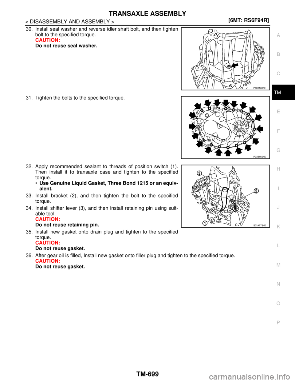
30. Install seal washer and reverse idler shaft bolt, and then tighten
bolt to the specified torque.
CAUTION:
Do not reuse seal washer.
31. Tighten the bolts to the specified torque.
32. Apply recommended sealant to threads of position switch (1).
Then install it to transaxle case and tighten to the specified
torque.
Use Genuine Liquid Gasket, Three Bond 1215 or an equiv-
alent.
33. Install bracket (2), and then tighten the bolt to the specified
torque.
34. Install shifter lever (3), and then install retaining pin using suit-
able tool.
CAUTION:
Do not reuse retaining pin.
35. Install new gasket onto drain plug and tighten to the specified
torque.
CAUTION:
Do not reuse gasket.
36. After gear oil is filled, Install new gasket onto filler plug and tighten to the specified torque.
CAUTION:
Do not reuse gasket.
PCIB1695E
PCIB1694E
SCIA7784E
Page 5664 of 5883
PRECAUTIONS
VTL-3
< PRECAUTION >[AUTOMATIC AIR CONDITIONER]
C
D
E
F
G
H
J
K
L
MA
B
VTL
N
O
P
PRECAUTION
PRECAUTIONS
Precaution for Supplemental Restraint System (SRS) "AIR BAG" and "SEAT BELT
PRE-TENSIONER"
INFOID:0000000001696273
The Supplemental Restraint System such as “AIR BAG” and “SEAT BELT PRE-TENSIONER”, used along
with a front seat belt, helps to reduce the risk or severity of injury to the driver and front passenger for certain
types of collision. Information necessary to service the system safely is included in the SR and SB section of
this Service Manual.
WARNING:
• To avoid rendering the SRS inoperative, which could increase the risk of personal injury or death in
the event of a collision which would result in air bag inflation, all maintenance must be performed by
an authorized NISSAN/INFINITI dealer.
Improper maintenance, including incorrect removal and installation of the SRS, can lead to personal
injury caused by unintentional activation of the system. For removal of Spiral Cable and Air Bag
Module, see the SR section.
Do not use electrical test equipment on any circuit related to the SRS unless instructed to in this
Service Manual. SRS wiring harnesses can be identified by yellow and/or orange harnesses or har-
ness connectors.
Precaution for Working with HFC-134a (R-134a)INFOID:0000000001696274
WARNING:
Use only specified oil for the HFC-134a (R-134a) A/C system and HFC-134a (R-134a) components. If
oil other than that specified is used, compressor malfunction is likely to occur.
The specified HFC-134a (R-134a) oil rapidly absorbs moisture from the atmosphere. The following
handling precautions must be observed:
- When removing refrigerant components from a vehicle, immediately cap (seal) the component to
minimize the entry of moisture from the atmosphere.
- When installing refrigerant components to a vehicle, do not remove the caps (unseal) until just
before connecting the components. Connect all refrigerant loop components as quickly as possible
to minimize the entry of moisture into system.
- Only use the specified oil from a sealed container. Immediately reseal containers of oil. Without
proper sealing, oil will become moisture saturated and should not be used.
- Avoid breathing A/C refrigerant and oil vapor or mist. Exposure may irritate eyes, nose and throat.
Use only approved recovery/recycling equipment to discharge HFC-134a (R-134a) refrigerant. If acci-
dental system discharge occurs, ventilate work area before resuming service. Additional health and
safety information may be obtained from refrigerant and oil manufacturers.
- Do not allow A/C oil to come in contact with styrofoam parts. Damage may result.
Page 5673 of 5883
VTL-12
< ON-VEHICLE REPAIR >[AUTOMATIC AIR CONDITIONER]
A/C UNIT ASSEMBLY
A/C UNIT ASSEMBLY
Removal and InstallationINFOID:0000000001696285
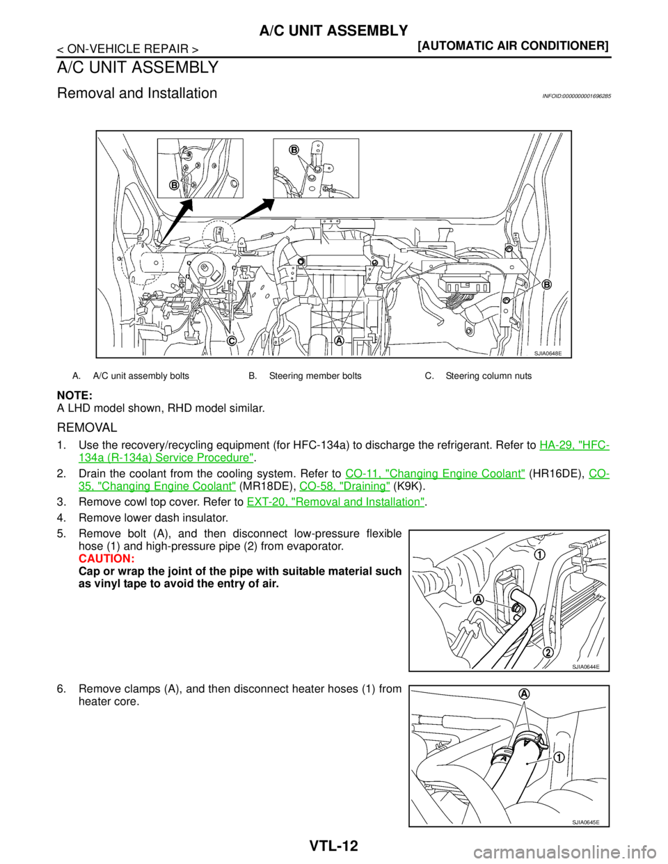
NOTE:
A LHD model shown, RHD model similar.
REMOVAL
1. Use the recovery/recycling equipment (for HFC-134a) to discharge the refrigerant. Refer to HA-29, "HFC-
134a (R-134a) Service Procedure".
2. Drain the coolant from the cooling system. Refer to CO-11, "
Changing Engine Coolant" (HR16DE), CO-
35, "Changing Engine Coolant" (MR18DE), CO-58, "Draining" (K9K).
3. Remove cowl top cover. Refer to EXT-20, "
Removal and Installation".
4. Remove lower dash insulator.
5. Remove bolt (A), and then disconnect low-pressure flexible
hose (1) and high-pressure pipe (2) from evaporator.
CAUTION:
Cap or wrap the joint of the pipe with suitable material such
as vinyl tape to avoid the entry of air.
6. Remove clamps (A), and then disconnect heater hoses (1) from
heater core.
SJIA0648E
A. A/C unit assembly bolts B. Steering member bolts C. Steering column nuts
SJIA0644E
SJIA0645E
Page 5691 of 5883
VTL-30
< PRECAUTION >[MANUAL AIR CONDITIONER]
PRECAUTIONS
PRECAUTION
PRECAUTIONS
Precaution for Supplemental Restraint System (SRS) "AIR BAG" and "SEAT BELT
PRE-TENSIONER"
INFOID:0000000001696378
The Supplemental Restraint System such as “AIR BAG” and “SEAT BELT PRE-TENSIONER”, used along
with a front seat belt, helps to reduce the risk or severity of injury to the driver and front passenger for certain
types of collision. Information necessary to service the system safely is included in the SR and SB section of
this Service Manual.
WARNING:
To avoid rendering the SRS inoperative, which could increase the risk of personal injury or death in
the event of a collision which would result in air bag inflation, all maintenance must be performed by
an authorized NISSAN/INFINITI dealer.
Improper maintenance, including incorrect removal and installation of the SRS, can lead to personal
injury caused by unintentional activation of the system. For removal of Spiral Cable and Air Bag
Module, see the SR section.
Do not use electrical test equipment on any circuit related to the SRS unless instructed to in this
Service Manual. SRS wiring harnesses can be identified by yellow and/or orange harnesses or har-
ness connectors.
Precaution for Working with HFC-134a (R-134a)INFOID:0000000001696379
WARNING:
Use only specified oil for the HFC-134a (R-134a) A/C system and HFC-134a (R-134a) components. If
oil other than that specified is used, compressor malfunction is likely to occur.
The specified HFC-134a (R-134a) oil rapidly absorbs moisture from the atmosphere. The following
handling precautions must be observed:
- When removing refrigerant components from a vehicle, immediately cap (seal) the component to
minimize the entry of moisture from the atmosphere.
- When installing refrigerant components to a vehicle, do not remove the caps (unseal) until just
before connecting the components. Connect all refrigerant loop components as quickly as possible
to minimize the entry of moisture into system.
- Only use the specified oil from a sealed container. Immediately reseal containers of oil. Without
proper sealing, oil will become moisture saturated and should not be used.
- Avoid breathing A/C refrigerant and oil vapor or mist. Exposure may irritate eyes, nose and throat.
Use only approved recovery/recycling equipment to discharge HFC-134a (R-134a) refrigerant. If acci-
dental system discharge occurs, ventilate work area before resuming service. Additional health and
safety information may be obtained from refrigerant and oil manufacturers.
- Do not allow A/C oil to come in contact with styrofoam parts. Damage may result.