NISSAN TIIDA 2008 Service Repair Manual
Manufacturer: NISSAN, Model Year: 2008, Model line: TIIDA, Model: NISSAN TIIDA 2008Pages: 2771, PDF Size: 60.61 MB
Page 311 of 2771
REPAIR FOR COMPONENT PARTS
AT-299
< SERVICE INFORMATION >
D
E
F
G
H
I
J
K
L
MA
B
AT
N
O
P
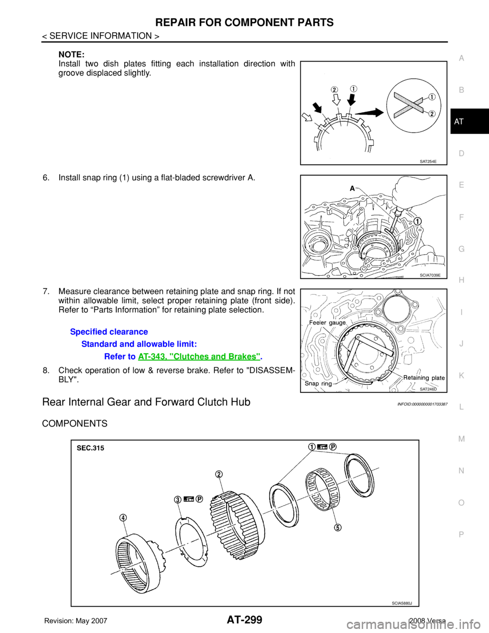
NOTE:
Install two dish plates fitting each installation direction with
groove displaced slightly.
6. Install snap ring (1) using a flat-bladed screwdriver A.
7. Measure clearance between retaining plate and snap ring. If not
within allowable limit, select proper retaining plate (front side).
Refer to “Parts Information” for retaining plate selection.
8. Check operation of low & reverse brake. Refer to "DISASSEM-
BLY".
Rear Internal Gear and Forward Clutch HubINFOID:0000000001703387
COMPONENTS
SAT254E
SCIA7039E
Specified clearance
Standard and allowable limit:
Refer to AT-343, "
Clutches and Brakes".
SAT246D
SCIA5880J
Page 312 of 2771
AT-300
< SERVICE INFORMATION >
REPAIR FOR COMPONENT PARTS
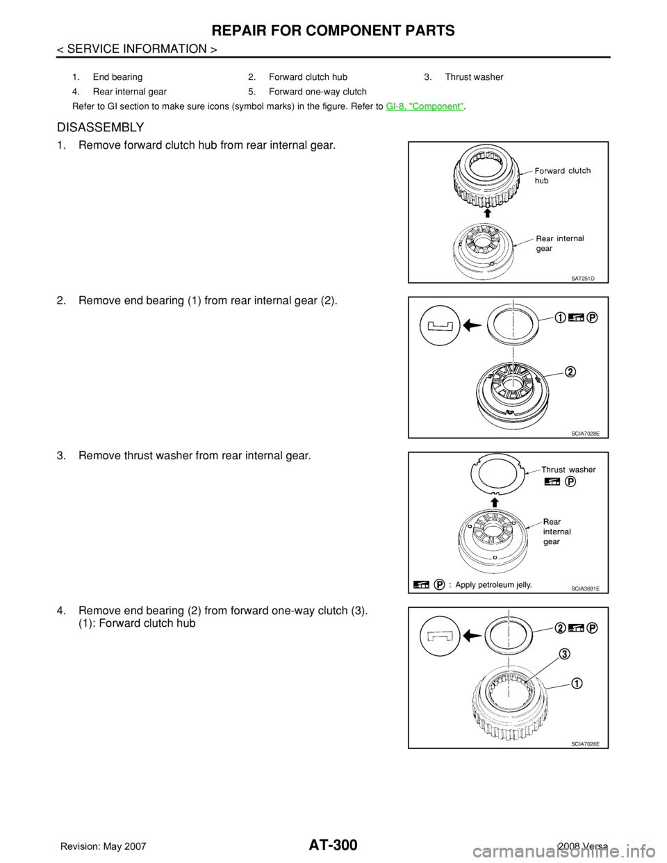
DISASSEMBLY
1. Remove forward clutch hub from rear internal gear.
2. Remove end bearing (1) from rear internal gear (2).
3. Remove thrust washer from rear internal gear.
4. Remove end bearing (2) from forward one-way clutch (3).
(1): Forward clutch hub
1. End bearing 2. Forward clutch hub 3. Thrust washer
4. Rear internal gear 5. Forward one-way clutch
Refer to GI section to make sure icons (symbol marks) in the figure. Refer to GI-8, "
Component".
SAT251D
SCIA7028E
SCIA3691E
SCIA7026E
Page 313 of 2771
REPAIR FOR COMPONENT PARTS
AT-301
< SERVICE INFORMATION >
D
E
F
G
H
I
J
K
L
MA
B
AT
N
O
P
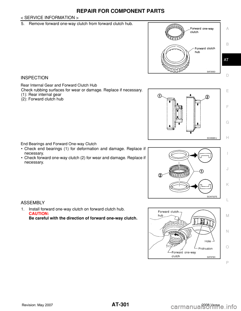
5. Remove forward one-way clutch from forward clutch hub.
INSPECTION
Rear Internal Gear and Forward Clutch Hub
Check rubbing surfaces for wear or damage. Replace if necessary.
(1): Rear internal gear
(2): Forward clutch hub
End Bearings and Forward One-way Clutch
• Check end bearings (1) for deformation and damage. Replace if
necessary.
• Check forward one-way clutch (2) for wear and damage. Replace if
necessary.
ASSEMBLY
1. Install forward one-way clutch on forward clutch hub.
CAUTION:
Be careful with the direction of forward one-way clutch.
SAT255D
SCIA5881J
SCIA7027E
SAT976H
Page 314 of 2771
AT-302
< SERVICE INFORMATION >
REPAIR FOR COMPONENT PARTS
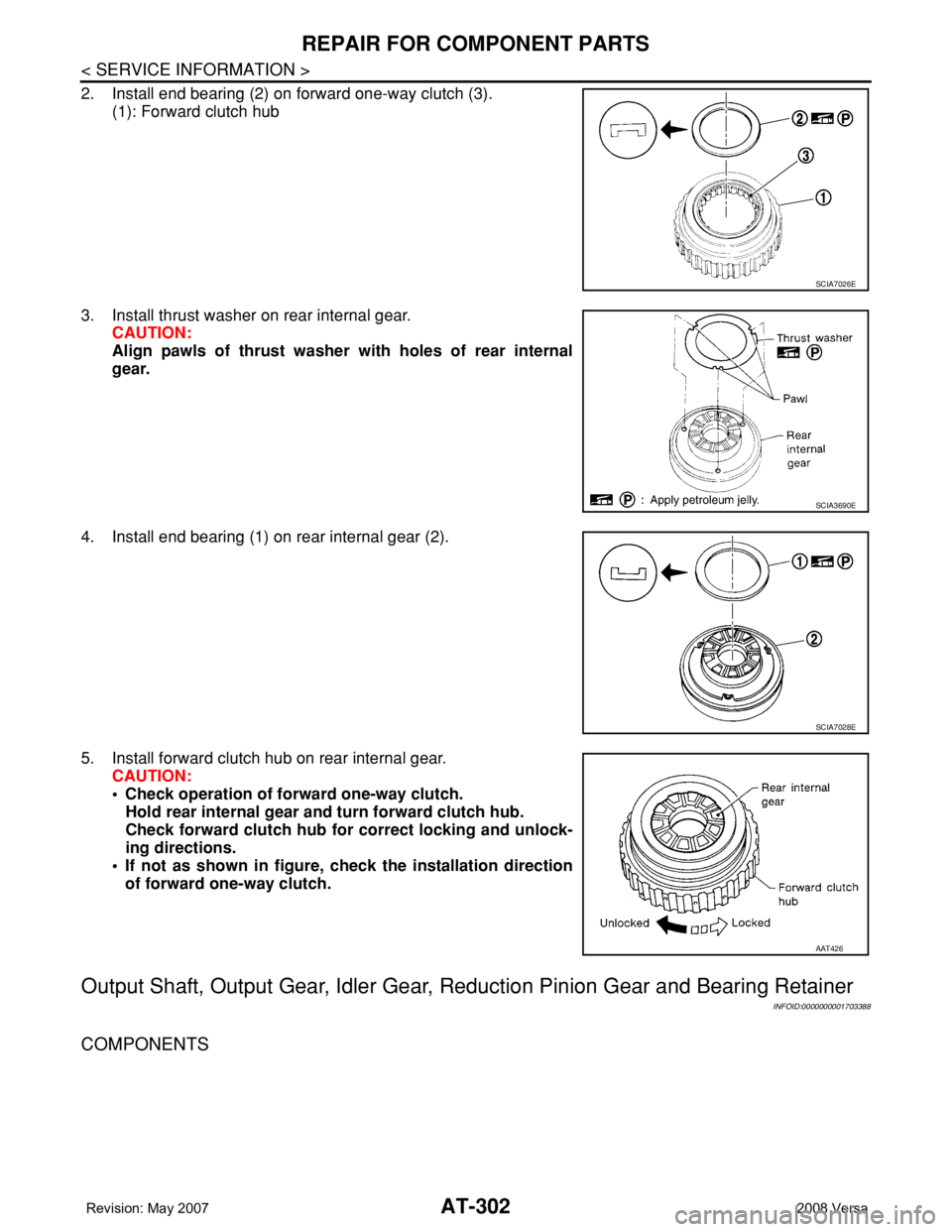
2. Install end bearing (2) on forward one-way clutch (3).
(1): Forward clutch hub
3. Install thrust washer on rear internal gear.
CAUTION:
Align pawls of thrust washer with holes of rear internal
gear.
4. Install end bearing (1) on rear internal gear (2).
5. Install forward clutch hub on rear internal gear.
CAUTION:
• Check operation of forward one-way clutch.
Hold rear internal gear and turn forward clutch hub.
Check forward clutch hub for correct locking and unlock-
ing directions.
• If not as shown in figure, check the installation direction
of forward one-way clutch.
Output Shaft, Output Gear, Idler Gear, Reduction Pinion Gear and Bearing Retainer
INFOID:0000000001703388
COMPONENTS
SCIA7026E
SCIA3690E
SCIA7028E
AAT426
Page 315 of 2771
REPAIR FOR COMPONENT PARTS
AT-303
< SERVICE INFORMATION >
D
E
F
G
H
I
J
K
L
MA
B
AT
N
O
P
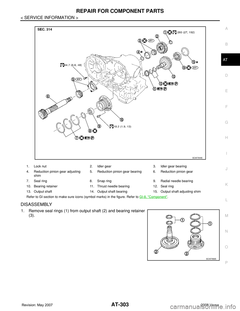
DISASSEMBLY
1. Remove seal rings (1) from output shaft (2) and bearing retainer
(3).
1. Lock nut 2. Idler gear 3. Idler gear bearing
4. Reduction pinion gear adjusting
shim5. Reduction pinion gear bearing 6. Reduction pinion gear
7. Seal ring 8. Snap ring 9. Radial needle bearing
10. Bearing retainer 11. Thrust needle bearing 12. Seal ring
13. Output shaft 14. Output shaft bearing 15. Output shaft adjusting shim
Refer to GI section to make sure icons (symbol marks) in the figure. Refer to GI-8, "
Component".
SCIA7944E
SCIA7992E
Page 316 of 2771
AT-304
< SERVICE INFORMATION >
REPAIR FOR COMPONENT PARTS
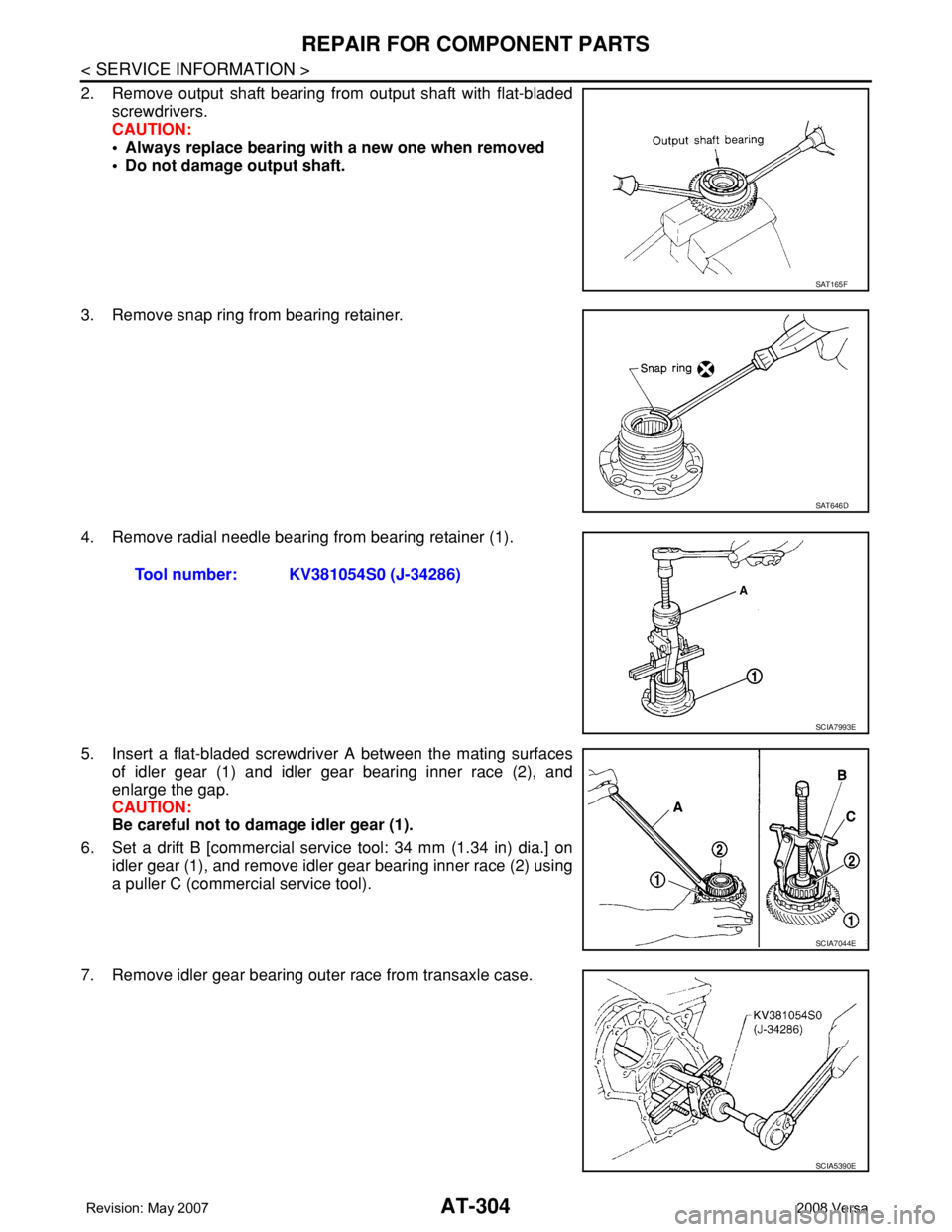
2. Remove output shaft bearing from output shaft with flat-bladed
screwdrivers.
CAUTION:
• Always replace bearing with a new one when removed
• Do not damage output shaft.
3. Remove snap ring from bearing retainer.
4. Remove radial needle bearing from bearing retainer (1).
5. Insert a flat-bladed screwdriver A between the mating surfaces
of idler gear (1) and idler gear bearing inner race (2), and
enlarge the gap.
CAUTION:
Be careful not to damage idler gear (1).
6. Set a drift B [commercial service tool: 34 mm (1.34 in) dia.] on
idler gear (1), and remove idler gear bearing inner race (2) using
a puller C (commercial service tool).
7. Remove idler gear bearing outer race from transaxle case.
SAT165F
SAT646D
Tool number: KV381054S0 (J-34286)
SCIA7993E
SCIA7044E
SCIA5390E
Page 317 of 2771
REPAIR FOR COMPONENT PARTS
AT-305
< SERVICE INFORMATION >
D
E
F
G
H
I
J
K
L
MA
B
AT
N
O
P
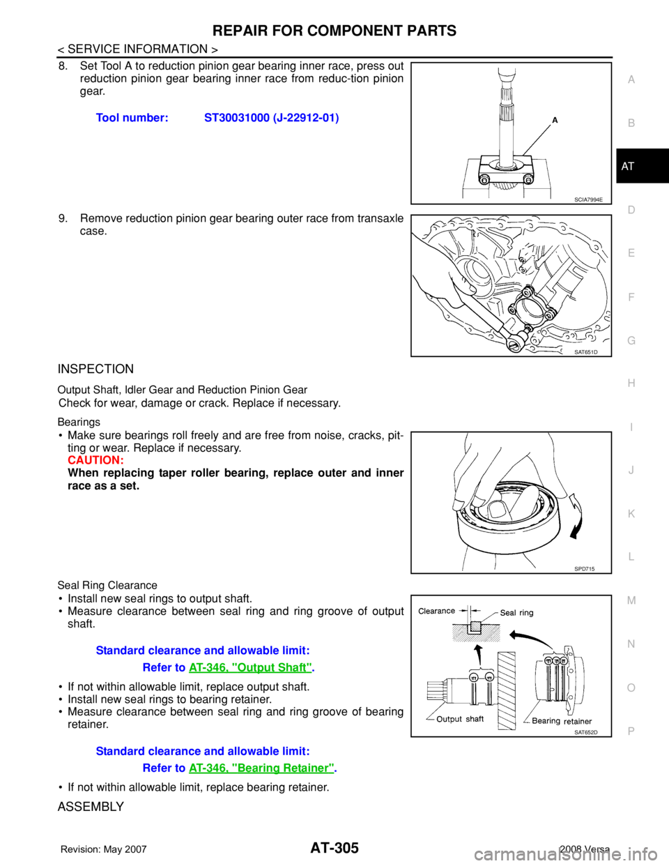
8. Set Tool A to reduction pinion gear bearing inner race, press out
reduction pinion gear bearing inner race from reduc-tion pinion
gear.
9. Remove reduction pinion gear bearing outer race from transaxle
case.
INSPECTION
Output Shaft, Idler Gear and Reduction Pinion Gear
Check for wear, damage or crack. Replace if necessary.
Bearings
• Make sure bearings roll freely and are free from noise, cracks, pit-
ting or wear. Replace if necessary.
CAUTION:
When replacing taper roller bearing, replace outer and inner
race as a set.
Seal Ring Clearance
• Install new seal rings to output shaft.
• Measure clearance between seal ring and ring groove of output
shaft.
• If not within allowable limit, replace output shaft.
• Install new seal rings to bearing retainer.
• Measure clearance between seal ring and ring groove of bearing
retainer.
• If not within allowable limit, replace bearing retainer.
ASSEMBLY
Tool number: ST30031000 (J-22912-01)
SCIA7994E
SAT651D
SPD715
Standard clearance and allowable limit:
Refer to AT-346, "
Output Shaft".
Standard clearance and allowable limit:
Refer to AT-346, "
Bearing Retainer".
SAT652D
Page 318 of 2771
AT-306
< SERVICE INFORMATION >
REPAIR FOR COMPONENT PARTS
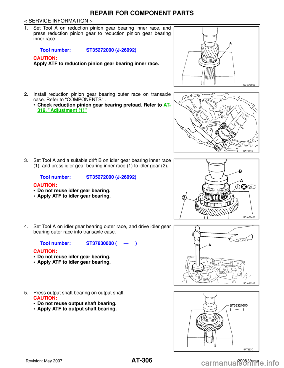
1. Set Tool A on reduction pinion gear bearing inner race, and
press reduction pinion gear to reduction pinion gear bearing
inner race.
CAUTION:
Apply ATF to reduction pinion gear bearing inner race.
2. Install reduction pinion gear bearing outer race on transaxle
case. Refer to "COMPONENTS" .
•Check reduction pinion gear bearing preload. Refer to AT-
319, "Adjustment (1)"
3. Set Tool A and a suitable drift B on idler gear bearing inner race
(1), and press idler gear bearing inner race (1) to idler gear (2).
CAUTION:
• Do not reuse idler gear bearing.
• Apply ATF to idler gear bearing.
4. Set Tool A on idler gear bearing outer race, and drive idler gear
bearing outer race into transaxle case.
CAUTION:
• Do not reuse idler gear bearing.
• Apply ATF to idler gear bearing.
5. Press output shaft bearing on output shaft.
CAUTION:
• Do not reuse output shaft bearing.
• Apply ATF to output shaft bearing.Tool number: ST35272000 (J-26092)
SCIA7995E
SAT651D
Tool number: ST35272000 (J-26092)
SCIA7046E
Tool number: ST37830000 ( — )
SCIA8031E
SAT863D
Page 319 of 2771
![NISSAN TIIDA 2008 Service Repair Manual REPAIR FOR COMPONENT PARTS
AT-307
< SERVICE INFORMATION >
D
E
F
G
H
I
J
K
L
MA
B
AT
N
O
P
6. Set drift [commercial service tool] on radial needle bearing, and
press radial needle bearing into bearing NISSAN TIIDA 2008 Service Repair Manual REPAIR FOR COMPONENT PARTS
AT-307
< SERVICE INFORMATION >
D
E
F
G
H
I
J
K
L
MA
B
AT
N
O
P
6. Set drift [commercial service tool] on radial needle bearing, and
press radial needle bearing into bearing](/img/5/57399/w960_57399-318.png)
REPAIR FOR COMPONENT PARTS
AT-307
< SERVICE INFORMATION >
D
E
F
G
H
I
J
K
L
MA
B
AT
N
O
P
6. Set drift [commercial service tool] on radial needle bearing, and
press radial needle bearing into bearing retainer.
7. Install snap ring to bearing retainer.
8. After packing ring grooves with petroleum jelly, carefully install
new seal rings (1) on output shaft (2) and bearing retainer (3).
CAUTION:
Roll paper around seal rings to prevent seal rings from
spreading.
Band Servo Piston AssemblyINFOID:0000000001703389
COMPONENTS
SAT658D
SAT659D
SCIA7996E
SCIA8011E
Page 320 of 2771
AT-308
< SERVICE INFORMATION >
REPAIR FOR COMPONENT PARTS
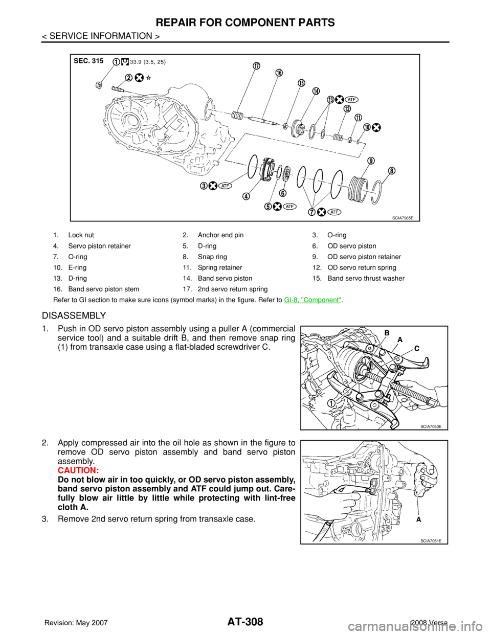
DISASSEMBLY
1. Push in OD servo piston assembly using a puller A (commercial
service tool) and a suitable drift B, and then remove snap ring
(1) from transaxle case using a flat-bladed screwdriver C.
2. Apply compressed air into the oil hole as shown in the figure to
remove OD servo piston assembly and band servo piston
assembly.
CAUTION:
Do not blow air in too quickly, or OD servo piston assembly,
band servo piston assembly and ATF could jump out. Care-
fully blow air little by little while protecting with lint-free
cloth A.
3. Remove 2nd servo return spring from transaxle case.
1. Lock nut 2. Anchor end pin 3. O-ring
4. Servo piston retainer 5. D-ring 6. OD servo piston
7. O-ring 8. Snap ring 9. OD servo piston retainer
10. E-ring 11. Spring retainer12. OD servo return spring
13. D-ring 14. Band servo piston 15. Band servo thrust washer
16. Band servo piston stem 17. 2nd servo return spring
Refer to GI section to make sure icons (symbol marks) in the figure. Refer to GI-8, "
Component".
SCIA7965E
SCIA7050E
SCIA7051E