NISSAN TIIDA 2008 Service Repair Manual
Manufacturer: NISSAN, Model Year: 2008, Model line: TIIDA, Model: NISSAN TIIDA 2008Pages: 2771, PDF Size: 60.61 MB
Page 351 of 2771
ASSEMBLY
AT-339
< SERVICE INFORMATION >
D
E
F
G
H
I
J
K
L
MA
B
AT
N
O
P
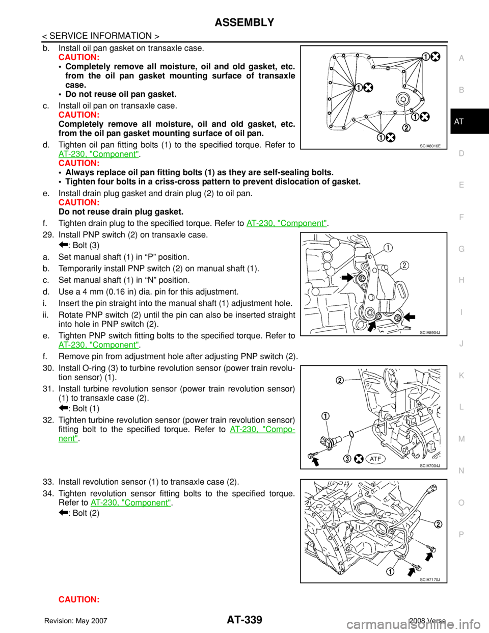
b. Install oil pan gasket on transaxle case.
CAUTION:
• Completely remove all moisture, oil and old gasket, etc.
from the oil pan gasket mounting surface of transaxle
case.
• Do not reuse oil pan gasket.
c. Install oil pan on transaxle case.
CAUTION:
Completely remove all moisture, oil and old gasket, etc.
from the oil pan gasket mounting surface of oil pan.
d. Tighten oil pan fitting bolts (1) to the specified torque. Refer to
AT-230, "
Component".
CAUTION:
• Always replace oil pan fitting bolts (1) as they are self-sealing bolts.
• Tighten four bolts in a criss-cross pattern to prevent dislocation of gasket.
e. Install drain plug gasket and drain plug (2) to oil pan.
CAUTION:
Do not reuse drain plug gasket.
f. Tighten drain plug to the specified torque. Refer to AT-230, "
Component".
29. Install PNP switch (2) on transaxle case.
: Bolt (3)
a. Set manual shaft (1) in “P” position.
b. Temporarily install PNP switch (2) on manual shaft (1).
c. Set manual shaft (1) in “N” position.
d. Use a 4 mm (0.16 in) dia. pin for this adjustment.
i. Insert the pin straight into the manual shaft (1) adjustment hole.
ii. Rotate PNP switch (2) until the pin can also be inserted straight
into hole in PNP switch (2).
e. Tighten PNP switch fitting bolts to the specified torque. Refer to
AT-230, "
Component".
f. Remove pin from adjustment hole after adjusting PNP switch (2).
30. Install O-ring (3) to turbine revolution sensor (power train revolu-
tion sensor) (1).
31. Install turbine revolution sensor (power train revolution sensor)
(1) to transaxle case (2).
: Bolt (1)
32. Tighten turbine revolution sensor (power train revolution sensor)
fitting bolt to the specified torque. Refer to AT-230, "
Compo-
nent".
33. Install revolution sensor (1) to transaxle case (2).
34. Tighten revolution sensor fitting bolts to the specified torque.
Refer to AT-230, "
Component".
: Bolt (2)
CAUTION:
SCIA8016E
SCIA5904J
SCIA7004J
SCIA7170J
Page 352 of 2771
AT-340
< SERVICE INFORMATION >
ASSEMBLY
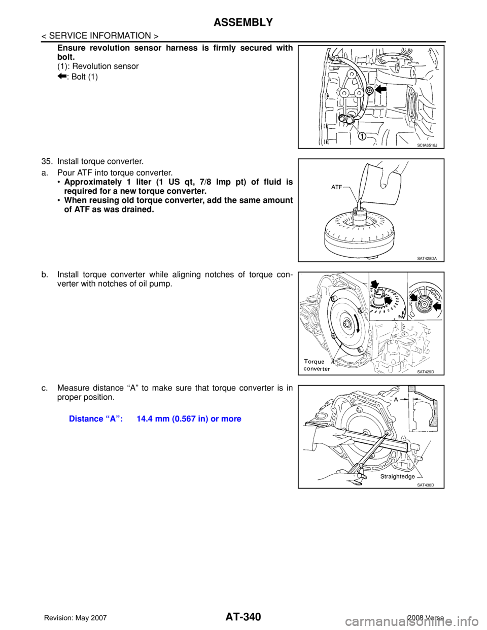
Ensure revolution sensor harness is firmly secured with
bolt.
(1): Revolution sensor
: Bolt (1)
35. Install torque converter.
a. Pour ATF into torque converter.
•Approximately 1 liter (1 US qt, 7/8 Imp pt) of fluid is
required for a new torque converter.
•When reusing old torque converter, add the same amount
of ATF as was drained.
b. Install torque converter while aligning notches of torque con-
verter with notches of oil pump.
c. Measure distance “A” to make sure that torque converter is in
proper position.
SCIA6518J
SAT428DA
SAT429D
Distance “A”: 14.4 mm (0.567 in) or more
SAT430D
Page 353 of 2771

SERVICE DATA AND SPECIFICATIONS (SDS)
AT-341
< SERVICE INFORMATION >
D
E
F
G
H
I
J
K
L
MA
B
AT
N
O
P
SERVICE DATA AND SPECIFICATIONS (SDS)
General SpecificationINFOID:0000000001703396
*: Refer to MA-10.
Vehicle Speed at Which Gear Shifting OccursINFOID:0000000001703397
• At half throttle, the accelerator opening is 4/8 of the full opening.
Vehicle Speed at When Lock-up Occurs/ReleasesINFOID:0000000001703398
Stall SpeedINFOID:0000000001703399
Line PressureINFOID:0000000001703400
Adjusting shims, Needle Bearings, Thrust Washers and Snap RingsINFOID:0000000001703401
NOTE:
EngineMR18DE
Automatic transaxle model RE4F03B
Automatic transaxle assembly Model code number 3CX0D
Transaxle gear ratio1st 2.861
2nd 1.562
3rd 1.000
4th 0.697
Reverse 2.310
Final drive 4.072
Recommended fluidGenuine NISSAN Matic D ATF (Continental U.S. and Alaska) or
Canada NISSAN Automatic Transmission Fluid*
Fluid capacity [ (US qt, Imp qt)]7.9 (8-3/8, 7)
Throttle positionVehicle speed km/h (MPH)
D1 → D2D2 → D3D3 → D4D4 → D3D3 → D2D2 → D1
Full throttle51 - 59
(32 - 37)97 - 105
(60 - 65)154 - 162
(96 - 101)150 - 158
(93 - 98)87 - 95
(54 - 59)40 - 48
(25 - 30)
Half throttle34 - 42
(21 - 26)62 - 70
(39 - 43)124 - 132
(77 - 82)69 - 77
(43 - 48)36 - 44
(22 - 27)19 - 27
(12 - 17)
Throttle position Selector lever positionVehicle speed km/h (MPH)
Lock-up ON Lock-up OFF
2.0/8“D” position 86 - 94 (53 - 58) 59 - 67 (37 - 42)
“D” position (OD OFF) 86 - 94 (53 - 58) 83 - 91 (52 - 57)
Stall revolution (rpm)2,310 - 2,770
Engine speedLine pressure kPa (kg/cm2, psi)
“D”, “2” and “1” positions “R” position
Idle speed 500 (5.1, 73) 778 (7.9, 113)
Stall speed 1,173 (12.0, 170) 1,825 (18.6, 265)
Page 354 of 2771
AT-342
< SERVICE INFORMATION >
SERVICE DATA AND SPECIFICATIONS (SDS)
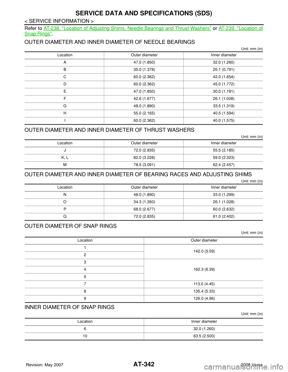
Refer to AT-238, "Location of Adjusting Shims, Needle Bearings and Thrust Washers" or AT-239, "Location of
Snap Rings".
OUTER DIAMETER AND INNER DIAMETER OF NEEDLE BEARINGS
Unit: mm (in)
OUTER DIAMETER AND INNER DIAMETER OF THRUST WASHERS
Unit: mm (in)
OUTER DIAMETER AND INNER DIAMETER OF BEARING RACES AND ADJUSTING SHIMS
Unit: mm (in)
OUTER DIAMETER OF SNAP RINGS
Unit: mm (in)
INNER DIAMETER OF SNAP RINGS
Unit: mm (in)
Location Outer diameter Inner diameter
A 47.0 (1.850) 32.0 (1.260)
B 35.0 (1.378) 20.1 (0.791)
C 60.0 (2.362) 42.0 (1.654)
D 60.0 (2.362) 45.0 (1.772)
E 47.0 (1.850) 30.0 (1.181)
F 42.6 (1.677) 26.1 (1.028)
G 48.0 (1.890) 33.5 (1.319)
H 55.0 (2.165) 40.5 (1.594)
I 60.0 (2.362) 40.0 (1.575)
Location Outer diameter Inner diameter
J 72.0 (2.835) 55.5 (2.185)
K, L 82.0 (3.228) 59.0 (2.323)
M 78.5 (3.091) 62.4 (2.457)
Location Outer diameter Inner diameter
N 48.0 (1.890) 33.0 (1.299)
O 34.3 (1.350) 26.1 (1.028)
P 68.0 (2.677) 60.0 (2.632)
Q 72.0 (2.835) 61.0 (2.402)
Location Outer diameter
1
142.0 (5.59)
2
3
162.3 (6.39) 4
5
7 113.0 (4.45)
8 135.4 (5.33)
9 126.0 (4.96)
Location Inner diameter
6 32.0 (1.260)
10 63.5 (2.500)
Page 355 of 2771
SERVICE DATA AND SPECIFICATIONS (SDS)
AT-343
< SERVICE INFORMATION >
D
E
F
G
H
I
J
K
L
MA
B
AT
N
O
P
Control ValvesINFOID:0000000001703402
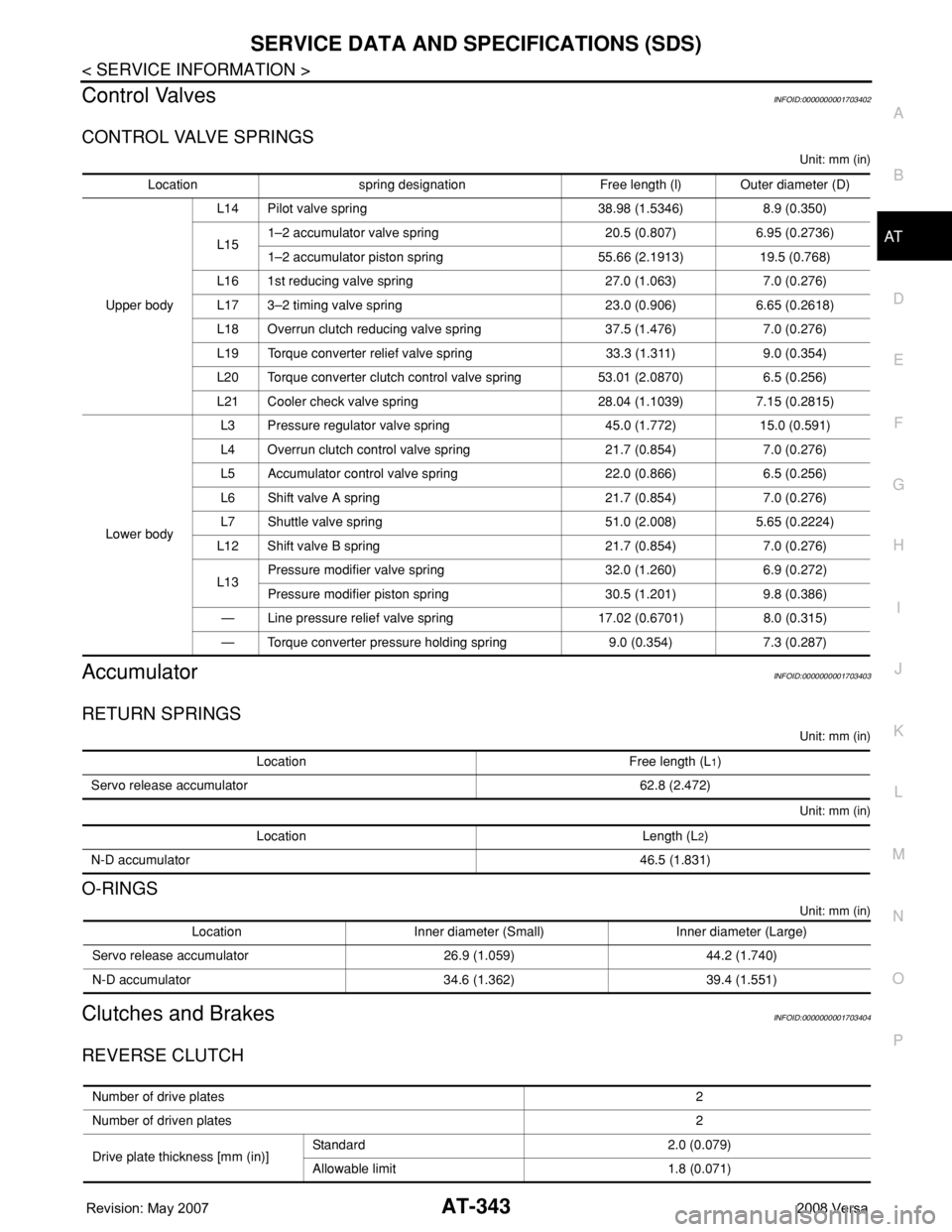
CONTROL VALVE SPRINGS
Unit: mm (in)
AccumulatorINFOID:0000000001703403
RETURN SPRINGS
Unit: mm (in)
Unit: mm (in)
O-RINGS
Unit: mm (in)
Clutches and BrakesINFOID:0000000001703404
REVERSE CLUTCH
Location spring designation Free length (l) Outer diameter (D)
Upper bodyL14 Pilot valve spring 38.98 (1.5346) 8.9 (0.350)
L151–2 accumulator valve spring 20.5 (0.807) 6.95 (0.2736)
1–2 accumulator piston spring 55.66 (2.1913) 19.5 (0.768)
L16 1st reducing valve spring 27.0 (1.063) 7.0 (0.276)
L17 3–2 timing valve spring 23.0 (0.906) 6.65 (0.2618)
L18 Overrun clutch reducing valve spring 37.5 (1.476) 7.0 (0.276)
L19 Torque converter relief valve spring 33.3 (1.311) 9.0 (0.354)
L20 Torque converter clutch control valve spring 53.01 (2.0870) 6.5 (0.256)
L21 Cooler check valve spring 28.04 (1.1039) 7.15 (0.2815)
Lower bodyL3 Pressure regulator valve spring 45.0 (1.772) 15.0 (0.591)
L4 Overrun clutch control valve spring 21.7 (0.854) 7.0 (0.276)
L5 Accumulator control valve spring 22.0 (0.866) 6.5 (0.256)
L6 Shift valve A spring 21.7 (0.854) 7.0 (0.276)
L7 Shuttle valve spring 51.0 (2.008) 5.65 (0.2224)
L12 Shift valve B spring 21.7 (0.854) 7.0 (0.276)
L13Pressure modifier valve spring 32.0 (1.260) 6.9 (0.272)
Pressure modifier piston spring 30.5 (1.201) 9.8 (0.386)
— Line pressure relief valve spring 17.02 (0.6701) 8.0 (0.315)
— Torque converter pressure holding spring 9.0 (0.354) 7.3 (0.287)
Location Free length (L1)
Servo release accumulator 62.8 (2.472)
Location Length (L2)
N-D accumulator46.5 (1.831)
Location Inner diameter (Small) Inner diameter (Large)
Servo release accumulator 26.9 (1.059) 44.2 (1.740)
N-D accumulator 34.6 (1.362) 39.4 (1.551)
Number of drive plates2
Number of driven plates2
Drive plate thickness [mm (in)]Standard 2.0 (0.079)
Allowable limit 1.8 (0.071)
Page 356 of 2771
![NISSAN TIIDA 2008 Service Repair Manual AT-344
< SERVICE INFORMATION >
SERVICE DATA AND SPECIFICATIONS (SDS)
HIGH CLUTCH
FORWARD CLUTCH
OVERRUN CLUTCH
LOW & REVERSE BRAKE
BRAKE BAND
Driven plate thickness [mm (in)] Standard 2.0 (0.079)
Clea NISSAN TIIDA 2008 Service Repair Manual AT-344
< SERVICE INFORMATION >
SERVICE DATA AND SPECIFICATIONS (SDS)
HIGH CLUTCH
FORWARD CLUTCH
OVERRUN CLUTCH
LOW & REVERSE BRAKE
BRAKE BAND
Driven plate thickness [mm (in)] Standard 2.0 (0.079)
Clea](/img/5/57399/w960_57399-355.png)
AT-344
< SERVICE INFORMATION >
SERVICE DATA AND SPECIFICATIONS (SDS)
HIGH CLUTCH
FORWARD CLUTCH
OVERRUN CLUTCH
LOW & REVERSE BRAKE
BRAKE BAND
Driven plate thickness [mm (in)] Standard 2.0 (0.079)
Clearance [mm (in)]Standard 0.5 - 0.8 (0.020 - 0.031)
Allowable limit 1.2 (0.047)
Number of drive plates4
Number of driven plates7 (1
*1 + 6*2)
Drive plate thickness [mm (in)]Standard 1.6 (0.063)
Allowable limit 1.4 (0.055)
Driven plate thickness [mm (in)] Standard
*1 *2
2.0 (0.079) 1.5 (0.059)
Clearance [mm (in)]Standard 1.4 - 1.8 (0.055 - 0.071)
Allowable limit 2.6 (0.102)
Number of drive plates5
Number of driven plates5
Drive plate thickness [mm (in)]Standard 1.8 (0.071)
Allowable limit 1.6 (0.063)
Driven plate thickness [mm (in)] Standard 2.0 (0.079)
Clearance [mm (in)]Standard 0.45 - 0.85 (0.0177 - 0.0335)
Allowable limit 1.85 (0.0728)
Number of drive plates3
Number of driven plates4
Drive plate thickness [mm (in)]Standard 1.6 (0.063)
Allowable limit 1.4 (0.055)
Driven plate thickness [mm (in)] Standard 2.0 (0.079)
Clearance [mm (in)]Standard 1.0 - 1.4 (0.039 - 0.055)
Allowable limit 2.0 (0.079)
Number of drive plates5
Number of driven plates5
Drive plate thickness [mm (in)]Standard 2.0 (0.079)
Allowable limit 1.8 (0.071)
Driven plate thickness [mm (in)] Standard 2.0 (0.079)
Clearance [mm (in)]Standard 1.4 - 1.8 (0.055 - 0.071)
Allowable limit 2.8 (0.110)
Anchor end pin tightening torque [N·m (kg-m, in-lb)] 4.9 (0.50, 43)
Number of returning revolutions for anchor end pin 2.5
Lock nut tightening torque [N·m (kg-m, ft-lb)] 33.9 (3.5, 25)
Page 357 of 2771
SERVICE DATA AND SPECIFICATIONS (SDS)
AT-345
< SERVICE INFORMATION >
D
E
F
G
H
I
J
K
L
MA
B
AT
N
O
P
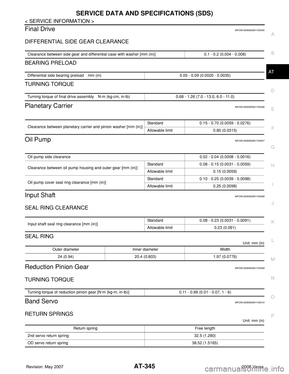
Final DriveINFOID:0000000001703405
DIFFERENTIAL SIDE GEAR CLEARANCE
BEARING PRELOAD
TURNING TORQUE
Planetary CarrierINFOID:0000000001703406
Oil PumpINFOID:0000000001703407
Input ShaftINFOID:0000000001703408
SEAL RING CLEARANCE
SEAL RING
Unit: mm (in)
Reduction Pinion GearINFOID:0000000001703409
TURNING TORQUE
Band ServoINFOID:0000000001703410
RETURN SPRINGS
Unit: mm (in)
Clearance between side gear and differential case with washer [mm (in)] 0.1 - 0.2 (0.004 - 0.008)
Differential side bearing preload mm (in) 0.05 - 0.09 (0.0020 - 0.0035)
Turning torque of final drive assembly N-m (kg-cm, in-lb) 0.68 - 1.26 (7.0 - 13.0, 6.0 - 11.0)
Clearance between planetary carrier and pinion washer [mm (in)]Standard 0.15 - 0.70 (0.0059 - 0.0276)
Allowable limit 0.80 (0.0315)
Oil pump side clearance0.02 - 0.04 (0.0008 - 0.0016)
Clearance between oil pump housing and outer gear [mm (in)]Standard 0.08 - 0.15 (0.0031 - 0.0059)
Allowable limit 0.15 (0.0059)
Oil pump cover seal ring clearance [mm (in)]Standard 0.10 - 0.25 (0.0039 - 0.0098)
Allowable limit 0.25 (0.0098)
Input shaft seal ring clearance [mm (in)]Standard 0.08 - 0.23 (0.0031 - 0.0091)
Allowable limit 0.23 (0.091)
Outer diameter Inner diameter Width
24 (0.94) 20.4 (0.803) 1.97 (0.0776)
Turning torque of reduction pinion gear [N·m (kg-m, in-lb)] 0.11 - 0.69 (0.01 - 0.07, 1 - 6)
Return spring Free length
2nd servo return spring 32.5 (1.280)
OD servo return spring 38.52 (1.5165)
Page 358 of 2771

AT-346
< SERVICE INFORMATION >
SERVICE DATA AND SPECIFICATIONS (SDS)
Output Shaft
INFOID:0000000001703411
SEAL RING CLEARANCE
SEAL RING
Unit: mm (in)
END PLAY
Bearing RetainerINFOID:0000000001703412
SEAL RING CLEARANCE
Total End PlayINFOID:0000000001703413
Reverse Clutch End PlayINFOID:0000000001703414
Removal and InstallationINFOID:0000000001703415
Shift Solenoid ValvesINFOID:0000000001703416
Solenoid ValvesINFOID:0000000001703417
Output shaft seal ring clearance [mm (in)]Standard 0.10 - 0.25 (0.0039 - 0.0098)
Allowable limit 0.25 (0.0098)
Outer diameter Inner diameter Width
29.5 (1.161) 26.2 (1.031) 1.95 (0.0768)
Output shaft end play mm (in) 0 - 0.5 (0 - 0.020)
Bearing retainer seal ring clearance [mm (in)]Standard 0.10 - 0.27 (0.0039 - 0.0106)
Allowable limit 0.27 (0.0106)
Total end play [mm (in)] 0.25 - 0.55 (0.0098 - 0.0217)
Reverse clutch end play [mm (in)] 0.65 - 1.0 (0.0256 - 0.039)
Distance between end of converter housing and torque converter [mm (in)] 14.4 (0.567)
Gear position 1 2 3 4
Shift solenoid valve A ON (Closed) OFF (Open) OFF (Open) ON (Closed)
Shift solenoid valve B ON (Closed)ON (Closed) OFF (Open) OFF (Open)
Solenoid valve designation Resistance (Approx.) Terminal
Shift solenoid valve A 20 - 30 Ω2
Shift solenoid valve B 5 - 20 Ω1
Overrun clutch solenoid valve 20 - 30 Ω3
Line pressure solenoid valve 2.5 - 5.0 Ω4
Torque converter clutch solenoid valve 5 - 20 Ω5
Page 359 of 2771
SERVICE DATA AND SPECIFICATIONS (SDS)
AT-347
< SERVICE INFORMATION >
D
E
F
G
H
I
J
K
L
MA
B
AT
N
O
P
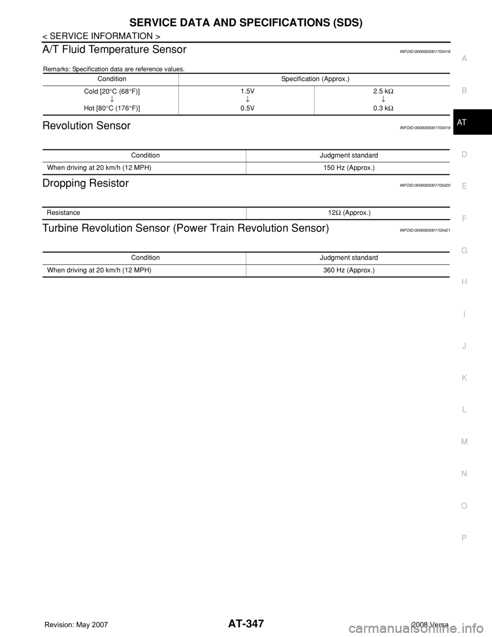
A/T Fluid Temperature SensorINFOID:0000000001703418
Remarks: Specification data are reference values.
Revolution SensorINFOID:0000000001703419
Dropping ResistorINFOID:0000000001703420
Turbine Revolution Sensor (Power Train Revolution Sensor)INFOID:0000000001703421
Condition Specification (Approx.)
Cold [20°C (68°F)]
↓
Hot [80°C (176°F)]1.5V
↓
0.5V2.5 kΩ
↓
0.3 kΩ
Condition Judgment standard
When driving at 20 km/h (12 MPH) 150 Hz (Approx.)
Resistance12Ω (Approx.)
Condition Judgment standard
When driving at 20 km/h (12 MPH) 360 Hz (Approx.)
Page 360 of 2771
AV-1
ELECTRICAL
C
D
E
F
G
H
I
J
L
M
SECTION AV
A
B
AV
N
O
P
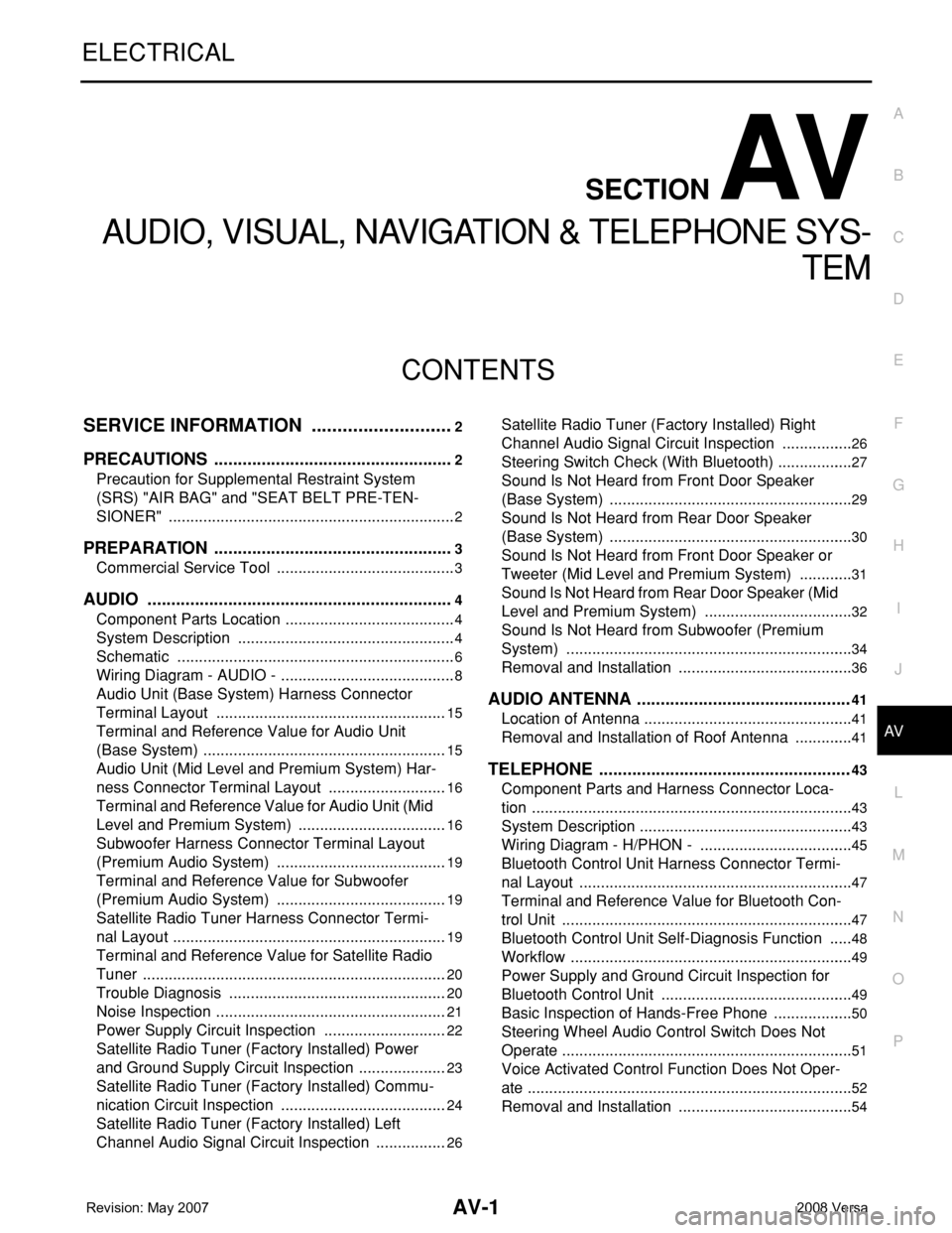
CONTENTS
AUDIO, VISUAL, NAVIGATION & TELEPHONE SYS-
TEM
SERVICE INFORMATION ............................2
PRECAUTIONS ...................................................2
Precaution for Supplemental Restraint System
(SRS) "AIR BAG" and "SEAT BELT PRE-TEN-
SIONER" ...................................................................
2
PREPARATION ...................................................3
Commercial Service Tool ..........................................3
AUDIO .................................................................4
Component Parts Location ........................................4
System Description ...................................................4
Schematic .................................................................6
Wiring Diagram - AUDIO - .........................................8
Audio Unit (Base System) Harness Connector
Terminal Layout ......................................................
15
Terminal and Reference Value for Audio Unit
(Base System) .........................................................
15
Audio Unit (Mid Level and Premium System) Har-
ness Connector Terminal Layout ............................
16
Terminal and Reference Value for Audio Unit (Mid
Level and Premium System) ...................................
16
Subwoofer Harness Connector Terminal Layout
(Premium Audio System) ........................................
19
Terminal and Reference Value for Subwoofer
(Premium Audio System) ........................................
19
Satellite Radio Tuner Harness Connector Termi-
nal Layout ................................................................
19
Terminal and Reference Value for Satellite Radio
Tuner .......................................................................
20
Trouble Diagnosis ...................................................20
Noise Inspection ......................................................21
Power Supply Circuit Inspection .............................22
Satellite Radio Tuner (Factory Installed) Power
and Ground Supply Circuit Inspection .....................
23
Satellite Radio Tuner (Factory Installed) Commu-
nication Circuit Inspection .......................................
24
Satellite Radio Tuner (Factory Installed) Left
Channel Audio Signal Circuit Inspection .................
26
Satellite Radio Tuner (Factory Installed) Right
Channel Audio Signal Circuit Inspection .................
26
Steering Switch Check (With Bluetooth) ..................27
Sound Is Not Heard from Front Door Speaker
(Base System) .........................................................
29
Sound Is Not Heard from Rear Door Speaker
(Base System) .........................................................
30
Sound Is Not Heard from Front Door Speaker or
Tweeter (Mid Level and Premium System) .............
31
Sound Is Not Heard from Rear Door Speaker (Mid
Level and Premium System) ...................................
32
Sound Is Not Heard from Subwoofer (Premium
System) ...................................................................
34
Removal and Installation .........................................36
AUDIO ANTENNA .............................................41
Location of Antenna .................................................41
Removal and Installation of Roof Antenna ..............41
TELEPHONE .....................................................43
Component Parts and Harness Connector Loca-
tion ...........................................................................
43
System Description ..................................................43
Wiring Diagram - H/PHON - ....................................45
Bluetooth Control Unit Harness Connector Termi-
nal Layout ................................................................
47
Terminal and Reference Value for Bluetooth Con-
trol Unit ....................................................................
47
Bluetooth Control Unit Self-Diagnosis Function ......48
Workflow ..................................................................49
Power Supply and Ground Circuit Inspection for
Bluetooth Control Unit .............................................
49
Basic Inspection of Hands-Free Phone ...................50
Steering Wheel Audio Control Switch Does Not
Operate ....................................................................
51
Voice Activated Control Function Does Not Oper-
ate ............................................................................
52
Removal and Installation .........................................54