NISSAN TIIDA 2008 Service Repair Manual
Manufacturer: NISSAN, Model Year: 2008, Model line: TIIDA, Model: NISSAN TIIDA 2008Pages: 2771, PDF Size: 60.61 MB
Page 371 of 2771
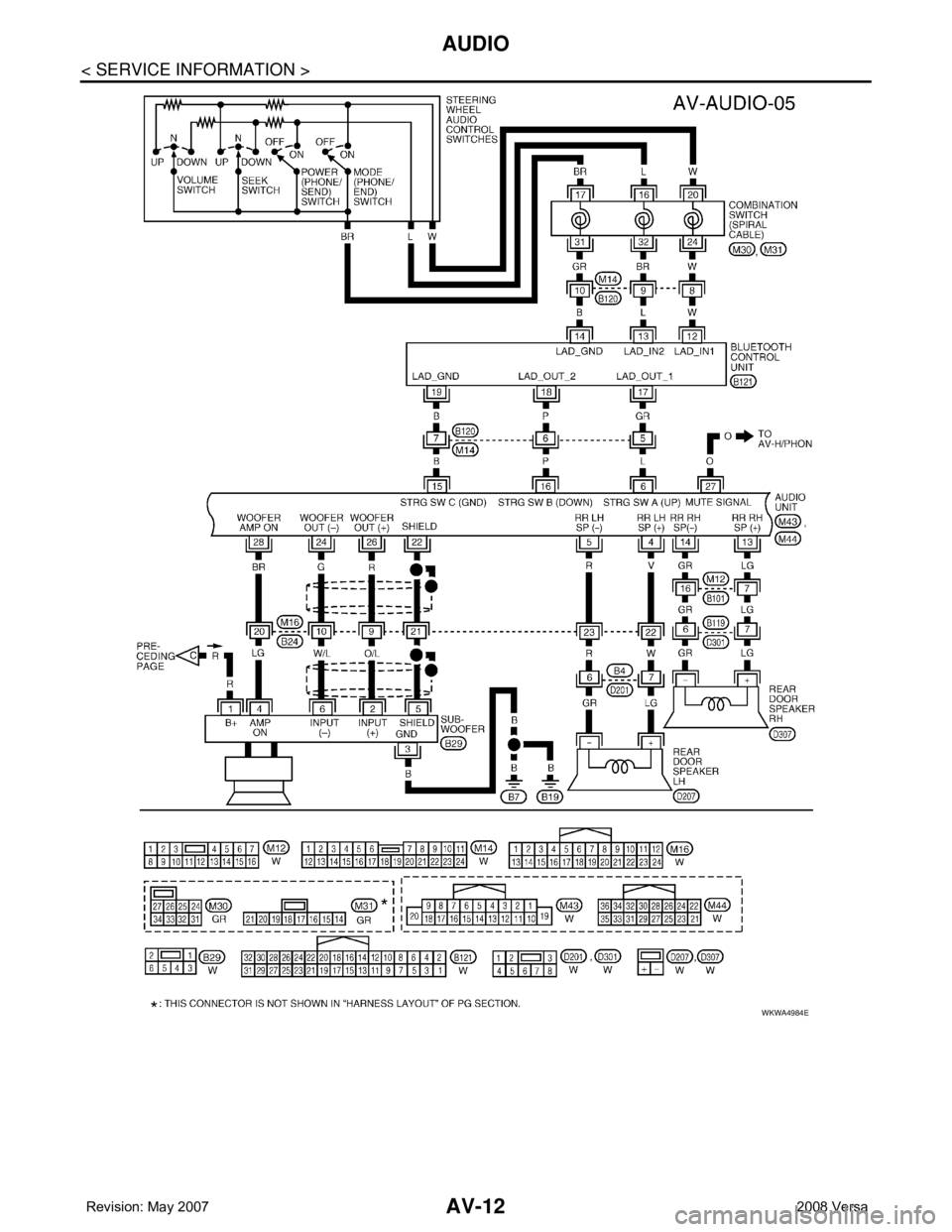
AV-12
< SERVICE INFORMATION >
AUDIO
WKWA4984E
Page 372 of 2771
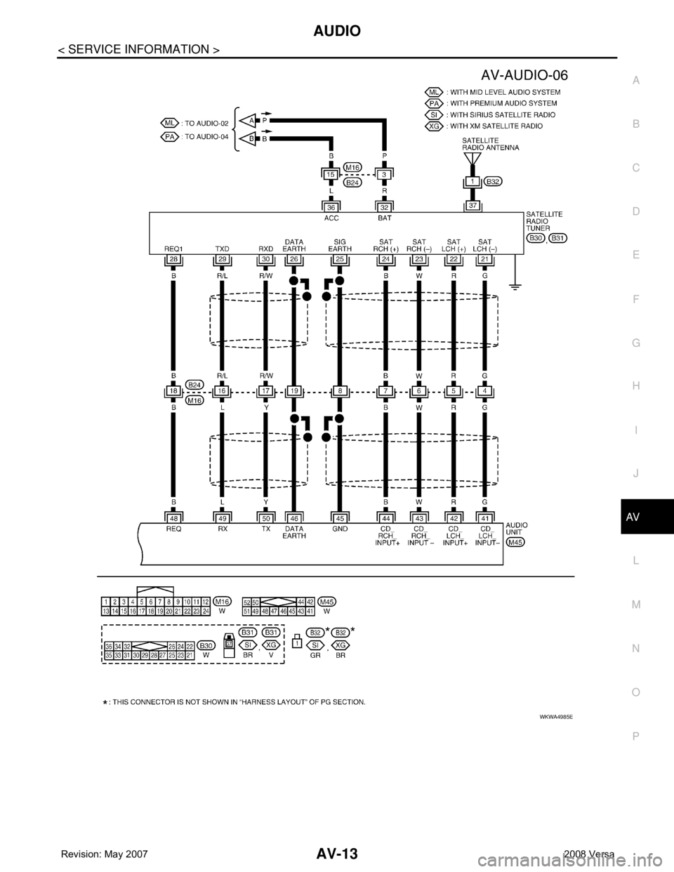
AUDIO
AV-13
< SERVICE INFORMATION >
C
D
E
F
G
H
I
J
L
MA
B
AV
N
O
P
WKWA4985E
Page 373 of 2771
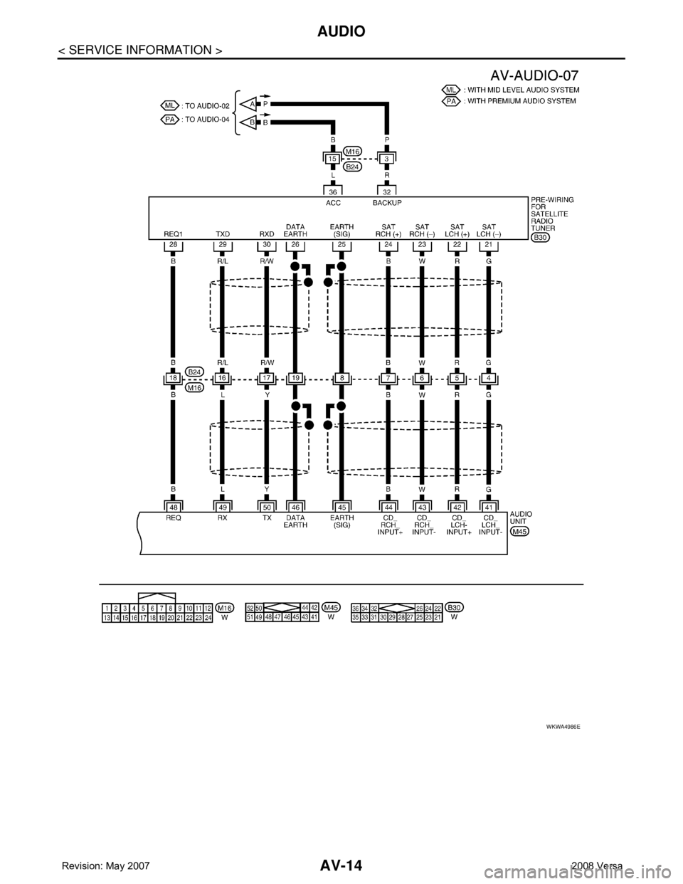
AV-14
< SERVICE INFORMATION >
AUDIO
WKWA4986E
Page 374 of 2771
AUDIO
AV-15
< SERVICE INFORMATION >
C
D
E
F
G
H
I
J
L
MA
B
AV
N
O
P
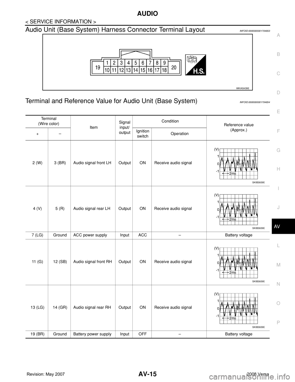
Audio Unit (Base System) Harness Connector Terminal LayoutINFOID:0000000001704653
Terminal and Reference Value for Audio Unit (Base System)INFOID:0000000001704654
WKIA5439E
Te r m i n a l
(Wire color)
ItemSignal
input/
outputCondition
Reference value
(Approx.)
+–Ignition
switchOperation
2 (W) 3 (BR) Audio signal front LH Output ON Receive audio signal
4 (V) 5 (R) Audio signal rear LH Output ON Receive audio signal
7 (LG) Ground ACC power supply Input ACC – Battery voltage
11 (G) 12 (SB) Audio signal front RH Output ON Receive audio signal
13 (LG) 14 (GR) Audio signal rear RH Output ON Receive audio signal
19 (BR) Ground Battery power supply Input OFF – Battery voltage
SKIB3609E
SKIB3609E
SKIB3609E
SKIB3609E
Page 375 of 2771
AV-16
< SERVICE INFORMATION >
AUDIO
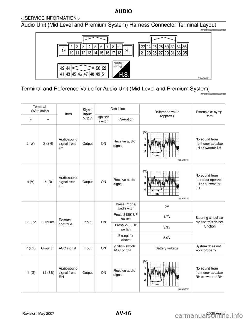
Audio Unit (Mid Level and Premium System) Harness Connector Terminal Layout
INFOID:0000000001704655
Terminal and Reference Value for Audio Unit (Mid Level and Premium System)
INFOID:0000000001704656
WKIA5440E
Te r m i n a l
(Wire color)
ItemSignal
input/
outputCondition
Reference value
(Approx.)Example of symp-
tom
+–Ignition
switchOperation
2 (W) 3 (BR)Audio sound
signal front
LHOutput ONReceive audio
signalNo sound from
front door speaker
LH or tweeter LH.
4 (V) 5 (R)Audio sound
signal rear
LHOutput ONReceive audio
signalNo sound from
rear door speaker
LH or subwoofer
LH.
6 (L)*2 GroundRemote
control AInput ONPress Phone/
End switch0V
Steering wheel au-
dio controls do not
function Press SEEK UP
switch1.7V
Press VOL UP
switch3.3V
Except for
above5.0V
7 (LG) Ground ACC signal Input ONIgnition switch
ACC or ONBattery voltageSystem does not
work properly.
11 (G) 12 (SB)Audio sound
signal front
RHOutput ONReceive audio
signalNo sound from
front door speaker
RH or tweeter RH.
SKIA0177E
SKIA0177E
SKIA0177E
Page 376 of 2771
AUDIO
AV-17
< SERVICE INFORMATION >
C
D
E
F
G
H
I
J
L
MA
B
AV
N
O
P
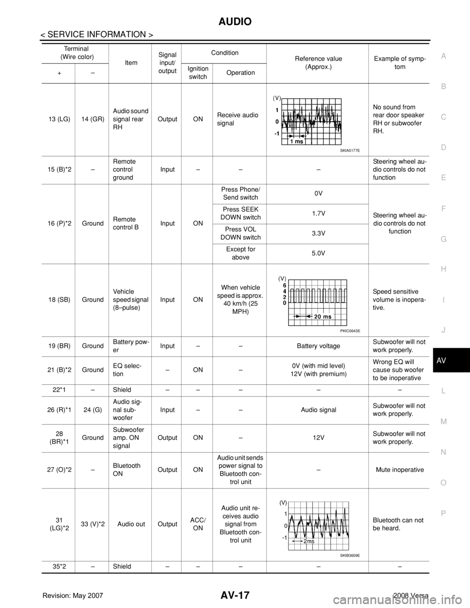
13 (LG) 14 (GR)Audio sound
signal rear
RHOutput ONReceive audio
signalNo sound from
rear door speaker
RH or subwoofer
RH.
15 (B)*2 –Remote
control
groundInput – – –Steering wheel au-
dio controls do not
function
16 (P)*2 GroundRemote
control BInput ONPress Phone/
Send switch0V
Steering wheel au-
dio controls do not
function Press SEEK
DOWN switch1.7V
Press VOL
DOWN switch3.3V
Except for
above5.0V
18 (SB) GroundVehicle
speed signal
(8–pulse)Input ONWhen vehicle
speed is approx.
40 km/h (25
MPH)Speed sensitive
volume is inopera-
tive.
19 (BR) GroundBattery pow-
erInput – – Battery voltageSubwoofer will not
work properly.
21 (B)*2 GroundEQ selec-
tion–ON –0V (with mid level)
12V (with premium)Wrong EQ will
cause sub woofer
to be inoperative
22*1 – Shield – – – – –
26 (R)*1 24 (G)Audio sig-
nal sub-
wooferInput – – Audio signalSubwoofer will not
work properly.
28
(BR)*1GroundSubwoofer
amp. ON
signalOutput ON – 12VSubwoofer will not
work properly.
27 (O)*2 –Bluetooth
ONOutput ONAudio unit sends
power signal to
Bluetooth con-
trol unit– Mute inoperative
31
(LG)*233 (V)*2 Audio out OutputACC/
ONAudio unit re-
ceives audio
signal from
Bluetooth con-
trol unitBluetooth can not
be heard.
35*2 – Shield – – – – –Te r m i n a l
(Wire color)
ItemSignal
input/
outputCondition
Reference value
(Approx.)Example of symp-
tom
+–Ignition
switchOperation
SKIA0177E
PKIC0643E
SKIB3609E
Page 377 of 2771
AV-18
< SERVICE INFORMATION >
AUDIO
*1: With premium system
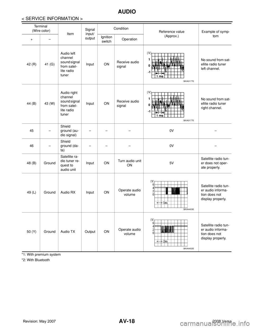
*2: With Bluetooth42 (R) 41 (G)Audio left
channel
sound signal
from satel-
lite radio
tunerInput ONReceive audio
signalNo sound from sat-
ellite radio tuner
left channel.
44 (B) 43 (W)Audio right
channel
sound signal
from satel-
lite radio
tunerInput ONReceive audio
signalNo sound from sat-
ellite radio tuner
right channel.
45 –Shield
ground (au-
dio signal)–– – 0V –
46 –Shield
ground (da-
ta)–– – 0V –
48 (B) GroundSatellite ra-
dio tuner re-
quest to
audio unitInput ONTurn audio unit
ON 5VSatellite radio tun-
er does not oper-
ate properly.
49 (L) Ground Audio RX Input ONOperate audio
volume Satellite radio tun-
er audio informa-
tion does not
display properly.
50 (Y) Ground Audio TX Output ONOperate audio
volume Satellite radio tun-
er audio informa-
tion does not
display properly. Te r m i n a l
(Wire color)
ItemSignal
input/
outputCondition
Reference value
(Approx.)Example of symp-
tom
+–Ignition
switchOperation
SKIA0177E
SKIA0177E
SKIA4403E
SKIA4402E
Page 378 of 2771
AUDIO
AV-19
< SERVICE INFORMATION >
C
D
E
F
G
H
I
J
L
MA
B
AV
N
O
P
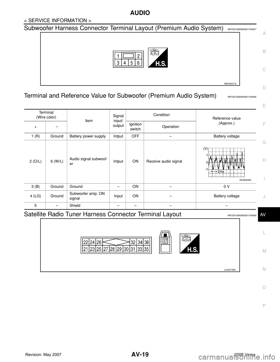
Subwoofer Harness Connector Terminal Layout (Premium Audio System)INFOID:0000000001704657
Terminal and Reference Value for Subwoofer (Premium Audio System)INFOID:0000000001704658
Satellite Radio Tuner Harness Connector Terminal LayoutINFOID:0000000001704659
WKIA5441E
Te r m i n a l
(Wire color)
ItemSignal
input/
outputCondition
Reference value
(Approx.)
+–Ignition
switchOperation
1 (R) Ground Battery power supply Intput OFF – Battery voltage
2 (O/L) 6 (W/L)Audio signal subwoof-
erIntput ON Receive audio signal
3 (B) Ground Ground – ON – 0 V
4 (LG) GroundSubwoofer amp. ON
signalInput ON – Battery voltage
5–Shield –– – –
SKIB3609E
LKIA0735E
Page 379 of 2771
AV-20
< SERVICE INFORMATION >
AUDIO
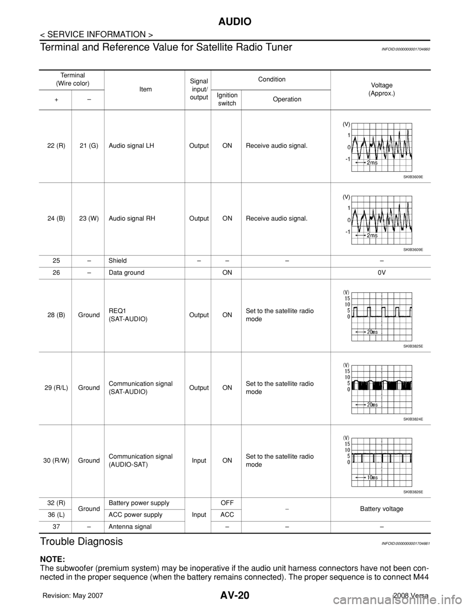
Terminal and Reference Value for Satellite Radio Tuner
INFOID:0000000001704660
Trouble DiagnosisINFOID:0000000001704661
NOTE:
The subwoofer (premium system) may be inoperative if the audio unit harness connectors have not been con-
nected in the proper sequence (when the battery remains connected). The proper sequence is to connect M44
Te r m i n a l
(Wire color)
ItemSignal
input/
outputCondition
Vol tag e
(Approx.)
+–Ignition
switchOperation
22 (R) 21 (G) Audio signal LH Output ON Receive audio signal.
24 (B) 23 (W) Audio signal RH Output ON Receive audio signal.
25 – Shield – – – –
26 – Data ground ON 0V
28 (B) GroundREQ1
(SAT-AUDIO)Output ONSet to the satellite radio
mode
29 (R/L) GroundCommunication signal
(SAT-AUDIO)Output ONSet to the satellite radio
mode
30 (R/W) GroundCommunication signal
(AUDIO-SAT)Input ONSet to the satellite radio
mode
32 (R)
GroundBattery power supply
InputOFF
−Battery voltage
36 (L) ACC power supply ACC
37 – Antenna signal – – –
SKIB3609E
SKIB3609E
SKIB3825E
SKIB3824E
SKIB3826E
Page 380 of 2771
AUDIO
AV-21
< SERVICE INFORMATION >
C
D
E
F
G
H
I
J
L
MA
B
AV
N
O
P
and M45 first followed by M43 last. If the subwoofer is inoperative, be sure to check this condition. Refer to AV-
34, "Sound Is Not Heard from Subwoofer (Premium System)" .
• The majority of the audio malfunctions are the result of outside causes (damaged CD, electromagnetic inter-
ference, etc.). Check the symptoms below to diagnose the malfunction.
• The vehicle itself can be a source of noise if noise prevention parts or electrical equipment is malfunctioning.
Check if noise is caused and/or changed by engine speed, ignition switch turned to each position, and oper-
ation of each piece of electrical equipment, and then determine the cause.
NOTE:
Noise resulting from variations in field strength, such as fading noise and multi-path noise, or external noise
from trains and other sources. It is not a malfunction.
• Fading noise: This noise occurs because of variations in the field strength in a narrow range due to moun-
tains or buildings blocking the signal.
• Multi-path noise: This noise results from the waves sent directly from the broadcast station arriving at the
antenna at a different time from the waves that reflect off of mountains or buildings.
Noise InspectionINFOID:0000000001704662
The vehicle itself can be a source of noise if noise prevention parts or electrical equipment is malfunctioning.
Check if noise is caused and/or changed by engine speed, ignition switch turned to each position, and opera-
tion of each piece of electrical equipment, and determine the cause.
NOTE:
The source of the noise can be found easily by listening to the noise while removing the fuses of electrical
components, one by one.
TYPE OF NOISE AND POSSIBLE CAUSE
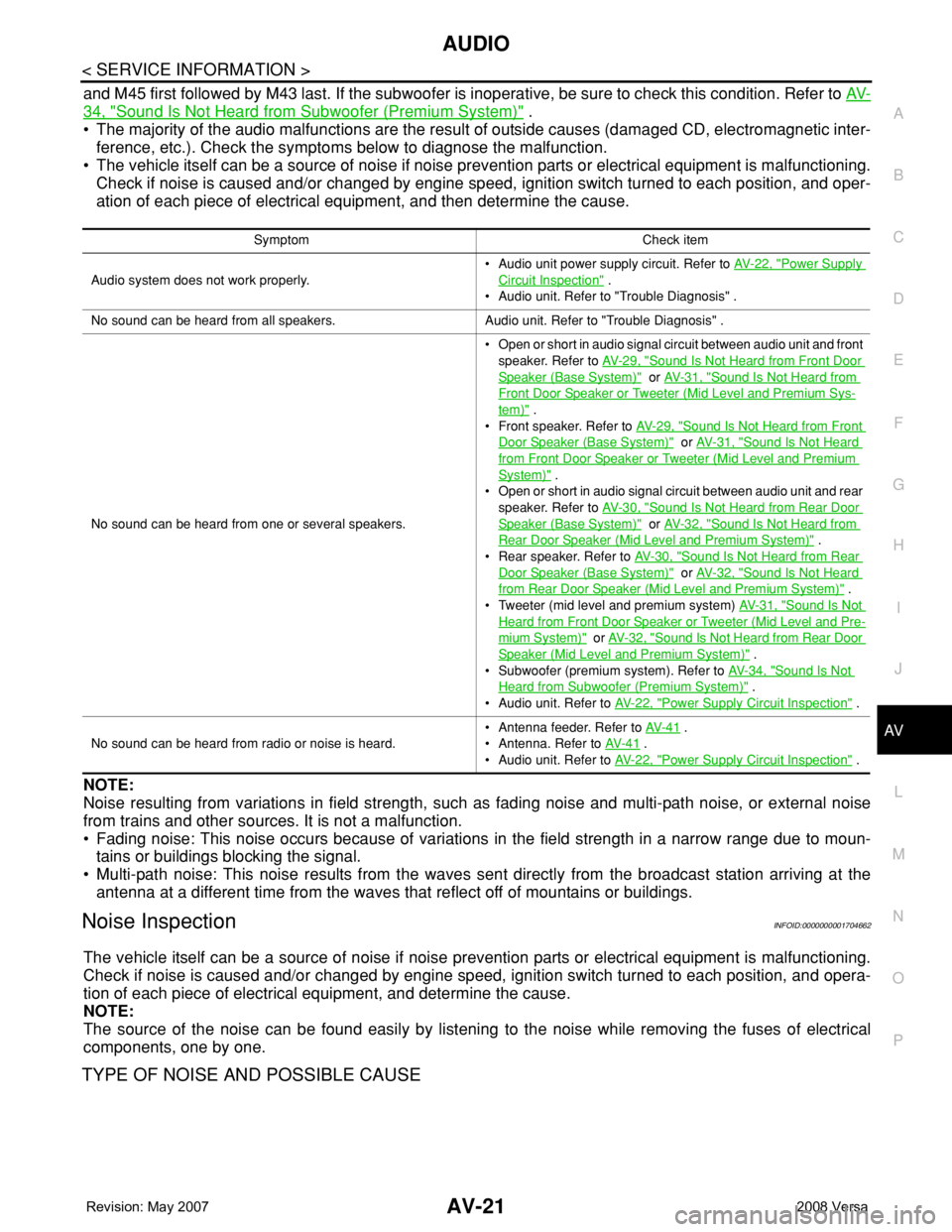
Symptom Check item
Audio system does not work properly.• Audio unit power supply circuit. Refer to AV- 2 2 , "
Power Supply
Circuit Inspection" .
• Audio unit. Refer to "Trouble Diagnosis" .
No sound can be heard from all speakers. Audio unit. Refer to "Trouble Diagnosis" .
No sound can be heard from one or several speakers.• Open or short in audio signal circuit between audio unit and front
speaker. Refer to AV- 2 9 , "
Sound Is Not Heard from Front Door
Speaker (Base System)" or AV- 3 1 , "Sound Is Not Heard from
Front Door Speaker or Tweeter (Mid Level and Premium Sys-
tem)" .
• Front speaker. Refer to AV- 2 9 , "
Sound Is Not Heard from Front
Door Speaker (Base System)" or AV- 3 1 , "Sound Is Not Heard
from Front Door Speaker or Tweeter (Mid Level and Premium
System)" .
• Open or short in audio signal circuit between audio unit and rear
speaker. Refer to AV- 3 0 , "
Sound Is Not Heard from Rear Door
Speaker (Base System)" or AV- 3 2 , "Sound Is Not Heard from
Rear Door Speaker (Mid Level and Premium System)" .
• Rear speaker. Refer to AV- 3 0 , "
Sound Is Not Heard from Rear
Door Speaker (Base System)" or AV- 3 2 , "Sound Is Not Heard
from Rear Door Speaker (Mid Level and Premium System)" .
• Tweeter (mid level and premium system) AV- 3 1 , "
Sound Is Not
Heard from Front Door Speaker or Tweeter (Mid Level and Pre-
mium System)" or AV- 3 2 , "Sound Is Not Heard from Rear Door
Speaker (Mid Level and Premium System)" .
• Subwoofer (premium system). Refer to AV- 3 4 , "
Sound Is Not
Heard from Subwoofer (Premium System)" .
• Audio unit. Refer to AV- 2 2 , "
Power Supply Circuit Inspection" .
No sound can be heard from radio or noise is heard.• Antenna feeder. Refer to AV- 4 1
.
• Antenna. Refer to AV- 4 1
.
• Audio unit. Refer to AV- 2 2 , "
Power Supply Circuit Inspection" .