NISSAN TIIDA 2010 Service Repair Manual
Manufacturer: NISSAN, Model Year: 2010, Model line: TIIDA, Model: NISSAN TIIDA 2010Pages: 3745, PDF Size: 73.67 MB
Page 3311 of 3745
MTC-32
< SERVICE INFORMATION >
TROUBLE DIAGNOSIS
1. Turn blower control dial clockwise to "1" position. Blower should operate on low speed.
2. Turn blower control dial clockwise to "2" position, and continue checking blower speed until all speeds are
checked.
3. Leave blower on Maximum speed.
If NG, go to trouble diagnosis procedure for MTC-34, "
Front Blower Motor Circuit".
If OK, continue the check.
CHECKING DISCHARGE AIR
1. Turn mode door control dial to each position.
2. Confirm that discharge air comes out according to the air distribution table. Refer to MTC-20, "
Discharge
Air Flow".
If NG, go to trouble diagnosis procedure for MTC-32, "
Mode Door".
If OK, continue the check.
CHECKING RECIRCULATION
1. Set intake door lever to REC position.
2. Operate intake door lever to FRE position.
3. Listen for intake door position change (you should hear blower sound change slightly).
If NG, go to trouble diagnosis procedure for MTC-34, "
Intake Door".
If OK, continue the check.
CHECKING TEMPERATURE DECREASE
1. Turn temperature control dial counterclockwise to full cold position.
2. Check for cold air at discharge air outlets.
If NG, go to trouble diagnosis procedure for MTC-46, "
Insufficient Cooling".
If OK, continue the check.
CHECKING TEMPERATURE INCREASE
1. Turn temperature control dial clockwise to full hot position.
2. Check for hot air at discharge air outlets.
If NG, go to trouble diagnosis procedure for MTC-53, "
Insufficient Heating".
If OK, continue the check.
CHECKING A/C SWITCH (IF EQUIPPED)
1. Turn fan control dial to the desired (1 to 4 speed) position.
2. Press A/C switch.
3. A/C switch indicator will turn ON.
• Confirm that the compressor clutch engages (sound or visual inspection).
If NG, go to trouble diagnosis procedure for MTC-38, "
Magnet Clutch Circuit (If Equipped)".
If OK, continue the check.
CHECKING DEFROST A/C SWITCH (IF EQUIPPED)
1. Turn fan control dial to the desired (1 to 4 speed) position.
2. Turn mode dial to ( ) DEF.
3. Confirm that the compressor clutch engages (sound or visual inspection) and the A/C switch indicator illu- minates.
If NG, go to trouble diagnosis procedure for MTC-38, "
Magnet Clutch Circuit (If Equipped)".
If all operational checks are OK (symptom cannot be duplicated), go to MTC-23, "
How to Perform Trouble
Diagnosis for Quick and Accurate Repair" and perform tests as outlined. If symptom appears, refer to MTC-23,
"How to Perform Trouble Diagnosis for Quick and Accurate Repair" and perform applicable trouble diagnosis
procedures.
Mode DoorINFOID:0000000005396498
SYMPTOM: Air outlet does not change.
INSPECTION FLOW
Revision: January 20102010 Versa
Page 3312 of 3745
TROUBLE DIAGNOSISMTC-33
< SERVICE INFORMATION >
C
DE
F
G H
I
K L
M A
B
MTC
N
O P
1.CONFIRM SYMPTOM BY PERFORMING O PERATIONAL CHECK - DISCHARGE AIR
1. Rotate the mode door control dial to each position.
2. Confirm that discharge air comes out accord ing to the air distribution table. Refer to MTC-20, "
Discharge
Air Flow".
NOTE:
Confirm that the compressor clutch (with A/C) is engaged (visual inspection) when DEF ( ) or D/F ( )
is selected.
Can a symptom be duplicated?
YES >> GO TO 3.
NO >> GO TO 2.
2.PERFORM COMPLETE OPERATIONAL CHECK
Perform a complete operational check and check for any symptoms. Refer to MTC-31, "
Operational Check".
Can a symptom be duplicated?
YES >> Refer to MTC-23, "How to Perform Trouble Diagnosis for Quick and Accurate Repair".
NO >> System OK.
3.CHECK FOR SERVICE BULLETINS
Check for any service bulletins.
>> GO TO 4.
4.CHECK MODE DOOR CONTROL CABLE
Check and verify mode door mechanism for smooth operation in each mode.
OK or NG
OK >> If the symptom still exists, perform a comple te operational check and check for other symptoms.
Refer to MTC-31, "
Operational Check". If other symptoms exist, refer to MTC-23, "How to Perform
Trouble Diagnosis for Quick and Accurate Repair" .
NG >> Repair or adjust mode door control cable. Refer to MTC-66, "
Mode Door Cable Adjustment".
Air Mix DoorINFOID:0000000005396499
SYMPTOM: Air mix door does not change.
INSPECTION FLOW
1.CONFIRM SYMPTOM BY PERFORMING OPERATIONAL CHECK - TEMPERATURE INCREASE
1. Turn the temperature control dial clockwise until maximum heat.
2. Check for hot air at discharge air outlets.
>> GO TO 2.
2.CONFIRM SYMPTOM BY PERFORMING OPERAT IONAL CHECK - TEMPERATURE DECREASE
1. Turn the temperature control dial counterclockwise until maximum cold.
2. Check for cold air at discharge air outlets.
Can a symptom be duplicated?
YES >> GO TO 4.
NO >> GO TO 3.
3.PERFORM COMPLETE OPERATIONAL CHECK
Perform a complete operational check and check for any symptoms. Refer to MTC-31, "
Operational Check".
Can a symptom be duplicated?
YES >> Refer to MTC-23, "How to Perform Trouble Diagnosis for Quick and Accurate Repair".
NO >> System OK.
4.CHECK FOR SERVICE BULLETINS
Check for any service bulletins.
Revision: January 20102010 Versa
Page 3313 of 3745
MTC-34
< SERVICE INFORMATION >
TROUBLE DIAGNOSIS
>> GO TO 5.
5.CHECK AIR MIX DOOR CONTROL LINKAGE
Check and verify air mix door mechanism for smooth operation.
OK or NG
OK >> If the symptom still exists, perform a complete operational check. Refer to MTC-31, "Operational
Check" If other symptoms exist, refer to MTC-23, "How to Perform Trouble Diagnosis for Quick
and Accurate Repair".
NG >> Repair or adjust air mix door control linkage. Refer to MTC-65, "
Air Mix Door Cable Adjustment".
Intake DoorINFOID:0000000005396500
SYMPTOM:
• Intake door does not change.
INSPECTION FLOW
1.CONFIRM SYMPTOM BY PERFORMING OPERATIONAL CHECK - REC ( )
1. Slide the intake door lever to the REC ( ) position.
2. Turn the blower motor to maximum speed.
3. Slide the intake door lever to the FRE position.
4. Listen for intake door position change (you should hear blower sound change slightly).
Can a symptom be duplicated?
YES >> GO TO 3.
NO >> GO TO 2.
2.PERFORM COMPLETE OPERATIONAL CHECK
Perform a complete operational check and check for any symptoms. Refer to MTC-31, "
Operational Check" .
Can a symptom be duplicated?
YES >> Refer to MTC-23, "How to Perform Trouble Diagnosis for Quick and Accurate Repair" .
NO >> System OK.
3.CHECK FOR SERVICE BULLETINS
Check for any service bulletins.
>> GO TO 4.
4.CHECK INTAKE DOOR CONTROL LINKAGE
Check intake door control linkage mechanism for smooth operation.
OK or NG
OK >> If the symptom still exists, perform a complete operational check. Refer to MTC-31, "Operational
Check" . If other symptoms exist, refer to MTC-23, "How to Perform Trouble Diagnosis for Quick
and Accurate Repair" .
NG >> Repair or adjust control linkage. Refer to MTC-64, "
Intake Door Cable Adjustment" .
Front Blower Motor CircuitINFOID:0000000005396501
SYMPTOM: Front blower motor operation is malfunctioning.
INSPECTION FLOW
1.CONFIRM SYMPTOM BY PERFORMING OPERATIONAL CHECK - FRONT BLOWER
1. Turn blower control dial to "1" position. Blower should operate on low speed.
2. Turn the blower control dial to "2" position, and continue checking blower speed until all speeds are
checked.
Can the symptom be duplicated?
YES >> GO TO 3.
Revision: January 20102010 Versa
Page 3314 of 3745
TROUBLE DIAGNOSISMTC-35
< SERVICE INFORMATION >
C
DE
F
G H
I
K L
M A
B
MTC
N
O P
NO >> GO TO 2.
2.PERFORM COMPLETE OPERATIONAL CHECK
Perform a complete operational check and check for any symptoms. Refer to MTC-31, "
Operational Check".
Can a symptom be duplicated?
YES >> Refer to MTC-23, "How to Perform Trouble Diagnosis for Quick and Accurate Repair".
NO >> System OK.
3.CHECK FOR SERVICE BULLETINS
Check for any service bulletins.
>> GO TO 4.
4.CHECK FRONT BLOWER MOTOR CIRCUIT
Check front blower motor circuit. Refer to "D IAGNOSTIC PROCEDURE FOR FRONT BLOWER MOTOR" .
OK or NG
OK >> If the symptom still exists, perform a complete operational check. Refer to MTC-31, "Operational
Check". If other symptoms exist, refer to MTC-23, "How to Perform Trouble Diagnosis for Quick
and Accurate Repair".
NG >> Repair as necessary.
DIAGNOSTIC PROCEDURE FOR FRONT BLOWER MOTOR
SYMPTOM: Blower motor operation is malfunctioning.
1.CHECK FRONT BLOWER MOTOR OPERATION
1. Turn ignition switch ON.
2. Check front blower motor operation at each fan speed.
OK or NG
OK >> Inspection End.
NG >> • Front blower motor does not operate at any speed, GO TO 2. • Front blower motor does not operate at one or more of the four speeds, GO TO 10.
2.CHECK POWER SUPPLY FOR FRONT BLOWER MOTOR
1. Turn ignition switch OFF.
2. Disconnect front blower motor connector.
3. Turn ignition switch ON.
4. Check voltage between front blower motor harness connector M62 terminal 1 and ground.
OK or NG
OK >> GO TO 6.
WJIA2259E
Te r m i n a l s Vol tag e
(Approx.)
(+)
(− )
Connector Terminal Ground
Front blower
motor: M62 1
Battery voltage
WJIA2228E
Revision: January 20102010 Versa
Page 3315 of 3745
![NISSAN TIIDA 2010 Service Repair Manual MTC-36
< SERVICE INFORMATION >
TROUBLE DIAGNOSIS
NG >> Check power supply circuit and 15A fuses [Nos. 15 and 17, located in the fuse block (J/B)].Refer to PG-4, "
Schematic".
• If fuses are OK, rein NISSAN TIIDA 2010 Service Repair Manual MTC-36
< SERVICE INFORMATION >
TROUBLE DIAGNOSIS
NG >> Check power supply circuit and 15A fuses [Nos. 15 and 17, located in the fuse block (J/B)].Refer to PG-4, "
Schematic".
• If fuses are OK, rein](/img/5/57397/w960_57397-3314.png)
MTC-36
< SERVICE INFORMATION >
TROUBLE DIAGNOSIS
NG >> Check power supply circuit and 15A fuses [Nos. 15 and 17, located in the fuse block (J/B)].Refer to PG-4, "
Schematic".
• If fuses are OK, reinstall fuses and GO TO 3.
• If fuses are NG, replace fuse and check harness for short circuit. Repair or replace if necessary.
3.CHECK BLOWER MOTOR RELAY POWER SUPPLY CIRCUITS
1. Turn ignition switch OFF.
2. Disconnect blower motor relay connector.
3. Turn ignition switch ON.
4. Check voltage between blower motor relay harness connector J- 1 terminal 1, 5 and ground.
OK or NG
OK >> GO TO 4.
NG >> Repair harness or connector.
4.CHECK BLOWER MOTOR RELAY (S WITCH SIDE) CIRCUIT FOR OPEN
1. Turn ignition switch OFF.
2. Check continuity between blower motor relay harness connector J-1 (A) terminal 3 and front blower motor harness connector
M62 (B) terminal 1.
OK or NG
OK >> GO TO 5.
NG >> Repair harness or connector.
5.CHECK BLOWER MOTOR RELAY GROUND CIRCUIT
Check continuity between blower motor relay harness connector J-1
terminal 2 and ground.
OK or NG
OK >> Replace blower motor relay.
NG >> Repair harness or connector.
6.CHECK FRONT BLOWER MOTOR
Check continuity between front blower motor terminals 1 and 2.
NOTE:
Ensure that there are no foreign particles inside the A/C unit assem-
bly for a smooth rotation of the front blower motor.
OK or NG
OK >> GO TO 7.
NG >> Replace front blower motor. Refer to MTC-63, "
Removal
and Installation".
7.CHECK CIRCUIT CONTINUITY BETWEEN FRONT BLOWER MOTOR AND FRONT AIR CONTROL
1 - Ground Battery voltage should exist.
5 - Ground Battery voltage should exist.
WJIA1783E
Continuity should exist.
WJIA2263E
Continuity should exist.
WJIA2264E
1 - 2
: Continuity should exist.
WJIA2230E
Revision: January 20102010 Versa
Page 3316 of 3745
TROUBLE DIAGNOSISMTC-37
< SERVICE INFORMATION >
C
DE
F
G H
I
K L
M A
B
MTC
N
O P
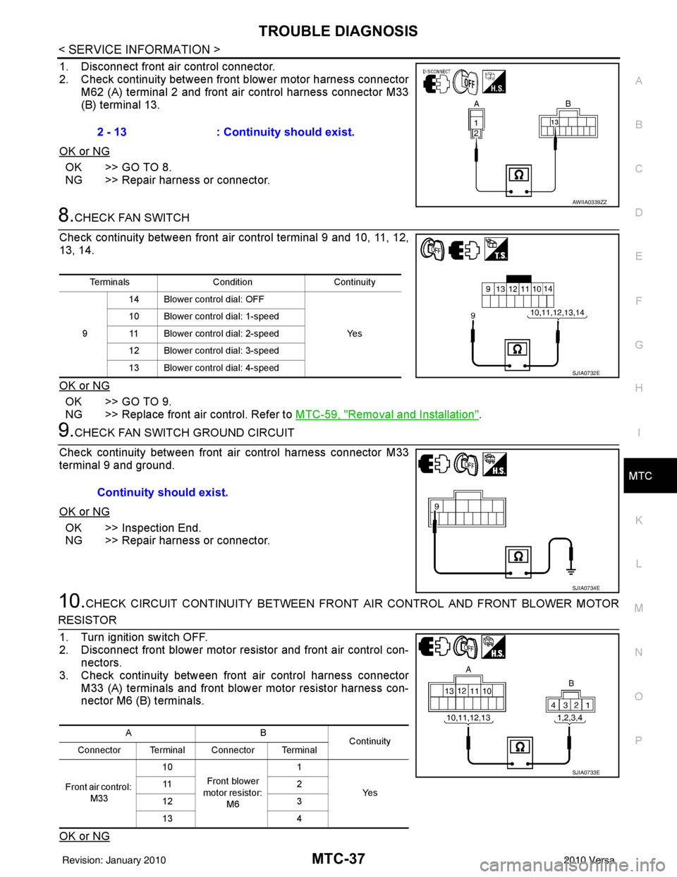
1. Disconnect front air control connector.
2. Check continuity between front blower motor harness connector M62 (A) terminal 2 and front air control harness connector M33
(B) terminal 13.
OK or NG
OK >> GO TO 8.
NG >> Repair harness or connector.
8.CHECK FAN SWITCH
Check continuity between front ai r control terminal 9 and 10, 11, 12,
13, 14.
OK or NG
OK >> GO TO 9.
NG >> Replace front air control. Refer to MTC-59, "
Removal and Installation".
9.CHECK FAN SWITCH GROUND CIRCUIT
Check continuity between front air control harness connector M33
terminal 9 and ground.
OK or NG
OK >> Inspection End.
NG >> Repair harness or connector.
10.CHECK CIRCUIT CONTINUITY BETWEEN FRONT AIR CONTROL AND FRONT BLOWER MOTOR
RESISTOR
1. Turn ignition switch OFF.
2. Disconnect front blower motor resistor and front air control con- nectors.
3. Check continuity between front air control harness connector
M33 (A) terminals and front blower motor resistor harness con-
nector M6 (B) terminals.
OK or NG
2 - 13 : Continuity should exist.
AWIIA0339ZZ
Terminals ConditionContinuity
9 14 Blower control dial: OFF
Ye s
10 Blower control dial: 1-speed
11 Blower control dial: 2-speed
12 Blower control dial: 3-speed
13 Blower control dial: 4-speed
SJIA0732E
Continuity should exist.
SJIA0734E
AB Continuity
Connector Terminal Connector Terminal
Front air control: M33 10
Front blower
motor resistor: M6 1
Ye s
11
2
12 3
13 4
SJIA0733E
Revision: January 20102010 Versa
Page 3317 of 3745
MTC-38
< SERVICE INFORMATION >
TROUBLE DIAGNOSIS
OK >> GO TO 11.
NG >> Repair harness or connector.
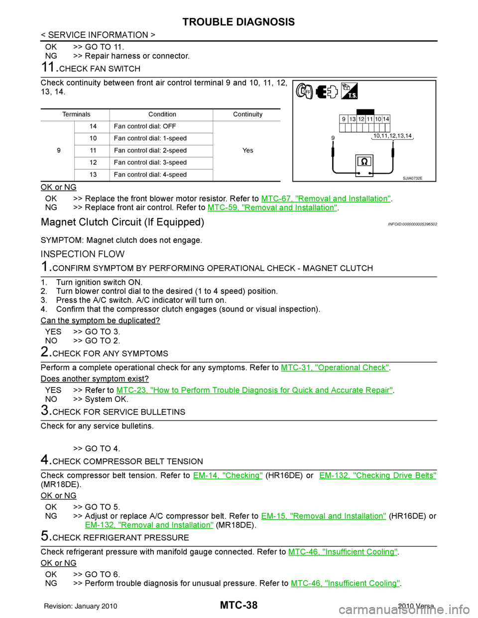
11 .CHECK FAN SWITCH
Check continuity between front air control terminal 9 and 10, 11, 12,
13, 14.
OK or NG
OK >> Replace the front blower motor resistor. Refer to MTC-67, "Removal and Installation".
NG >> Replace front air control. Refer to MTC-59, "
Removal and Installation".
Magnet Clutch Circuit (If Equipped)INFOID:0000000005396502
SYMPTOM: Magnet clutch does not engage.
INSPECTION FLOW
1.CONFIRM SYMPTOM BY PERFORMING OP ERATIONAL CHECK - MAGNET CLUTCH
1. Turn ignition switch ON.
2. Turn blower control dial to the desired (1 to 4 speed) position.
3. Press the A/C switch. A/C indicator will turn on.
4. Confirm that the compressor clut ch engages (sound or visual inspection).
Can the symptom be duplicated?
YES >> GO TO 3.
NO >> GO TO 2.
2.CHECK FOR ANY SYMPTOMS
Perform a complete operational check for any symptoms. Refer to MTC-31, "
Operational Check".
Does another symptom exist?
YES >> Refer to MTC-23, "How to Perform Trouble Diagnosis for Quick and Accurate Repair".
NO >> System OK.
3.CHECK FOR SERVICE BULLETINS
Check for any service bulletins.
>> GO TO 4.
4.CHECK COMPRESSOR BELT TENSION
Check compressor belt tension. Refer to EM-14, "
Checking" (HR16DE) or EM-132, "Checking Drive Belts"
(MR18DE).
OK or NG
OK >> GO TO 5.
NG >> Adjust or replace A/C compressor belt. Refer to EM-15, "
Removal and Installation" (HR16DE) or
EM-132, "
Removal and Installation" (MR18DE).
5.CHECK REFRIGERANT PRESSURE
Check refrigerant pressure with manifold gauge connected. Refer to MTC-46, "
Insufficient Cooling".
OK or NG
OK >> GO TO 6.
NG >> Perform trouble diagnosis for unusual pressure. Refer to MTC-46, "
Insufficient Cooling".
TerminalsConditionContinuity
9 14 Fan control dial: OFF
Ye s
10 Fan control dial: 1-speed
11 Fan control dial: 2-speed
12 Fan control dial: 3-speed
13 Fan control dial: 4-speed
SJIA0732E
Revision: January 20102010 Versa
Page 3318 of 3745
TROUBLE DIAGNOSISMTC-39
< SERVICE INFORMATION >
C
DE
F
G H
I
K L
M A
B
MTC
N
O P
6.CHECK MAGNET CLUTCH CIRCUIT
Perform diagnostic procedure for the magnetic clutch . Refer to "DIAGNOSTIC PROCEDURE FOR MAGNET
CLUTCH".
OK or NG
OK >> If the symptom still exists, perform a complete operational check. Refer to MTC-31, "Operational
Check". If other symptoms exist, refer to MTC-23, "How to Perform Trouble Diagnosis for Quick
and Accurate Repair".
NG >> Repair as necessary.
SYSTEM DESCRIPTION
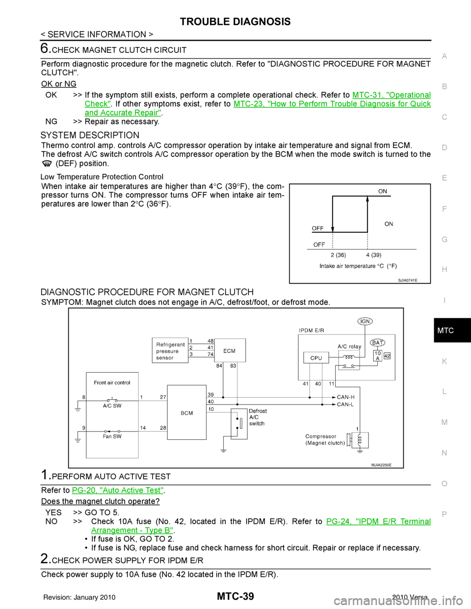
Thermo control amp. controls A/C compressor operation by intake air temperature and signal from ECM.
The defrost A/C switch controls A/C compressor operati on by the BCM when the mode switch is turned to the
(DEF) position.
Low Temperature Protection Control
When intake air temperatures are higher than 4 °C (39° F), the com-
pressor turns ON. The compressor turns OFF when intake air tem-
peratures are lower than 2 °C (36° F).
DIAGNOSTIC PROCEDURE FOR MAGNET CLUTCH
SYMPTOM: Magnet clutch does not engage in A/C, defrost/foot, or defrost mode.
1.PERFORM AUTO ACTIVE TEST
Refer to PG-20, "
Auto Active Test".
Does the magnet clutch operate?
YES >> GO TO 5.
NO >> Check 10A fuse (No. 42, located in the IPDM E/R). Refer to PG-24, "
IPDM E/R Terminal
Arrangement - Type B".
• If fuse is OK, GO TO 2.
• If fuse is NG, replace fuse and check harness for short circuit. Repair or replace if necessary.
2.CHECK POWER SUPPLY FOR IPDM E/R
Check power supply to 10A fuse (No. 42 located in the IPDM E/R).
SJIA0741E
WJIA2250E
Revision: January 20102010 Versa
Page 3319 of 3745
MTC-40
< SERVICE INFORMATION >
TROUBLE DIAGNOSIS
OK or NG
OK >> GO TO 3.
NG >> Check harness for open circuit. Repair or replace if necessary.
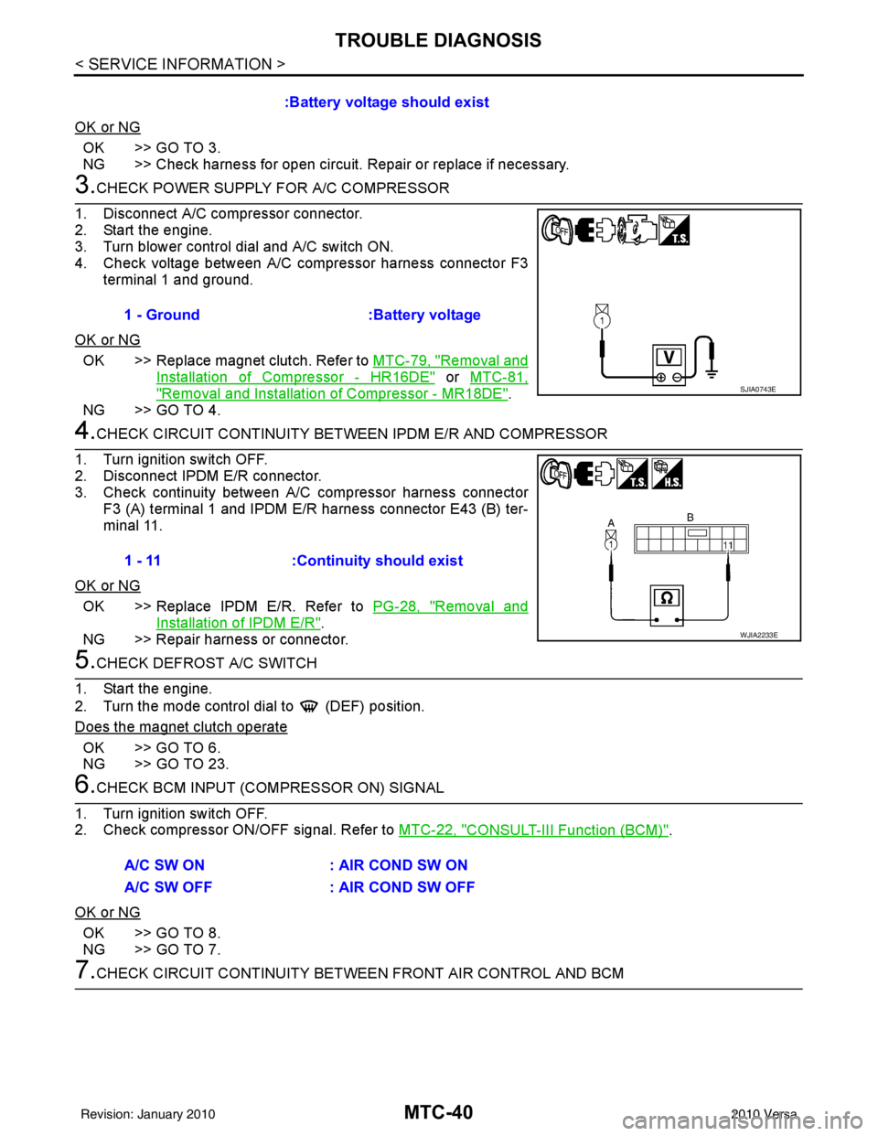
3.CHECK POWER SUPPLY FOR A/C COMPRESSOR
1. Disconnect A/C compressor connector.
2. Start the engine.
3. Turn blower control dial and A/C switch ON.
4. Check voltage between A/C compressor harness connector F3 terminal 1 and ground.
OK or NG
OK >> Replace magnet clutch. Refer to MTC-79, "Removal and
Installation of Compressor - HR16DE" or MTC-81,
"Removal and Installation of Compressor - MR18DE".
NG >> GO TO 4.
4.CHECK CIRCUIT CONTINUITY BETW EEN IPDM E/R AND COMPRESSOR
1. Turn ignition switch OFF.
2. Disconnect IPDM E/R connector.
3. Check continuity between A/ C compressor harness connector
F3 (A) terminal 1 and IPDM E/R harness connector E43 (B) ter-
minal 11.
OK or NG
OK >> Replace IPDM E/R. Refer to PG-28, "Removal and
Installation of IPDM E/R".
NG >> Repair harness or connector.
5.CHECK DEFROST A/C SWITCH
1. Start the engine.
2. Turn the mode control dial to (DEF) position.
Does the magnet clutch operate
OK >> GO TO 6.
NG >> GO TO 23.
6.CHECK BCM INPUT (COMPRESSOR ON) SIGNAL
1. Turn ignition switch OFF.
2. Check compressor ON/OFF signal. Refer to MTC-22, "
CONSULT-III Function (BCM)".
OK or NG
OK >> GO TO 8.
NG >> GO TO 7.
7.CHECK CIRCUIT CONTINUITY BETWEE N FRONT AIR CONTROL AND BCM
:Battery voltage should exist
1 - Ground :Battery voltage
SJIA0743E
1 - 11 :Continuity should exist
WJIA2233E
A/C SW ON : AIR COND SW ON
A/C SW OFF : AIR COND SW OFF
Revision: January 20102010 Versa
Page 3320 of 3745
TROUBLE DIAGNOSISMTC-41
< SERVICE INFORMATION >
C
DE
F
G H
I
K L
M A
B
MTC
N
O P
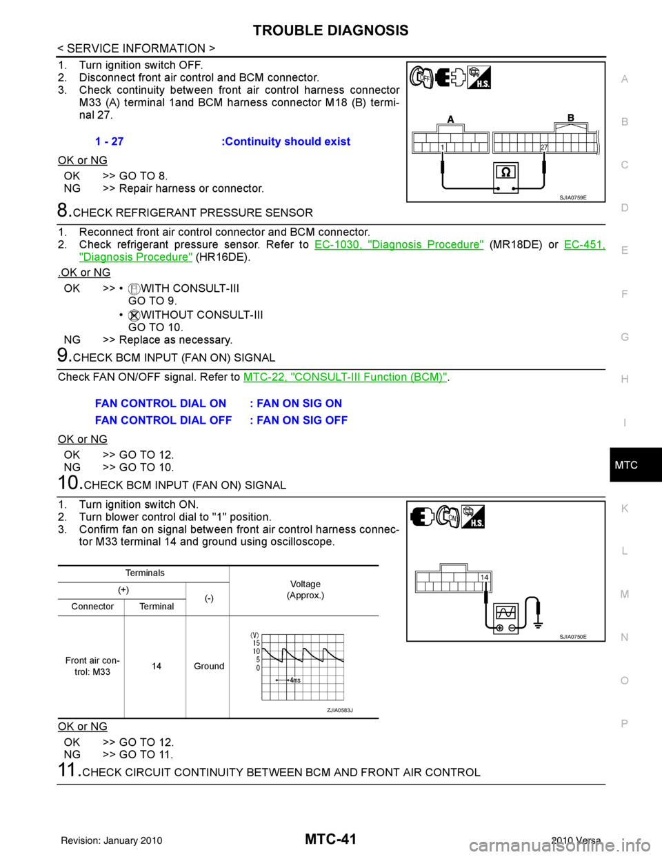
1. Turn ignition switch OFF.
2. Disconnect front air control and BCM connector.
3. Check continuity between front air control harness connector
M33 (A) terminal 1and BCM harness connector M18 (B) termi-
nal 27.
OK or NG
OK >> GO TO 8.
NG >> Repair harness or connector.
8.CHECK REFRIGERANT PRESSURE SENSOR
1. Reconnect front air control connector and BCM connector.
2. Check refrigerant pressure sensor. Refer to EC-1030, "
Diagnosis Procedure" (MR18DE) or EC-451,
"Diagnosis Procedure" (HR16DE).
.OK or NG
OK >> • WITH CONSULT-III GO TO 9.
• WITHOUT CONSULT-III GO TO 10.
NG >> Replace as necessary.
9.CHECK BCM INPUT (FAN ON) SIGNAL
Check FAN ON/OFF signal. Refer to MTC-22, "
CONSULT-III Function (BCM)".
OK or NG
OK >> GO TO 12.
NG >> GO TO 10.
10.CHECK BCM INPUT (FAN ON) SIGNAL
1. Turn ignition switch ON.
2. Turn blower control dial to "1" position.
3. Confirm fan on signal between front air control harness connec- tor M33 terminal 14 and ground using oscilloscope.
OK or NG
OK >> GO TO 12.
NG >> GO TO 11.
11 .CHECK CIRCUIT CONTINUITY BETWEE N BCM AND FRONT AIR CONTROL
1 - 27
:Continuity should exist
SJIA0759E
FAN CONTROL DIAL ON : FAN ON SIG ON
FAN CONTROL DIAL OFF : FAN ON SIG OFF
Te r m i n a l s
Vo l ta g e
(Approx.)
(+)
(-)
Connector Terminal
Front air con- trol: M33 14 Ground
SJIA0750E
ZJIA0583J
Revision: January 20102010 Versa