NISSAN TIIDA 2010 Service Repair Manual
TIIDA 2010
NISSAN
NISSAN
https://www.carmanualsonline.info/img/5/57397/w960_57397-0.png
NISSAN TIIDA 2010 Service Repair Manual
Trending: open gas tank, 1.8L, speed sensor, timing, Lock and security, boot, coolant temperature
Page 3301 of 3745

MTC-22
< SERVICE INFORMATION >
TROUBLE DIAGNOSIS
TROUBLE DIAGNOSIS
CONSULT-III Function (BCM)INFOID:0000000005598079
CONSULT-III can display each diagnostic item using the diagnostic test modes shown following.
ITEMS OF EACH PART
NOTE:
CONSULT-III will only display systems the vehicle possesses.
BCM diagnostic
test item Diagnostic mode
Content
Inspection by part WORK SUPPORT
Supports inspections and adjustments. Commands are transmitted to the BCM for
setting the status suitable for required operation, input/output signals are received
from the BCM and received data is displayed.
DATA MONITOR Displays BCM input/output data in real time. ACTIVE TEST Operation of electrical loads can be checked by sending drive signal to them.
SELF-DIAG RESULTS Displays BCM self-diagnosis results. CAN DIAG SUPPORT MNTR The results of transmit/receive diagnosis of CAN communication can be read.
ECU PART NUMBER BCM part number can be read. CONFIGURATION Performs BCM configuration read/write functions.
System and item CONSULT-III dis-
play Diagnostic test mode (Inspection by part)
WORK
SUPPORT SELF
−
DIAG RE-
SULTS CAN DIAG
SUPPORT
MNTR DATA
MONITOR ECU
PA R T
NUMBER AC-
TIVE
TEST CON-
FIGU-
RATION
BCM BCM×× × × ×
Power door lock sys-
tem DOOR LOCK
×× ×
Rear defogger REAR DEFOG-
GER ××
Warning chime BUZZER ××
Room lamp timer INT LAMP ×× ×
Remote keyless entry
system MULTI REMOTE
ENT
××
×
Headlamp HEAD LAMP×× ×
Wiper WIPER×× ×
Turn signal lamp
Hazard lamp FLASHER
××
Blower fan switch sig-
nal
Air conditioner switch
signal AIR CONDITION-
ER
×
Intelligent Key INTELLIGENT
KEY ×
Combination switch COMB SW ×
NVIS (NATS) IMMU ××
Interior lamp battery
saver BATTERY SAV-
ER
××
×
Back door/Trunk TRUNK ××
Theft alarm THEFT ALARM×× ×
Revision: January 20102010 Versa
Page 3302 of 3745
TROUBLE DIAGNOSISMTC-23
< SERVICE INFORMATION >
C
DE
F
G H
I
K L
M A
B
MTC
N
O P
WORK SUPPORT
Display Item List
How to Perform Trouble Diagnosis for Quick and Accurate RepairINFOID:0000000005396492
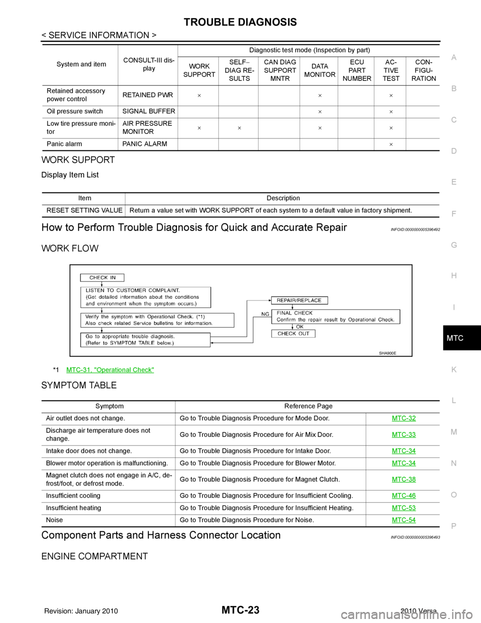
WORK FLOW
SYMPTOM TABLE
Component Parts and Har ness Connector LocationINFOID:0000000005396493
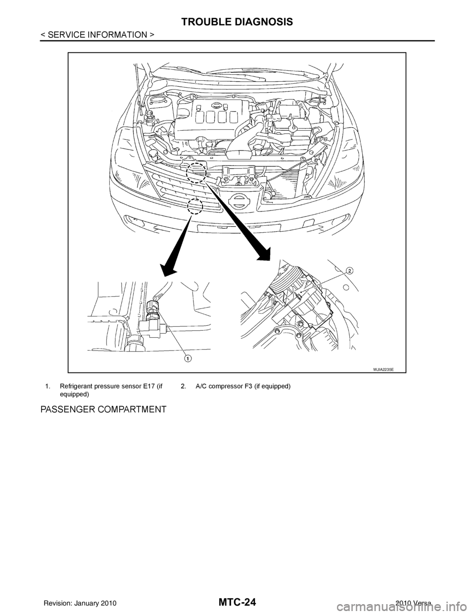
ENGINE COMPARTMENT
Retained accessory
power controlRETAINED PWR
×× ×
Oil pressure switch SIGNAL BUFFER ××
Low tire pressure moni-
tor AIR PRESSURE
MONITOR
××
× ×
Panic alarm PANIC ALARM ×
System and item
CONSULT-III dis-
play Diagnostic test mode (Inspection by part)
WORK
SUPPORT SELF
−
DIAG RE-
SULTS CAN DIAG
SUPPORT
MNTR DATA
MONITOR ECU
PA R T
NUMBER AC-
TIVE
TEST CON-
FIGU-
RATION
Item Description
RESET SETTING VALUE Return a value set with WORK SUPPORT of each system to a default value in factory shipment.
*1 MTC-31, "Operational Check"
SHA900E
Symptom Reference Page
Air outlet does not change. Go to Trouble Diagnosis Procedure for Mode Door. MTC-32
Discharge air temperature does not
change.Go to Trouble Diagnosis Procedure for Air Mix Door.
MTC-33
Intake door does not change.Go to Trouble Diagnosis Procedure for Intake Door. MTC-34
Blower motor operation is malfunctioning. Go to Trouble Diagnosis Procedure for Blower Motor. MTC-34
Magnet clutch does not engage in A/C, de-
frost/foot, or defrost mode.Go to Trouble Diagnosis Procedure for Magnet Clutch.
MTC-38
Insufficient coolingGo to Trouble Diagnosis Procedure for Insufficient Cooling. MTC-46
Insufficient heatingGo to Trouble Diagnosis Procedure for Insufficient Heating. MTC-53
NoiseGo to Trouble Diagnosis Procedure for Noise. MTC-54
Revision: January 20102010 Versa
Page 3303 of 3745
MTC-24
< SERVICE INFORMATION >
TROUBLE DIAGNOSIS
PASSENGER COMPARTMENT
1. Refrigerant pressure sensor E17 (if equipped) 2. A/C compressor F3 (if equipped)
WJIA2235E
Revision: January 20102010 Versa
Page 3304 of 3745
TROUBLE DIAGNOSISMTC-25
< SERVICE INFORMATION >
C
DE
F
G H
I
K L
M A
B
MTC
N
O P
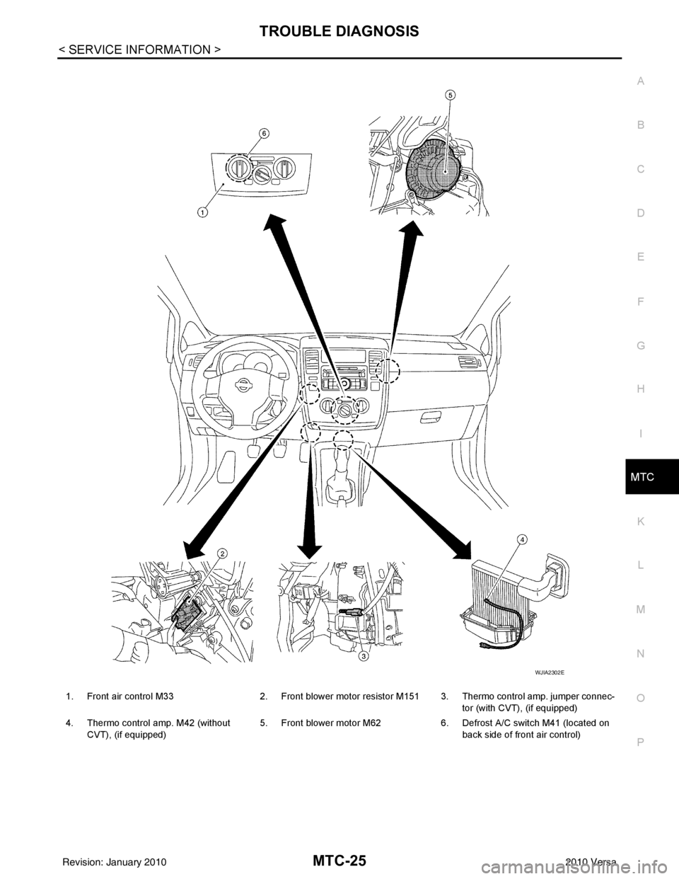
1. Front air control M33 2. Front blower motor resistor M151 3. Thermo control amp. jumper connec-
tor (with CVT), (if equipped)
4. Thermo control amp. M42 (without CVT), (if equipped) 5. Front blower motor M62
6. Defrost A/C switch M41 (located on
back side of front air control)
WJIA2302E
Revision: January 20102010 Versa
Page 3305 of 3745
MTC-26
< SERVICE INFORMATION >
TROUBLE DIAGNOSIS
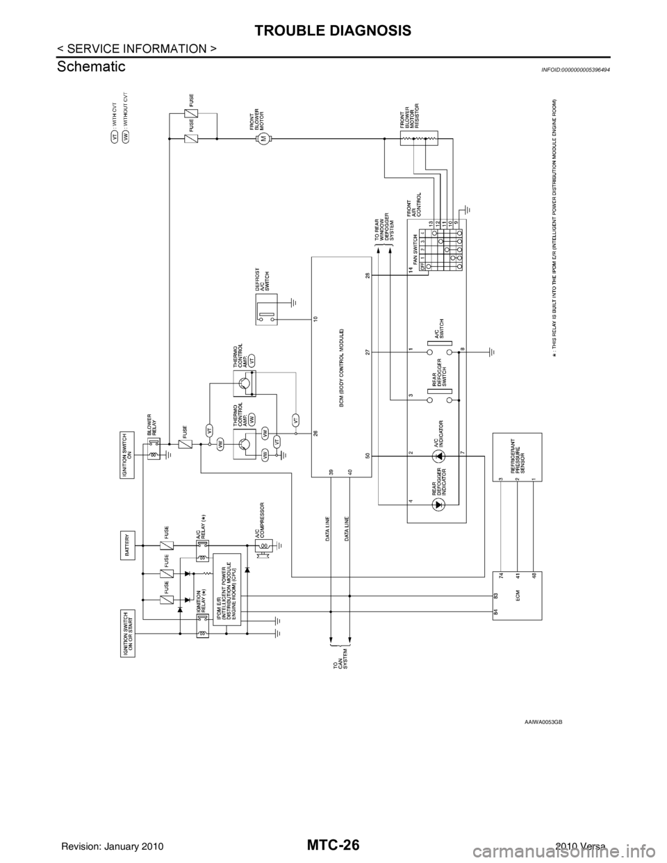
Schematic
INFOID:0000000005396494
AAIWA0053GB
Revision: January 20102010 Versa
Page 3306 of 3745
TROUBLE DIAGNOSISMTC-27
< SERVICE INFORMATION >
C
DE
F
G H
I
K L
M A
B
MTC
N
O P
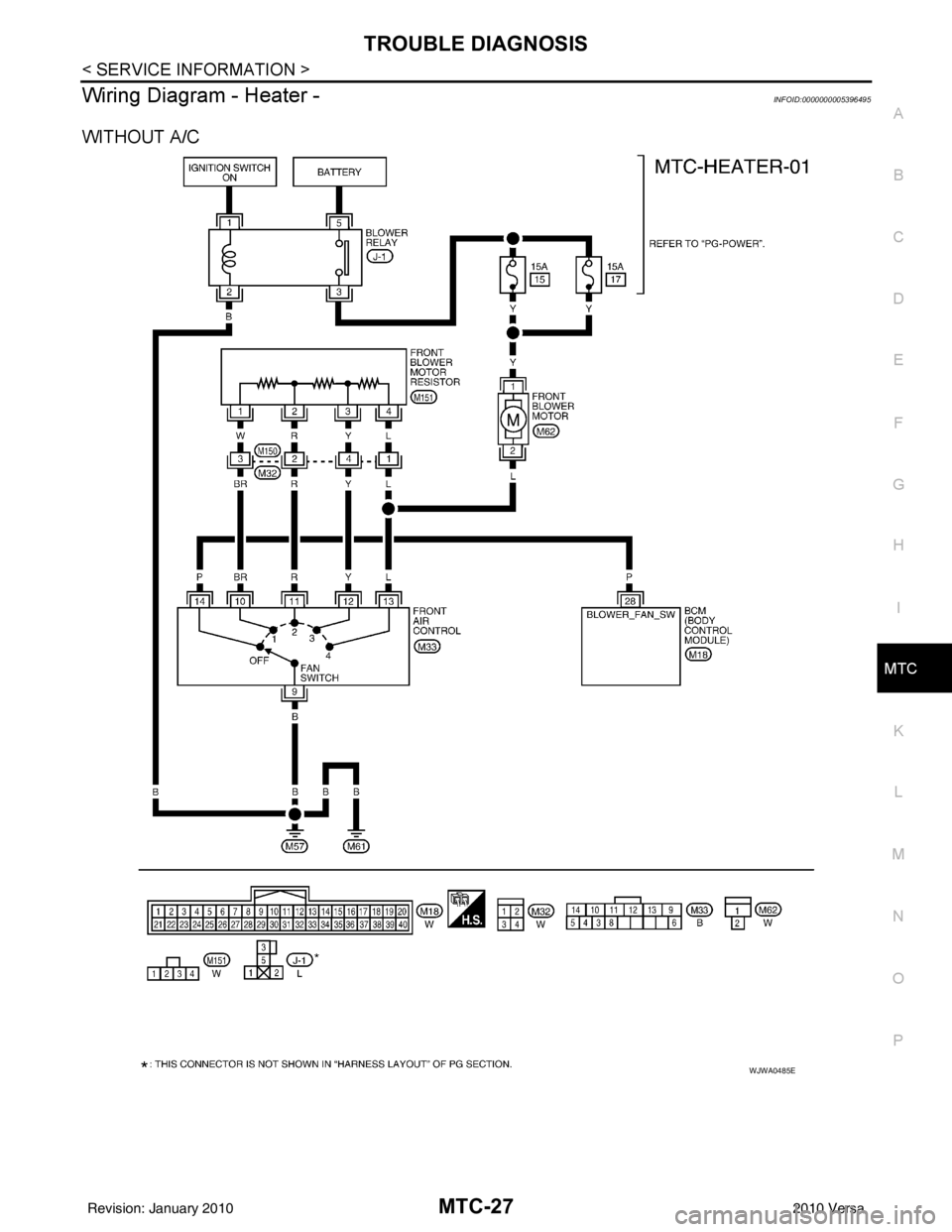
Wiring Diagram - Heater -INFOID:0000000005396495
WITHOUT A/C
WJWA0485E
Revision: January 20102010 Versa
Page 3307 of 3745
MTC-28
< SERVICE INFORMATION >
TROUBLE DIAGNOSIS
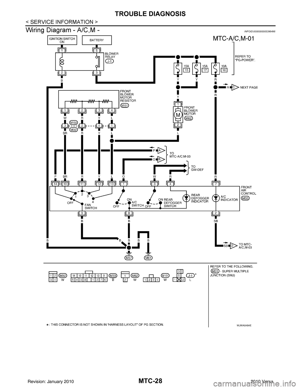
Wiring Diagram - A/C,M -
INFOID:0000000005396496
WJWA0484E
Revision: January 20102010 Versa
Page 3308 of 3745
TROUBLE DIAGNOSISMTC-29
< SERVICE INFORMATION >
C
DE
F
G H
I
K L
M A
B
MTC
N
O P
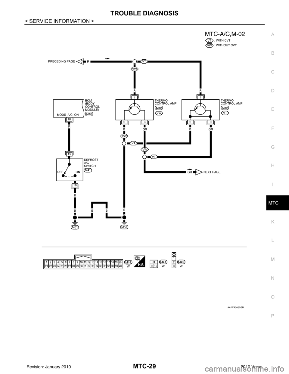
AAIWA0052GB
Revision: January 20102010 Versa
Page 3309 of 3745
MTC-30
< SERVICE INFORMATION >
TROUBLE DIAGNOSIS
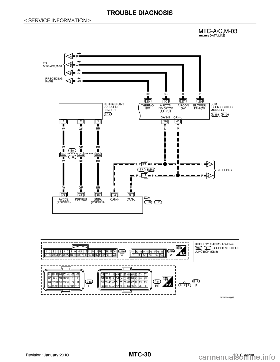
WJWA0488E
Revision: January 20102010 Versa
Page 3310 of 3745
TROUBLE DIAGNOSISMTC-31
< SERVICE INFORMATION >
C
DE
F
G H
I
K L
M A
B
MTC
N
O P
Operational CheckINFOID:0000000005396497
The purpose of the operational check is to confirm that the system operates properly.
CHECKING BLOWER
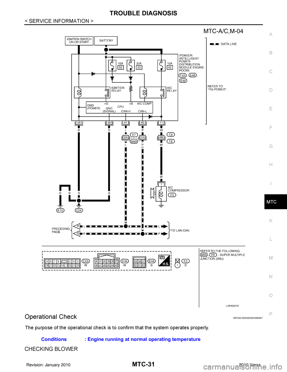
LJWA0021E
Conditions : Engine running at normal operating temperature
Revision: January 20102010 Versa
Trending: brakes, throttle, tire type, remote control, seat adjustment, wiper fluid, adding oil


