NISSAN X-TRAIL 2001 Service Repair Manual
Manufacturer: NISSAN, Model Year: 2001, Model line: X-TRAIL, Model: NISSAN X-TRAIL 2001Pages: 3833, PDF Size: 39.49 MB
Page 2071 of 3833
SHIFT CONTROL
MT-95
D
E
F
G
H
I
J
K
L
MA
B
MT
SHIFT CONTROLPFP:32982
Inspection (RS5F51A)ECS008CC
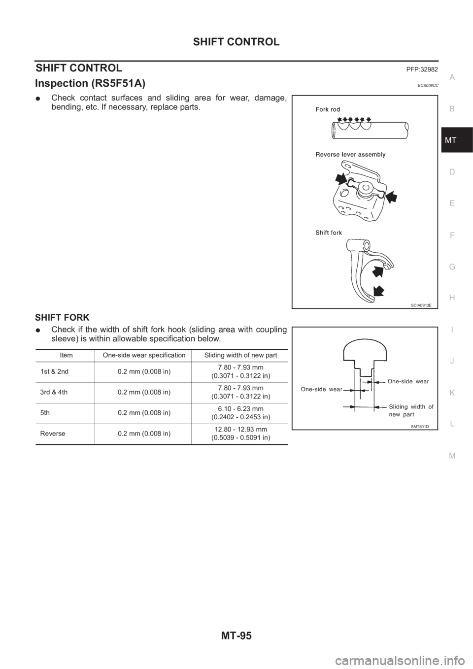
●Check contact surfaces and sliding area for wear, damage,
bending, etc. If necessary, replace parts.
SHIFT FORK
●Check if the width of shift fork hook (sliding area with coupling
sleeve) is within allowable specification below.
SCIA0913E
Item One-side wear specification Sliding width of new part
1st & 2nd 0.2 mm (0.008 in)7.80 - 7.93 mm
(0.3071 - 0.3122 in)
3rd & 4th 0.2 mm (0.008 in)7.80 - 7.93 mm
(0.3071 - 0.3122 in)
5th 0.2 mm (0.008 in)6.10 - 6.23 mm
(0.2402 - 0.2453 in)
Reverse 0.2 mm (0.008 in)12.80 - 12.93 mm
(0.5039 - 0.5091 in)
SMT801D
Page 2072 of 3833
MT-96
SHIFT CONTROL
Inspection (RS6F51A)
ECS008CD
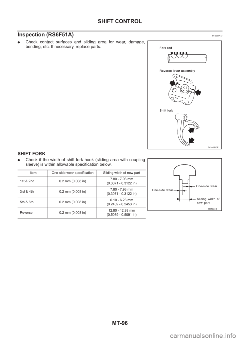
●Check contact surfaces and sliding area for wear, damage,
bending, etc. If necessary, replace parts.
SHIFT FORK
●Check if the width of shift fork hook (sliding area with coupling
sleeve) is within allowable specification below.
SCIA0913E
Item One-side wear specification Sliding width of new part
1st & 2nd 0.2 mm (0.008 in)7.80 - 7.93 mm
(0.3071 - 0.3122 in)
3rd & 4th 0.2 mm (0.008 in)7.80 - 7.93 mm
(0.3071 - 0.3122 in)
5th & 6th 0.2 mm (0.008 in)6.10 - 6.23 mm
(0.2402 - 0.2453 in)
Reverse 0.2 mm (0.008 in)12.80 - 12.93 mm
(0.5039 - 0.5091 in)
SMT801D
Page 2073 of 3833
SERVICE DATA AND SPECIFICATIONS (SDS)
MT-97
D
E
F
G
H
I
J
K
L
MA
B
MT
SERVICE DATA AND SPECIFICATIONS (SDS)PFP:00030
General SpecificationsECS008CE
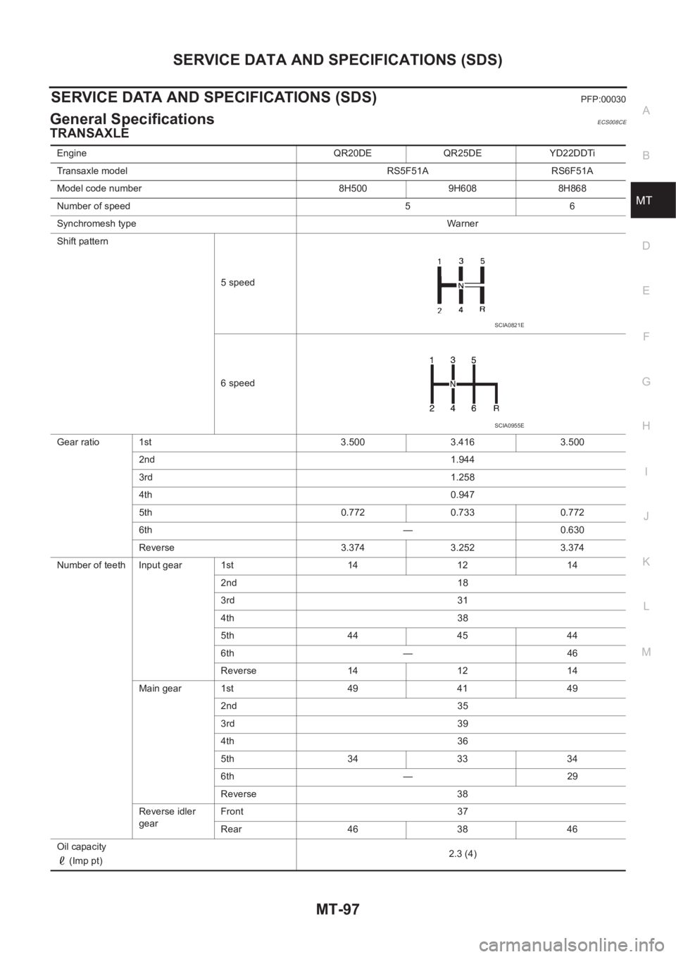
TRANSAXLE
Engine QR20DE QR25DE YD22DDTi
Transaxle model RS5F51A RS6F51A
Model code number 8H500 9H608 8H868
Number of speed 5 6
Synchromesh typeWarner
Shift pattern
5 speed
6 speed
Gear ratio 1st 3.500 3.416 3.500
2nd 1.944
3rd 1.258
4th 0.947
5th 0.772 0.733 0.772
6th — 0.630
Reverse 3.374 3.252 3.374
Number of teeth Input gear 1st 14 12 14
2nd 18
3rd 31
4th 38
5th 444544
6th — 46
Reverse 14 12 14
Main gear 1st 49 41 49
2nd 35
3rd 39
4th 36
5th 343334
6th — 29
Reverse 38
Reverse idler
gearFront 37
Rear 46 38 46
Oil capacity
(Imp pt)2.3 (4)
SCIA0821E
SCIA0955E
Page 2074 of 3833
MT-98
SERVICE DATA AND SPECIFICATIONS (SDS)
FINAL GEAR
Gear End PlayECS008CF
Unit: mm (in)
Clearance Between Baulk Ring and GearECS008CG
3RD,4TH,5TH,6TH & REVERSE BAULK RING
— 6th for RS6F51A Models —
Unit: mm (in)
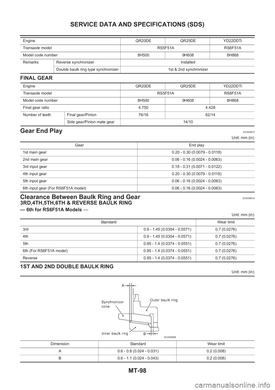
1ST AND 2ND DOUBLE BAULK RING
Unit: mm (in) Remarks Reverse synchronizer Installed
Double baulk ring type synchronizer 1st & 2nd synchronizer Engine QR20DE QR25DE YD22DDTi
Transaxle model RS5F51A RS6F51A
Model code number 8H500 9H608 8H868
Engine QR20DE QR25DE YD22DDTi
Transaxle model RS5F51A RS6F51A
Model code number 8H500 9H608 8H868
Final gear ratio 4.750 4.428
Number of teeth Final gear/Pinion 76/16 62/14
Side gear/Pinion mate gear 14/10
Gear End play
1st main gear0.20 - 0.30 (0.0079 - 0.0118)
2nd main gear 0.06 - 0.16 (0.0024 - 0.0063)
3rd input gear0.18 - 0.31 (0.0071 - 0.0122)
4th input gear0.20 - 0.30 (0.0079 - 0.0118)
5th input gear0.06 - 0.16 (0.0024 - 0.0063)
6th input gear (For RS6F51A model) 0.06 - 0.16 (0.0024 - 0.0063)
Standard Wear limit
3rd 0.9 - 1.45 (0.0354 - 0.0571) 0.7 (0.0276)
4th 0.9 - 1.45 (0.0354 - 0.0571) 0.7 (0.0276)
5th 0.95 - 1.4 (0.0374 - 0.0551) 0.7 (0.0276)
6th (For RS6F51A model) 0.95 - 1.4 (0.0374 - 0.0551) 0.7 (0.0276)
Reverse 0.95 - 1.4 (0.0374 - 0.0551) 0.7 (0.0276)
Dimension Standard Wear limit
A 0.6 - 0.8 (0.024 - 0.031) 0.2 (0.008)
B 0.6 - 1.1 (0.024 - 0.043) 0.2 (0.008)
SCIA0950E
Page 2075 of 3833
SERVICE DATA AND SPECIFICATIONS (SDS)
MT-99
D
E
F
G
H
I
J
K
L
MA
B
MT
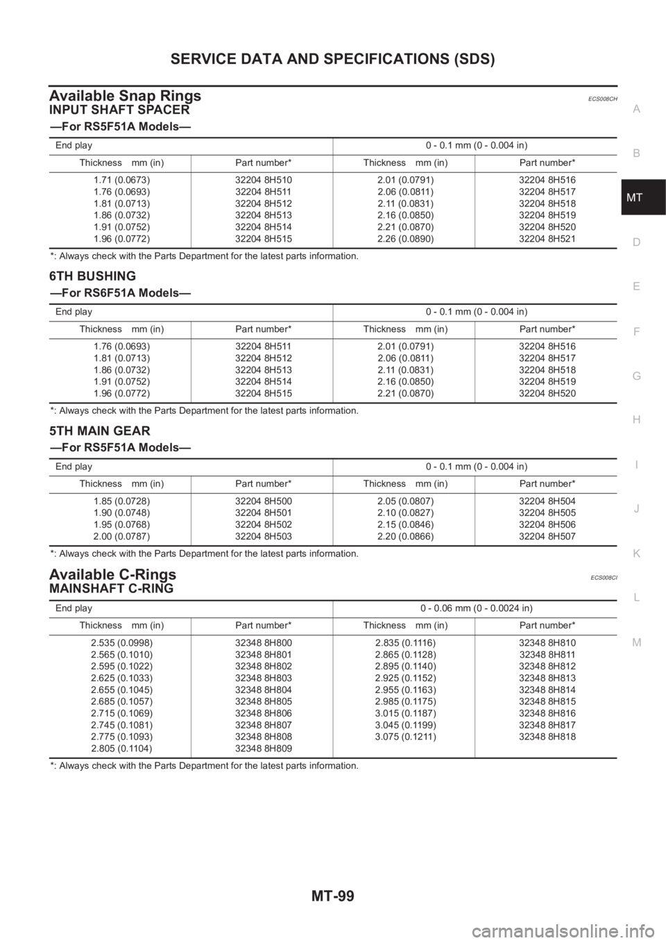
Available Snap RingsECS008CH
INPUT SHAFT SPACER
—For RS5F51A Models—
*: Always check with the Parts Department for the latest parts information.
6TH BUSHING
—For RS6F51A Models—
*: Always check with the Parts Department for the latest parts information.
5TH MAIN GEAR
—For RS5F51A Models—
*: Always check with the Parts Department for the latest parts information.
Available C-RingsECS008CI
MAINSHAFT C-RING
*: Always check with the Parts Department for the latest parts information. End play0 - 0.1 mm (0 - 0.004 in)
Thickness mm (in) Part number* Thickness mm (in) Part number*
1.71 (0.0673)
1.76 (0.0693)
1.81 (0.0713)
1.86 (0.0732)
1.91 (0.0752)
1.96 (0.0772)32204 8H510
32204 8H511
32204 8H512
32204 8H513
32204 8H514
32204 8H5152.01 (0.0791)
2.06 (0.0811)
2.11 (0.0831)
2.16 (0.0850)
2.21 (0.0870)
2.26 (0.0890)32204 8H516
32204 8H517
32204 8H518
32204 8H519
32204 8H520
32204 8H521
End play0 - 0.1 mm (0 - 0.004 in)
Thickness mm (in) Part number* Thickness mm (in) Part number*
1.76 (0.0693)
1.81 (0.0713)
1.86 (0.0732)
1.91 (0.0752)
1.96 (0.0772)32204 8H511
32204 8H512
32204 8H513
32204 8H514
32204 8H5152.01 (0.0791)
2.06 (0.0811)
2.11 (0.0831)
2.16 (0.0850)
2.21 (0.0870)32204 8H516
32204 8H517
32204 8H518
32204 8H519
32204 8H520
End play0 - 0.1 mm (0 - 0.004 in)
Thickness mm (in) Part number* Thickness mm (in) Part number*
1.85 (0.0728)
1.90 (0.0748)
1.95 (0.0768)
2.00 (0.0787)32204 8H500
32204 8H501
32204 8H502
32204 8H5032.05 (0.0807)
2.10 (0.0827)
2.15 (0.0846)
2.20 (0.0866)32204 8H504
32204 8H505
32204 8H506
32204 8H507
End play0 - 0.06 mm (0 - 0.0024 in)
Thickness mm (in) Part number* Thickness mm (in) Part number*
2.535 (0.0998)
2.565 (0.1010)
2.595 (0.1022)
2.625 (0.1033)
2.655 (0.1045)
2.685 (0.1057)
2.715 (0.1069)
2.745 (0.1081)
2.775 (0.1093)
2.805 (0.1104)32348 8H800
32348 8H801
32348 8H802
32348 8H803
32348 8H804
32348 8H805
32348 8H806
32348 8H807
32348 8H808
32348 8H8092.835 (0.1116)
2.865 (0.1128)
2.895 (0.1140)
2.925 (0.1152)
2.955 (0.1163)
2.985 (0.1175)
3.015 (0.1187)
3.045 (0.1199)
3.075 (0.1211)32348 8H810
32348 8H811
32348 8H812
32348 8H813
32348 8H814
32348 8H815
32348 8H816
32348 8H817
32348 8H818
Page 2076 of 3833
MT-100
SERVICE DATA AND SPECIFICATIONS (SDS)
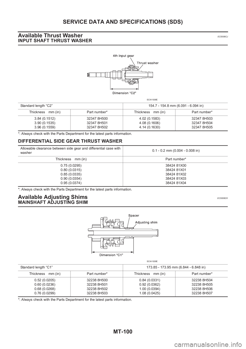
Available Thrust Washer
ECS008CJ
INPUT SHAFT THRUST WASHER
*: Always check with the Parts Department for the latest parts information.
DIFFERENTIAL SIDE GEAR THRUST WASHER
*: Always check with the Parts Department for the latest parts information.
Available Adjusting ShimsECS008CK
MAINSHAFT ADJUSTING SHIM
*: Always check with the Parts Department for the latest parts information. Standard length “C2” 154.7 - 154.8 mm (6.091 - 6.094 in)
Thickness mm (in) Part number* Thickness mm (in) Part number*
3.84 (0.1512)
3.90 (0.1535)
3.96 (0.1559)32347 8H500
32347 8H501
32347 8H5024.02 (0.1583)
4.08 (0.1606)
4.14 (0.1630)32347 8H503
32347 8H504
32347 8H505
SCIA1008E
Allowable clearance between side gear and differential case with
washer0.1 - 0.2 mm (0.004 - 0.008 in)
Thickness mm (in) Part number*
0.75 (0.0295)
0.80 (0.0315)
0.85 (0.0335)
0.90 (0.0354)
0.95 (0.0374)38424 81X00
38424 81X01
38424 81X02
38424 81X03
38424 81X04
Standard length “C1” 173.85 - 173.95 mm (6.844 - 6.848 in)
Thickness mm (in) Part number* Thickness mm (in) Part number*
0.52 (0.0205)
0.60 (0.0236)
0.68 (0.0268)
0.76 (0.0299)32238 8H500
32238 8H501
32238 8H502
32238 8H5030.84 (0.0331)
0.92 (0.0362)
1.00 (0.0394)
1.08 (0.0425)32238 8H504
32238 8H505
32238 8H506
32238 8H507
SCIA1009E
Page 2077 of 3833
SERVICE DATA AND SPECIFICATIONS (SDS)
MT-101
D
E
F
G
H
I
J
K
L
MA
B
MT
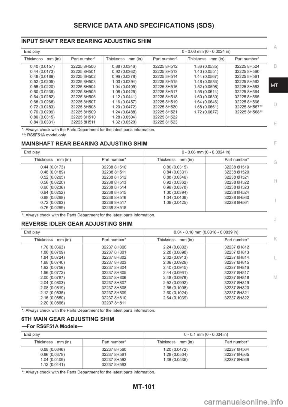
INPUT SHAFT REAR BEARING ADJUSTING SHIM
*: Always check with the Parts Department for the latest parts information.
**: RS5F51A model only.
MAINSHAFT REAR BEARING ADJUSTING SHIM
*: Always check with the Parts Department for the latest parts information.
REVERSE IDLER GEAR ADJUSTING SHIM
*: Always check with the Parts Department for the latest parts information.
6TH MAIN GEAR ADJUSTING SHIM
—For RS6F51A Models—
*: Always check with the Parts Department for the latest parts information. End play0 - 0.06 mm (0 - 0.0024 in)
Thickness mm (in) Part number* Thickness mm (in) Part number* Thickness mm (in) Part number*
0.40 (0.0157)
0.44 (0.0173)
0.48 (0.0189)
0.52 (0.0205)
0.56 (0.0220)
0.60 (0.0236)
0.64 (0.0252)
0.68 (0.0268)
0.72 (0.0283)
0.76 (0.0299)
0.80 (0.0315)
0.84 (0.0331)32225 8H500
32225 8H501
32225 8H502
32225 8H503
32225 8H504
32225 8H505
32225 8H506
32225 8H507
32225 8H508
32225 8H509
32225 8H510
32225 8H5110.88 (0.0346)
0.92 (0.0362)
0.96 (0.0378)
1.00 (0.0394)
1.04 (0.0409)
1.08 (0.0425)
1.12 (0.0441)
1.16 (0.0457)
1.20 (0.0472)
1.24 (0.0488)
1.28 (0.0504)
1.32 (0.0520)32225 8H512
32225 8H513
32225 8H514
32225 8H515
32225 8H516
32225 8H517
32225 8H518
32225 8H519
32225 8H520
32225 8H521
32225 8H522
32225 8H5231.36 (0.0535)
1.40 (0.0551)
1.44 (0.0567)
1.48 (0.0583)
1.52 (0.0598)
1.56 (0.0614)
1.60 (0.0630)
1.64 (0.0646)
1.68 (0.0661)
1.72 (0.0677)32225 8H524
32225 8H560
32225 8H561
32225 8H562
32225 8H563
32225 8H564
32225 8H565
32225 8H566
32225 8H567**
32225 8H568**
End play0 - 0.06 mm (0 - 0.0024 in)
Thickness mm (in) Part number* Thickness mm (in) Part number*
0.44 (0.0173)
0.48 (0.0189)
0.52 (0.0205)
0.56 (0.0220)
0.60 (0.0236)
0.64 (0.0252)
0.68 (0.0268)
0.72 (0.0283)
0.76 (0.0299)32238 8H510
32238 8H511
32238 8H512
32238 8H513
32238 8H514
32238 8H515
32238 8H516
32238 8H517
32238 8H5180.80 (0.0315)
0.84 (0.0331)
0.88 (0.0346)
0.92 (0.0362)
0.96 (0.0378)
1.00 (0.0394)
1.04 (0.0409)
1.08 (0.0425)32238 8H519
32238 8H520
32238 8H521
32238 8H522
32238 8H523
32238 8H524
32238 8H560
32238 8H561
End play0.04 - 0.10 mm (0.0016 - 0.0039 in)
Thickness mm (in) Part number* Thickness mm (in) Part number*
1.76 (0.0693)
1.80 (0.0709)
1.84 (0.0724)
1.88 (0.0740)
1.92 (0.0756)
1.96 (0.0772)
2.00 (0.0787)
2.04 (0.0803)
2.08 (0.0819)
2.12 (0.0835)
2.16 (0.0850)
2.20 (0.0866)32237 8H800
32237 8H801
32237 8H802
32237 8H803
32237 8H804
32237 8H805
32237 8H806
32237 8H807
32237 8H808
32237 8H809
32237 8H810
32237 8H8112.24 (0.0882)
2.28 (0.0898)
2.32 (0.0913)
2.36 (0.0929)
2.40 (0.0945)
2.44 (0.0961)
2.48 (0.0976)
2.52 (0.0992)
2.56 (0.1008)
2.60 (0.1024)
2.64 (0.1039)32237 8H812
32237 8H813
32237 8H814
32237 8H815
32237 8H816
32237 8H817
32237 8H818
32237 8H819
32237 8H820
32237 8H821
32237 8H822
End play0 - 0.1 mm (0 - 0.004 in)
Thickness mm (in) Part number* Thickness mm (in) Part number*
0.88 (0.0346)
0.96 (0.0378)
1.04 (0.0409)
1.12 (0.0441)32237 8H560
32237 8H561
32237 8H562
32237 8H5631.20 (0.0472)
1.28 (0.0504)
1.36 (0.0535)32237 8H564
32237 8H565
32237 8H566
Page 2078 of 3833
MT-102
SERVICE DATA AND SPECIFICATIONS (SDS)
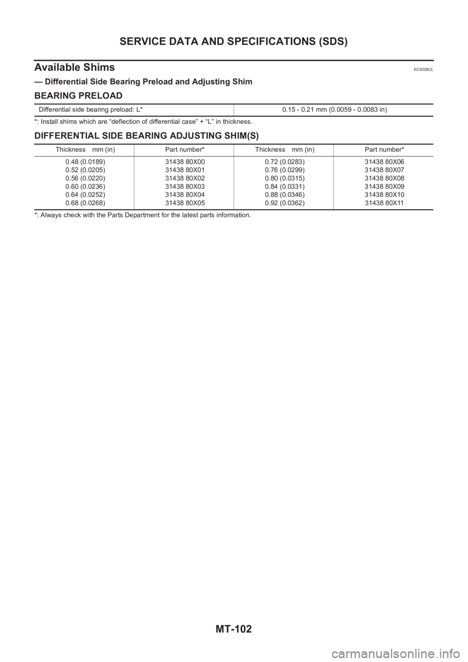
Available Shims
ECS008CL
— Differential Side Bearing Preload and Adjusting Shim
BEARING PRELOAD
*: Install shims which are “deflection of differential case” + “L” in thickness.
DIFFERENTIAL SIDE BEARING ADJUSTING SHIM(S)
*: Always check with the Parts Department for the latest parts information. Differential side bearing preload: L* 0.15 - 0.21 mm (0.0059 - 0.0083 in)
Thickness mm (in) Part number* Thickness mm (in) Part number*
0.48 (0.0189)
0.52 (0.0205)
0.56 (0.0220)
0.60 (0.0236)
0.64 (0.0252)
0.68 (0.0268)31438 80X00
31438 80X01
31438 80X02
31438 80X03
31438 80X04
31438 80X050.72 (0.0283)
0.76 (0.0299)
0.80 (0.0315)
0.84 (0.0331)
0.88 (0.0346)
0.92 (0.0362)31438 80X06
31438 80X07
31438 80X08
31438 80X09
31438 80X10
31438 80X11
Page 2079 of 3833
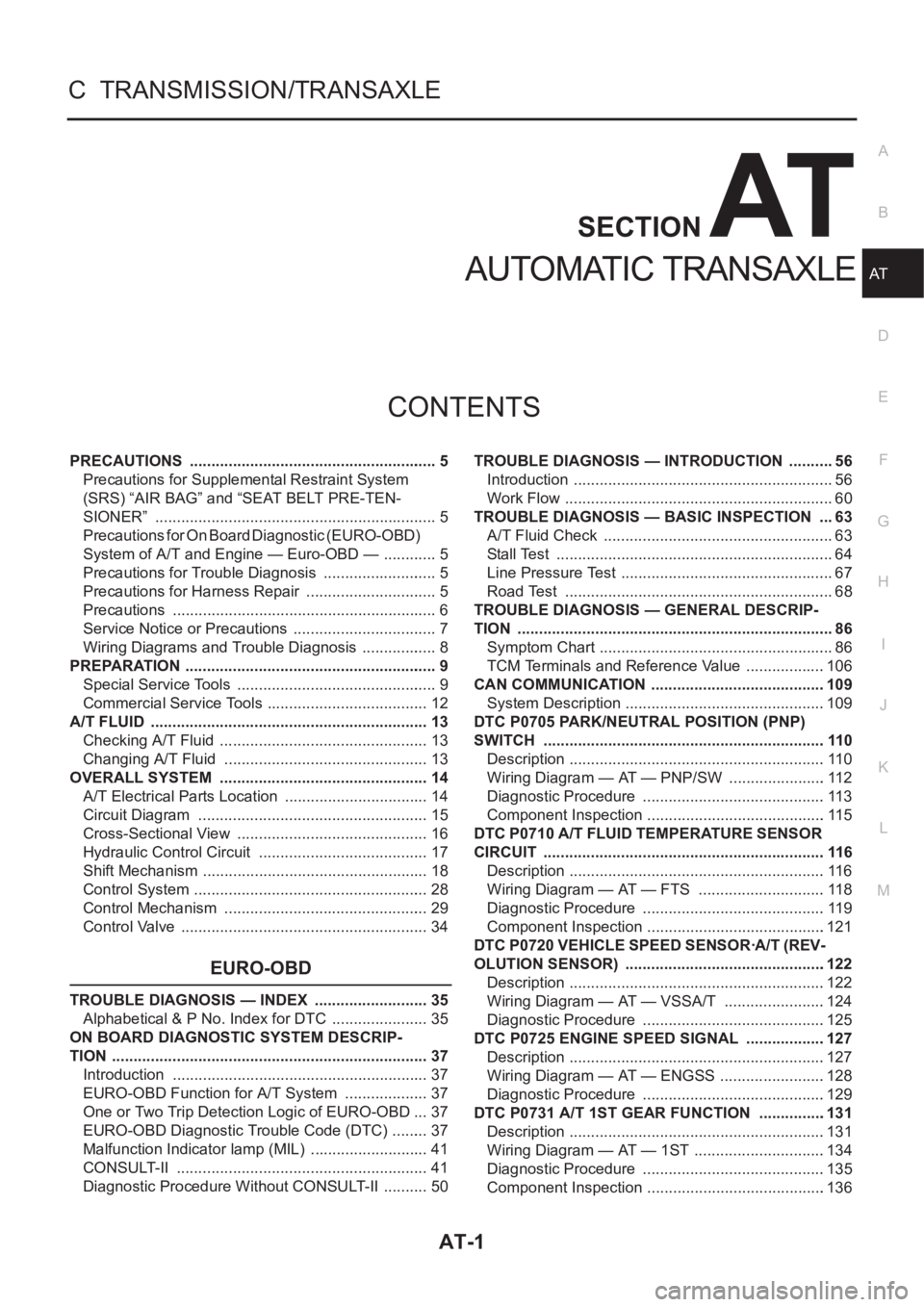
AT-1
AUTOMATIC TRANSAXLE
C TRANSMISSION/TRANSAXLE
CONTENTS
D
E
F
G
H
I
J
K
L
M
SECTION
A
B
AT
AUTOMATIC TRANSAXLE
PRECAUTIONS .......................................................... 5
Precautions for Supplemental Restraint System
(SRS) “AIR BAG” and “SEAT BELT PRE-TEN-
SIONER” .................................................................. 5
Precautions for On Board Diagnostic (EURO-OBD)
System of A/T and Engine — Euro-OBD — ............. 5
Precautions for Trouble Diagnosis ........................... 5
Precautions for Harness Repair ............................... 5
Precautions .............................................................. 6
Service Notice or Precautions .................................. 7
Wiring Diagrams and Trouble Diagnosis .................. 8
PREPARATION ........................................................... 9
Special Service Tools ............................................... 9
Commercial Service Tools ...................................... 12
A/T FLUID ................................................................. 13
Checking A/T Fluid ................................................. 13
Changing A/T Fluid ............................................. ... 13
OVERALL SYSTEM ................................................. 14
A/T Electrical Parts Location .................................. 14
Circuit Diagram ...................................................... 15
Cross-Sectional View ............................................. 16
Hydraulic Control Circuit ........................................ 17
Shift Mechanism ..................................................... 18
Control System ....................................................... 28
Control Mechanism ................................................ 29
Control Valve .......................................................... 34
EURO-OBD
TROUBLE DIAGNOSIS — INDEX ........................... 35
Alphabetical & P No. Index for DTC ....................... 35
ON BOARD DIAGNOSTIC SYSTEM DESCRIP-
TION .......................................................................... 37
Introduction ............................................................ 37
EURO-OBD Function for A/T System .................... 37
One or Two Trip Detection Logic of EURO-OBD ... 37
EURO-OBD Diagnostic Trouble Code (DTC) ......... 37
Malfunction Indicator lamp (MIL) ............................ 41
CONSULT-II ........................................................... 41
Diagnostic Procedure Without CONSULT-II ........... 50TROUBLE DIAGNOSIS — INTRODUCTION ........... 56
Introduction ............................................................. 56
Work Flow ............................................................... 60
TROUBLE DIAGNOSIS — BASIC INSPECTION .... 63
A/T Fluid Check ...................................................... 63
Stall Test ................................................................. 64
Line Pressure Test .................................................. 67
Road Test ............................................................... 68
TROUBLE DIAGNOSIS — GENERAL DESCRIP-
TION .......................................................................... 86
Symptom Chart ....................................................... 86
TCM Terminals and Reference Value ...................106
CAN COMMUNICATION .........................................109
System Description ...............................................109
DTC P0705 PARK/NEUTRAL POSITION (PNP)
SWITCH ..................................................................110
Description ............................................................110
Wiring Diagram — AT — PNP/SW .......................112
Diagnostic Procedure ...........................................113
Component Inspection ..........................................115
DTC P0710 A/T FLUID TEMPERATURE SENSOR
CIRCUIT ..................................................................116
Description ............................................................116
Wiring Diagram — AT — FTS ..............................118
Diagnostic Procedure ...........................................119
Component Inspection ..........................................121
DTC P0720 VEHICLE SPEED SENSOR·A/T (REV-
OLUTION SENSOR) ...............................................122
Description ............................................................122
Wiring Diagram — AT — VSSA/T ........................124
Diagnostic Procedure ...........................................125
DTC P0725 ENGINE SPEED SIGNAL ...................127
Description ............................................................127
Wiring Diagram — AT — ENGSS .........................128
Diagnostic Procedure ...........................................129
DTC P0731 A/T 1ST GEAR FUNCTION ...............
.131
Description ............................................................131
Wiring Diagram — AT — 1ST ...............................134
Diagnostic Procedure ...........................................135
Component Inspection ..........................................136
Page 2080 of 3833
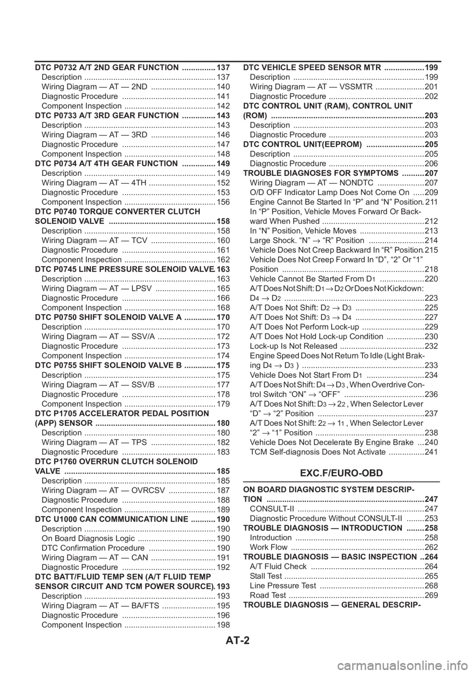
AT-2
DTC P0732 A/T 2ND GEAR FUNCTION ................137
Description ............................................................137
Wiring Diagram — AT — 2ND ..............................140
Diagnostic Procedure ...........................................141
Component Inspection ..........................................142
DTC P0733 A/T 3RD GEAR FUNCTION ................143
Description ............................................................143
Wiring Diagram — AT — 3RD ..............................146
Diagnostic Procedure ...........................................147
Component Inspection ..........................................148
DTC P0734 A/T 4TH GEAR FUNCTION ................149
Description ............................................................149
Wiring Diagram — AT — 4TH ...............................152
Diagnostic Procedure ...........................................153
Component Inspection ..........................................156
DTC P0740 TORQUE CONVERTER CLUTCH
SOLENOID VALVE .................................................158
Description ............................................................158
Wiring Diagram — AT — TCV ..............................160
Diagnostic Procedure ...........................................161
Component Inspection ..........................................162
DTC P0745 LINE PRESSURE SOLENOID VALVE .163
Description ............................................................163
Wiring Diagram — AT — LPSV ............................165
Diagnostic Procedure ...........................................166
Component Inspection ..........................................168
DTC P0750 SHIFT SOLENOID VALVE A ...............170
Description ............................................................170
Wiring Diagram — AT — SSV/A ...........................172
Diagnostic Procedure ...........................................173
Component Inspection ..........................................174
DTC P0755 SHIFT SOLENOID VALVE B ...............175
Description ............................................................175
Wiring Diagram — AT — SSV/B ...........................177
Diagnostic Procedure ...........................................178
Component Inspection ..........................................179
DTC P1705 ACCELERATOR PEDAL POSITION
(APP) SENSOR .......................................................180
Description ............................................................180
Wiring Diagram — AT — TPS ..............................182
Diagnostic Procedure ...........................................183
DTC P1760 OVERRUN CLUTCH SOLENOID
VALVE .....................................................................185
Description ............................................................185
Wiring Diagram — AT — OVRCSV ......................187
Diagnostic Procedure ...........................................188
Component Inspection ..........................................189
DTC U1000 CAN COMMUNICATION LINE ...........
.190
Description ............................................................190
On Board Diagnosis Logic ....................................190
DTC Confirmation Procedure ...............................190
Wiring Diagram — AT — CAN ..............................191
Diagnostic Procedure ...........................................192
DTC BATT/FLUID TEMP SEN (A/T FLUID TEMP
SENSOR CIRCUIT AND TCM POWER SOURCE) .193
Description ............................................................193
Wiring Diagram — AT — BA/FTS .........................195
Diagnostic Procedure ...........................................196
Component Inspection ..........................................198DTC VEHICLE SPEED SENSOR MTR ...................199
Description ............................................................199
Wiring Diagram — AT — VSSMTR .......................201
Diagnostic Procedure ............................................202
DTC CONTROL UNIT (RAM), CONTROL UNIT
(ROM) ......................................................................203
Description ............................................................203
Diagnostic Procedure ............................................203
DTC CONTROL UNIT(EEPROM) ...........................205
Description ............................................................205
Diagnostic Procedure ............................................206
TROUBLE DIAGNOSES FOR SYMPTOMS ...........207
Wiring Diagram — AT — NONDTC ......................207
O/D OFF Indicator Lamp Does Not Come On ......209
Engine Cannot Be Started In “P” and “N” Position .211
In “P” Position, Vehicle Moves Forward Or Back-
ward When Pushed ...............................................212
In “N” Position, Vehicle Moves ..............................213
Large Shock. “N” → “R” Position ..........................214
Vehicle Does Not Creep Backward In “R” Position .215
Vehicle Does Not Creep Forward In “D”, “2” Or “1”
Position .................................................................218
Vehicle Cannot Be Started From D
1 .....................220
A/T Does Not Shift: D
1→ D2 Or Does Not Kickdown:
D
4→ D2 ...............................................................
.223
A/T Does Not Shift: D
2→ D3 ................................225
A/T Does Not Shift: D
3→ D4 ................................227
A/T Does Not Perform Lock-up .............................229
A/T Does Not Hold Lock-up Condition ..................230
Lock-up Is Not Released .......................................232
Engine Speed Does Not Return To Idle (Light Brak-
ing D
4→ D3 ) ........................................................233
Vehicle Does Not Start From D
1 ...........................234
A / T D o e s N o t S h i f t : D
4→ D3 , W h e n O v e r d r i v e C o n -
trol Switch “ON” → “OFF” .....................................236
A/T Does Not Shift: D
3→ 22 , W h e n S e l e c t o r L e v e r
“D” → “2” Position .................................................237
A/T Does Not Shift: 2
2→ 11 , When Selector Lever
“2” → “1” Position ..................................................238
Vehicle Does Not Decelerate By Engine Brake ....240
TCM Self-diagnosis Does Not Activate .................241
EXC.F/EURO-OBD
ON BOARD DIAGNOSTIC SYSTEM DESCRIP-
TION ........................................................................247
CONSULT-II ..........................................................247
Diagnostic Procedure Without CONSULT-II .........253
TROUBLE DIAGNOSIS — INTRODUCTION .........258
Introduction ...........................................................258
Work Flow .............................................................262
TROUBLE DIAGNOSIS — BASIC INSPECTION ...264
A/T Fluid Check ....................................................264
Stall Test ................................................................265
Line Pressure Test ................................................268
Road Test ..............................................................269
TROUBLE DIAGNOSIS — GENERAL DESCRIP-