brake rotor NISSAN X-TRAIL 2001 Service Owner's Manual
[x] Cancel search | Manufacturer: NISSAN, Model Year: 2001, Model line: X-TRAIL, Model: NISSAN X-TRAIL 2001Pages: 3833, PDF Size: 39.49 MB
Page 2788 of 3833

BRC-4
[4WD/ABS]
PRECAUTIONS
[4WD/ABS]PRECAUTIONSPFP:00001
Precautions for brake systemEFS001B6
●Recommended fluid is brake fluid “DOT 3 ”or “DOT 4”.
●Never reuse drained brake fluid.
●Be careful not to splash brake fluid on painted areas.
●To clean or wash all parts of master cylinder, disc brake caliper and wheel cylinder, use clean brake fluid.
●Never use mineral oils such as gasoline or kerosene. They will ruin rubber parts of the hydraulic system.
●Use flare nut wrench when removing and installing brake tube.
●Always torque brake lines when installing.
●Burnish the brake contact surfaces after refinishing or replacing
drums or rotors, after replacing pads or linings, or if a soft pedal
occurs at very low mileage. Refer to BR-10, "
Brake Burnishing
Procedure" .
●Before working, turn OFF ignition switch. Disconnect connectors
for ABS actuator and control module or battery terminals.
WARNING:
●Clean brake pads and shoes with a waste cloth, then wipe
with a dust collector.
Precautions for brake controlEFS001B7
●If malfunction is indicated by 4WD warning lamp and/or ABS warning lamp, collect necessary information
from customer (what symptoms are present under what conditions). Find out possible causes before start-
ing service. Besides electrical system inspection, check operation of ABS actuator.
●If malfunction is detected, proceed to trouble diagnosis after checking tire pressure and tire wear.
●Stopping distance or steering stability may be deteriorated by the following conditions. Tire size and type
are in improper combination. Brake pads are not Nissan genuine parts.
●Fitting tires of different size on vehicle can be cause of longitudinal vibration. Always use tires of the same
size and brand. Exchange front and rear tires on the following conditions: Longitudinal vibration occurs in
vehicle with tires of the same size and brand. After replacement, perform trouble diagnosis. 1580|None
●4WD/ABS function may have a failure or error under following condition: There is radio, antenna, or
antenna lead-in wire (including wiring) near control module.
●If aftermarket parts (e.g. Car stereo equipment, CD player) have been installed, check electrical har-
nesses for pinches, open, and improper wiring.
SBR820BA
Page 2838 of 3833

BRC-54
[ESP/TCS/ABS]
PRECAUTIONS
[ESP/TCS/ABS]PRECAUTIONSPFP:00001
Precautions for Brake SystemEFS0019O
●Recommended fluid is brake fluid “DOT 3” or “DOT 4”.
●Never reuse drained brake fluid.
●Be careful not to splash brake fluid on painted areas; it may cause paint damage. If brake fluid is splashed
on painted areas, wash it away with water immediately.
●Never use mineral oils such as gasoline or kerosene. They will ruin rubber parts of hydraulic system.
●Use flare nut wrench when removing and installing brake tubes.
●Always torque brake lines when installing.
●Before working, turn the ignition switch OFF and disconnect the
connectors for the ESP/TCS/ABS actuator and control unit or
the battery terminals.
●Burnish the brake contact surfaces after refinishing or replacing
drums or rotors, after replacing pads or linings, or if a soft pedal
occurs at very low mileage. Refer to BR-10, "
Brake Burnishing
Procedure" .
WARNING:
Clean brakes with a vacuum dust collector to minimize risk
of health hazard from powder caused by friction.
Precautions for Brake ControlEFS0019P
●During the ESP/TCS/ABS operation, the brake pedal vibrates lightly and its mechanical noise may be
heard. This is a normal condition.
●Just after starting the vehicle after ignition switch ON, the brake pedal may vibrate or the motor operating
noise may be heard from the engine compartment. This is a normal status of the operation check.
●The stopping distance may be longer than that of vehicles without ABS when the vehicle drives on rough,
gravel, or snowy (fresh deep snow) road.
●If a malfunction is indicated by the ABS warning lamp, or other warning lamps, collect the necessary infor-
mation from the customer (what symptoms are present under what conditions) and find out the possible
causes before starting the service. Besides the electrical system inspection, check the booster operation,
brake fluid level, and oil leaks.
●If the tire size and type are used in a improper combination, or the brake pads are not NISSAN genuine
parts, the stopping distance or steering stability may deteriorate.
●If there is a radio, antenna, or antenna lead-in wire (including wiring) near the control unit, the ESP/TCS/
ABS function may have a malfunction or error.
●If aftermarket parts (e.g. Car stereo equipment, CD player) have been installed, check the electrical har-
nesses for pinches, open, and improper wiring.
Precautions for CAN SystemEFS001CP
FOR INSPECTION
●Do not apply voltage of 7.0V or higher to the measurement terminals.
●Use the tester with its open terminal voltage being 7.0V or less.
●Before harness inspection, turn the ignition switch off, disconnect the negative battery terminal.
SBR820BA
Page 2876 of 3833

BRC-92
[ESP/TCS/ABS]
TROUBLE DIAGNOSIS
●If a leak or oozing is detected on the ESP actuator body, wipe the applicable part with a clean cloth.
Then check again for leaks, and if there is still a leak or oozing, replace the ESP actuator body.
CAUTION:
Do not disassemble the actuator body.
3. Check the brake disc rotor and pads.
PRELIMINARY CHECK 2: (INSPECTION FOR LOOSE POWER SUPPLY TERMINAL)
Check the battery for looseness on the battery positive/negative terminals and ground connection. If loose-
ness is detected, tighten the piping to the specified torque. Check that the battery voltage does not drop and
the alternator is normal.
PRELIMINARY CHECK 3: (INSPECTION FOR ABS WARNING LAMP, ESP OFF INDICATOR
LAMP, AND SLIP INDICATOR LAMP)
1. Check that the ABS warning lamp is ON for Approx. 0.5 seconds when the ignition switch is turned ON. If
it does not turn on, check the ABS warning lamp and the circuit, and the combination meter.
2. Check that ESP OFF indicator lamp is ON for Approx. 0.5 seconds when the ignition switch is turned ON.
If it does not turn ON, check the ESP OFF indicator lamp and the circuit, and the combination meter.
3. Check that the SLIP indicator lamp is ON for Approx. 0.5 seconds when the ignition switch is turned ON. If
it does not turn ON, check the SLIP indicator lamp and the circuit.
4. With the engine running, check the ESP OFF indicator lamp turns ON and OFF when the ESP OFF
switch turns ON and OFF. If it dose not operate in accordance with the switch, check the ESP OFF switch
and the circuit.
5. Check that the ESP OFF indicator lamp turns OFF after Approx. 2 seconds delay when the ESP OFF
switch turned ON (The ESP/TCS system was not operated). If the ESP OFF indicator lamp does not turn
OFF in 10 seconds from the engine start, perform the self-diagnosis of ESP/TCS/ABS control unit.
Inspection 1 Wheel Sensor and CircuitEFS001AB
Inspection procedure
1. SELF-DIAGNOSIS RESULT CHECK 1
Check the self-diagnosis results.
Are any self-diagnosis result items above indicated?
>> GO TO 2.
2. CHECK THE CONNECTOR
Remove connectors of the wheel sensor which is malfunctioning and the ESP/TCS/ABS control unit. Check
whether the deformation of terminal, or incorporate connection of connectors. Then, connect connectors. In
addition, check if the wheel sensor cable is damaged due to friction.
Does ABS warning lamp is out when driving 30 km/h (19 MPH) for Approx. One minute?
YES >> Check is completed.
NO >> GO TO 3.
Self-diagnosis results
CONSULT-II indication item
ABS SENSOR [ABNORMAL SIGNAL]
FR RH SENSOR – 1
FR RH SENSOR – 2
FR LH SENSOR – 1
FR LH SENSOR – 2
RR RH SENSOR – 1
RR RH SENSOR – 2
RR LH SENSOR – 1
RR LH SENSOR – 2
Page 2898 of 3833

BRC-114
[ESP/TCS/ABS]
TROUBLE DIAGNOSIS
Actuator operation check
1. Connect 9 and 10 terminals of actuator to 40 and 41 terminals of
relay box.
2. Measure the motor voltage (No.4 terminal to body earth) with
oscilloscope. Then check the motor reverse voltage occasioned
time.
The motor reverse voltage occasioned time is more than 0.1
sec.
CAUTION:
●Perform checking of motor relay unit. Then confirm that
relay functions.
●Driving actuator motor is with in 4 sec. to prevent heating
up.
●Standard condition of the motor reverse voltage occa-
sioned time is: Battery voltage is 12V. Temperature 20°.
when the battery voltage or temperature is lower than the
standard, the motor reverse voltage occasioned time
becomes slightly shorter.
Symptom 1: ABS Works Frequently.EFS001AS
Inspection procedure
1. INSPECTION START
Check the wheel sensor system.
●Sensor mounting inspection
●Sensor pick-up inspection for iron chips
●Sensor rotor inspection (e.g. Number of teeth, damaged teeth)
●Sensor connector engagement inspection
Is inspection result OK?
YES >> GO TO 2.
NO >> Refer to wheel sensor and rotor lines.
2. LOOSENESS INSPECTION
Check the front axle for looseness.
Is inspection result OK?
YES >>BRC-114, "Symptom 2: Unexpected Pedal Action"
NO >> Axle inspection and repair
Symptom 2: Unexpected Pedal ActionEFS001AT
Inspection procedure
1. BRAKE PEDAL STROKE INSPECTION
Check the brake pedal stroke.
Is stroke excessively long?
YES >> Check the bleeding and brake system.
NO >> GO TO 2.
SFIA0910E
Page 2899 of 3833

TROUBLE DIAGNOSIS
BRC-115
[ESP/TCS/ABS]
C
D
E
G
H
I
J
K
L
MA
B
BRC
2.PEDAL FORCE INSPECTION
Check that the brake is effective with the pedal depressed.
Is the pedal heavy, but effective?
YES >> Normal
NO >> GO TO 3.
3.CONNECTOR AND PERFORMANCE INSPECTION
Disconnect the actuator relay unit connector to deactivate the ABS function. Check that the brake is effective.
Is the brake effective?
YES >> GO TO 4.
NO >> Brake line inspection
4.ABS WARNING LAMP INDICATOR INSPECTION
Check that the ABS warning lamp illuminates.
Does the ABS warning lamp illuminate?
YES >> Perform the self-diagnosis.
NO >> GO TO 5.
5.WHEEL SENSOR INSPECTION
Check the wheel sensor system.
●Sensor mounting inspection
●Sensor pick-up inspection for iron chips
●Sensor rotor inspection (e.g. Number of teeth, damaged teeth)
●Sensor connector engagement inspection
Is inspection result OK?
YES >> Normal
NO >> Wheel sensor and rotor lines repair
Symptom 3: Longer Stopping DistanceEFS001AU
Inspection procedure
1.INSPECTION START
Check that the stopping distance when braking becomes longer only on a snowy or gravel road.
Does the stopping distance when braking become longer only on a snowy or gravel road?
YES >> It may be longer than that of vehicle without ABS.
NO >> GO TO 2.
2.PERFORMANCE CHECK
Disconnect the actuator relay box to deactivate the ABS function.
Is the stopping distance still longer?
YES >>●Brake line air bleeding
●Brake line inspection
NO >> GO TO 3.
3.ABS WARNING LAMP INDICATOR INSPECTION
Check that the ABS warning lamp illuminates.
Does the ABS warning lamp illuminate?
YES >> Perform the self-diagnosis.
NO >> GO TO 4.
Page 2900 of 3833

BRC-116
[ESP/TCS/ABS]
TROUBLE DIAGNOSIS
4. WHEEL SENSOR INSPECTION
Check the wheel sensor system.
●Sensor mounting inspection
●Sensor pick-up inspection for iron chips
●Sensor rotor inspection (e.g. Number of teeth, damaged teeth)
●Sensor connector engagement inspection
Is inspection result OK?
YES >> Normal
NO >> Wheel sensor and rotor lines repair
Symptom 4: ABS Does Not Work.EFS001AV
Inspection procedure
1. ABS WARNING LAMP INDICATOR INSPECTION
Check that the ABS warning lamp illuminates.
Does the ABS warning lamp illuminate?
YES >> Perform the self-diagnosis.
NO >> GO TO 2.
2. WHEEL SENSOR INSPECTION
Check the wheel sensor system.
●Sensor mounting inspection
●Sensor pick-up inspection for iron chips
●Sensor rotor inspection (e.g. Number of teeth, damaged teeth)
●Sensor connector engagement inspection
Is inspection result OK?
YES >> Normal
NO >> Wheel sensor and rotor lines repair
Symptom 5: Pedal Vibration and NoiseEFS001AW
Inspection procedure
1. SYMPTOM CHECK
Check the brake system for pedal vibration or noise at the engine start.
Is inspection result OK?
YES >> Perform the self-diagnosis.
NO >> GO TO 2.
2. SYMPTOM CHECK 2
Check the brake system for pedal vibration or noise when the pedal depressed lightly (just put a foot on).
CAUTION:
Under the following driving conditions, the wheel speed will fluctuates, resulting in ABS activation.
●When shifting gears
●High speed cornering
●When a gust of wind
Is inspection result OK?
YES >> GO TO 3.
NO >> Normal
Page 2901 of 3833

TROUBLE DIAGNOSIS
BRC-117
[ESP/TCS/ABS]
C
D
E
G
H
I
J
K
L
MA
B
BRC
3.SYMPTOM CHECK 3
Does the symptom appear during normal braking operation?
CAUTION:
ABS may work in following driving conditions even if there is no sudden brake.
●When road friction is low.
●High speed cornering
●When a gust of wind
Is inspection result OK?
YES >> GO TO 4.
NO >> Normal
4.SYMPTOM CHECK 4
Check that the symptom is reproduce when the engine speed is increased with the vehicle stopped.
Is inspection result OK?
YES >> GO TO 5.
NO >>
●Normal.
CAUTION:
This symptom may appear with vehicle stopped.
5.SYMPTOM CHECK 5
Check that the symptom is reproduce when any switch of electrical equipment is operated.
Is inspection result OK?
YES >> Check that there are no radio, antenna, and antenna lead-in wires (including wiring) near control
unit.
NO >> GO TO 6.
6.ABS WARNING LAMP INSPECTION
Check that the ABS warning lamp turns on.
Is inspection result OK?
YES >> Perform the self-diagnosis.
NO >> GO TO 7.
7.WHEEL SENSOR INSPECTION
Check the wheel sensor system.
●Sensor mounting inspection
●Sensor pick-up inspection for iron chips (e.g. Number of teeth, damaged teeth)
●Sensor connector engagement inspection
●Wheel sensor path harness and connector inspection
Is inspection result OK?
YES >> Normal
NO >> Wheel sensor and rotor lines repair
Symptom 6: ESP OFF Indicator Lamp Does Not IlluminateEFS001AX
Inspection procedure
1.ESP OFF INDICATOR LAMP INSPECTION
Disconnect the ESP/TCS/ABS control unit connector.
Does the ABS warning lamp and ESP OFF indicator lamp illuminate?
YES >> ESP/TCS/ABS control unit malfunction. Repair or replace the control unit.
NO >> Combination meter system malfunction. Check the combination meter.
Page 2973 of 3833
WHEEL HUB (4WD)
RAX-7
C
E
F
G
H
I
J
K
L
MA
B
RAX
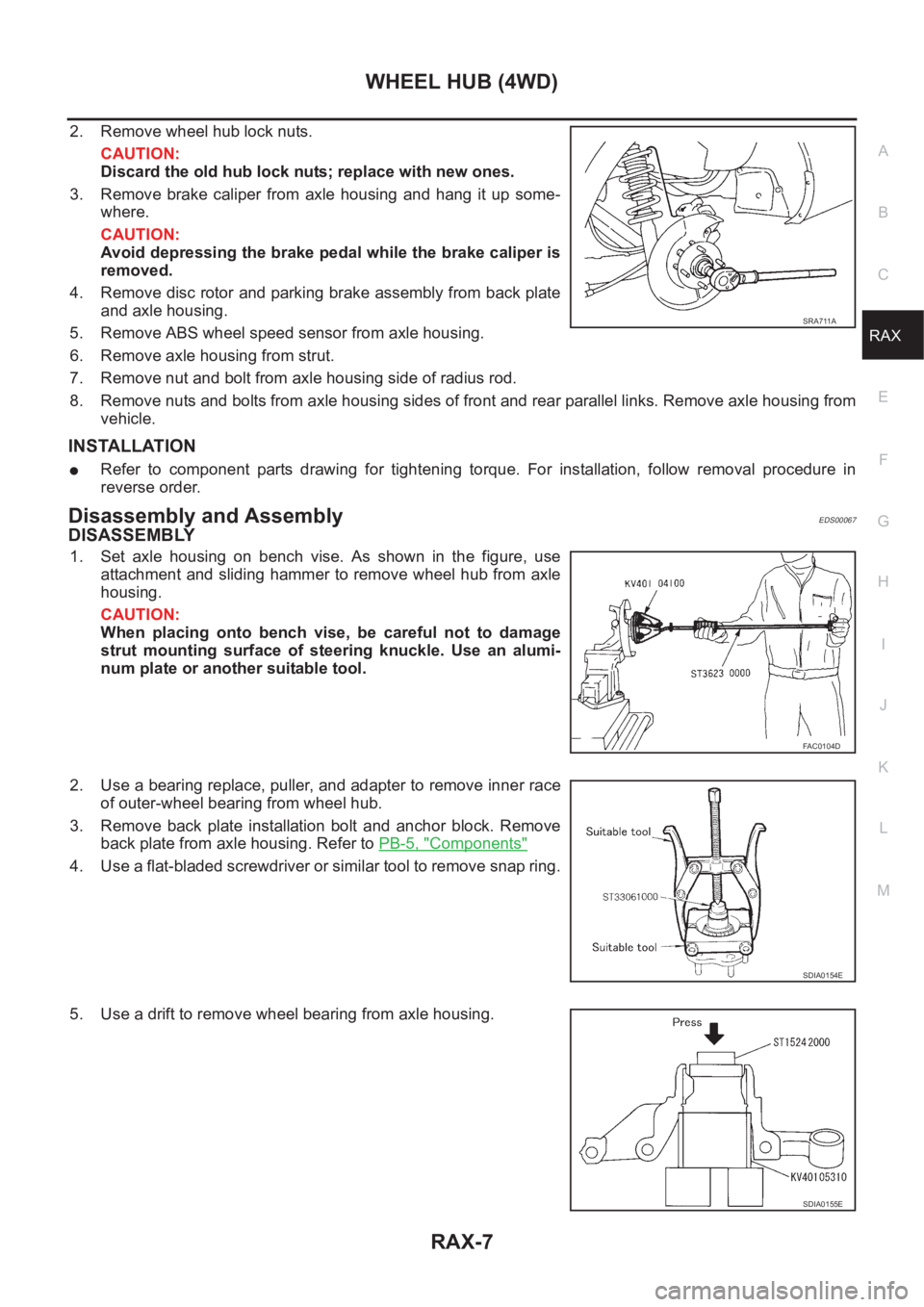
2. Remove wheel hub lock nuts.
CAUTION:
Discard the old hub lock nuts; replace with new ones.
3. Remove brake caliper from axle housing and hang it up some-
where.
CAUTION:
Avoid depressing the brake pedal while the brake caliper is
removed.
4. Remove disc rotor and parking brake assembly from back plate
and axle housing.
5. Remove ABS wheel speed sensor from axle housing.
6. Remove axle housing from strut.
7. Remove nut and bolt from axle housing side of radius rod.
8. Remove nuts and bolts from axle housing sides of front and rear parallel links. Remove axle housing from
vehicle.
INSTALLATION
●Refer to component parts drawing for tightening torque. For installation, follow removal procedure in
reverse order.
Disassembly and AssemblyEDS00067
DISASSEMBLY
1. Set axle housing on bench vise. As shown in the figure, use
attachment and sliding hammer to remove wheel hub from axle
housing.
CAUTION:
When placing onto bench vise, be careful not to damage
strut mounting surface of steering knuckle. Use an alumi-
num plate or another suitable tool.
2. Use a bearing replace, puller, and adapter to remove inner race
of outer-wheel bearing from wheel hub.
3. Remove back plate installation bolt and anchor block. Remove
back plate from axle housing. Refer to PB-5, "
Components"
4. Use a flat-bladed screwdriver or similar tool to remove snap ring.
5. Use a drift to remove wheel bearing from axle housing.
SRA711A
FAC0104D
SDIA0154E
SDIA0155E
Page 3782 of 3833
MA-2
Changing Engine Oil ............................................ ... 32
Changing Oil Filter .................................................. 33
REMOVAL ........................................................... 33
INSTALLATION .................................................... 34
Draining Water ........................................................ 34
CHASSIS AND BODY MAINTENANCE ................... 35
Checking Exhaust System ...................................... 35
Checking Clutch Fluid Level and Leaks ................. 35
Checking Clutch System ........................................ 35
Checking M/T Oil .................................................... 35
Changing M/T Oil .................................................... 35
Checking A/T Fluid ................................................. 36
Changing A/T Fluid ................................................. 36
Checking Transfer Oil ............................................. 37
Changing Transfer Oil .......................................... ... 37
Checking Propeller Shaft ........................................ 37
Checking Differential Gear Oil ................................ 38
Changing Differential Gear Oil ................................ 38
Balancing Wheels ................................................... 38
Rotation .................................................................. 38
Checking Brake Fluid Level and Leaks .................. 39
Checking Brake Lines and Cables ......................... 39
Changing Brake Fluid ............................................. 39
Checking Disc Brake .............................................. 39
ROTOR ................................................................ 39
CALIPER ............................................................. 40PAD ...................................................................... 40
Checking Steering Gear and Linkage ..................... 40
STEERING GEAR ............................................... 40
STEERING LINKAGE .......................................... 40
Checking Power Steering Fluid and Lines .............. 40
Axle and Suspension Parts ..................................... 41
Drive Shaft .............................................................. 41
Lubricating Locks, Hinges and Hood Latches ......... 41
Checking Seat Belts, Buckles, Retractors, Anchors
and Adjusters .......................................................... 42
Checking Body Corrosion ....................................... 42
HEMMED PANELS .............................................. 42
PANEL JOINT ...................................................... 42
PANEL EDGE ...................................................... 42
PARTS CONTACT ............................................... 42
PROTECTORS .................................................... 42
ANTI-CORROSION MATERIALS ........................ 42
DRAIN HOLES ..................................................... 42
SERVICE DATA AND SPECIFICATIONS (SDS) ...... 43
Standard and Limit .................................................. 43
BELT DEFLECTION AND TENSION ................... 43
RADIATOR ........................................................... 43
ENGINE COOLANT CAPACITY .......................... 43
ENGINE OIL CAPACITY ...................................... 43
SPARK PLUG ...................................................... 43
Page 3788 of 3833

MA-8
PERIODIC MAINTENANCE
Abbreviations: I = Inspect and correct or replace as necessary,R = Replace, L = Lubricate.
NOTE:
●(1) Inspect once per year.
● Maintenance items with “ ” should be performed more frequently according to “Maintenance Under Severe Driving
Conditions”.
ENGINE AND EMISSION CONTROL MAINTENANCE (YD22DDTI DIESEL ENGINE)
(Annual Mileage <30,000 Km/year)
Abbreviations: I = Inspect and correct or replace as necessary,R = Replace, D = Check filter and drain water MAINTENANCE OPERATIONMAINTENANCE INTERVAL
Reference
page Perform either at number of kilometers
(miles) or months, whichever comes
first.km x 1,000
(Miles x 1,000)
Months15
(9)
1230
(18)
2445
(27)
3660
(36)
4875
(45)
6090
(54)
72105
(63)
84120
(72)
96
Underhood and under vehicle
Headlamp aiming I I I I I I I ILT- 6
Brake & clutch, systems and fluid (For
level & leaks)IIIIIIIIMA-35,MA-
39
Brake fluidRRRRMA-39
Brake booster vacuum hoses, connec-
tions & check valveIIIIBR-19
Power steering fluid & lines (For level
& leaks)IIIIIIIIMA-40
Manual transaxle gear oil (For level &
leaks)IIIIIIIIMA-35
Automatic transaxle fluid (For level &
leaks)IIIIIIIIMA-36
Transfer gear oil (For level & leaks) I I I I I I I IMA-37
Differential gear oil (For level & leaks
or replace)IIIRIIIRMA-38,MA-
38
Steering gear & linkage, axle & sus-
pension parts, propeller shaft, front
drive shafts & exhaust systemIIIIIIIIMA-40,MA-
41 ,MA-37
,MA-41,
"Drive
Shaft"
Wheel alignment (If necessary, rotate
& balance wheels)IIIIIIIIFSU-6,MA-
38
Brake pads, rotors & other brake com-
ponentsIIIIIIIIMA-40,MA-
40 ,MA-39
Foot brake, parking brake & clutch (For
free play, stroke & operation)IIIIIIIIBR-6PB-3,
CL-5
Ventilation air filterRRRRAT C - 1 2 1
Body corrosion See NOTE (1)MA-42
MAINTENANCE OPERATIONMAINTENANCE INTERVAL
Refer-
ence page Perform either at number of kilometers (miles) or
months, whichever comes first.km x 1,000
(Miles x
1,000)
Months20
(12)
1240
(24)
2460
(36)
3680
(48)
48100
(60)
60120
(72)
72
Engine compartment and under vehicle
Intake & exhaust valve clearanceSee NOTE
(1)EM-163
Drive belts I I I I I IMA-26
Engine oil (Use API CD, CE, CF, CF-4 oil.)See NOTE
(2)RRRRRRMA-32