NISSAN X-TRAIL 2001 Service Repair Manual
Manufacturer: NISSAN, Model Year: 2001, Model line: X-TRAIL, Model: NISSAN X-TRAIL 2001Pages: 3833, PDF Size: 39.49 MB
Page 3051 of 3833
COLLISION DIAGNOSIS
SRS-49
C
D
E
F
G
I
J
K
L
MA
B
SRS
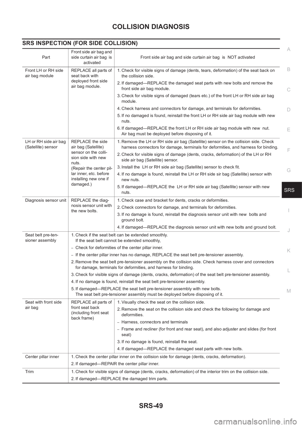
SRS INSPECTION (FOR SIDE COLLISION)
PartFront side air bag and
side curtain air bag is
activatedFront side air bag and side curtain air bag is NOT activated
Front LH or RH side
air bag moduleREPLACE all parts of
seat back with
deployed front side
air bag module.1. Check for visible signs of damage (dents, tears, deformation) of the seat back on
the collision side.
2. If damaged—REPLACE the damaged seat parts with new bolts and remove the
front side air bag module.
3. Check for visible signs of damaged (tears etc.) of the front LH or RH side air bag
module.
4. Check harness and connectors for damage, and terminals for deformities.
5. If no damaged is found, reinstall the front LH or RH side air bag module with new
nuts.
6. If damaged—REPLACE the front LH or RH side air bag module with new nut.
Air bag must be deployed before disposing of it.
LH or RH side air bag
(Satellite) sensor REPLACE the side
air bag (Satellite)
sensor on the colli-
sion side with new
nuts.
(Repair the center pil-
lar inner, etc. before
installing new one if
damaged.)1. Remove the LH or RH side air bag (Satellite) sensor on the collision side. Check
harness connectors for damage, terminals for deformities, and harness for binding.
2. Check for visible signs of damage (dents, cracks, deformation) of the LH or RH
side air bag (Satellite) sensor.
3. Install the LH or RH side air bag (Satellite) sensor to check fit.
4. If no damage is found, reinstall the LH or RH side sir bag (Satellite) sensor with
new nuts.
5. If damaged—REPLACE the LH or RH side air bag (Satellite) sensor with new
nuts.
Diagnosis sensor unit REPLACE the diag-
nosis sensor unit with
the new bolts.1. Check case and bracket for dents, cracks or deformities.
2. Check connectors for damage, and terminals for deformities.
3. If no damage is found, reinstall the diagnosis sensor unit with new bolts and
ground bolt.
4. If damaged—REPLACE the diagnosis sensor unit with new bolts and ground bolt.
Seat belt pre-ten-
sioner assembly1. Check if the seat belt can be extended smoothly.
If the seat belt cannot be extended smoothly,
–Check for deformities of the center pillar inner.
–If the center pillar inner has no damage, REPLACE the seat belt pre-tensioner assembly.
2. Remove the seat belt pre-tensioner assembly on the collision side. Check harness cover and connectors
for damage, terminals for deformities, and harness for binding.
3. Check for visible signs of damage (dents, cracks, deformation) of the seat belt pre-tensioner assembly.
4. If no damage is found, reinstall the seat belt pre-tensioner assembly.
5. If damaged—REPLACE the seat belt pre-tensioner assembly with new bolts.
The seat belt pre-tensioner assembly must be deployed before disposing of it.
Seat with front side
air bagREPLACE all parts of
front seat back
(including front seat
back frame)1. Visually check the seat on the collision side.
2. Remove the seat on the collision side and check the following for damage and
deformities.
–Harness, connectors and terminals
–Frame and recliner (for front and rear seat), and also adjuster and slides (for front
seat)
3. If no damage is found, reinstall the seat.
4. If damaged—REPLACE the damaged seat parts with new bolts.
Center pillar inner 1. Check the center pillar inner on the collision side for damage (dents, cracks, deformation).
2. If damaged—REPAIR the center pillar inner.
Trim 1. Check for visible signs of damage (dents, cracks, deformation) of the interior trim on the collision side.
2. If damaged—REPLACE the damaged trim parts.
Page 3052 of 3833

SRS-50
COLLISION DIAGNOSIS
Page 3053 of 3833
BL-1
BODY, LOCK & SECURITY SYSTEM
I BODY
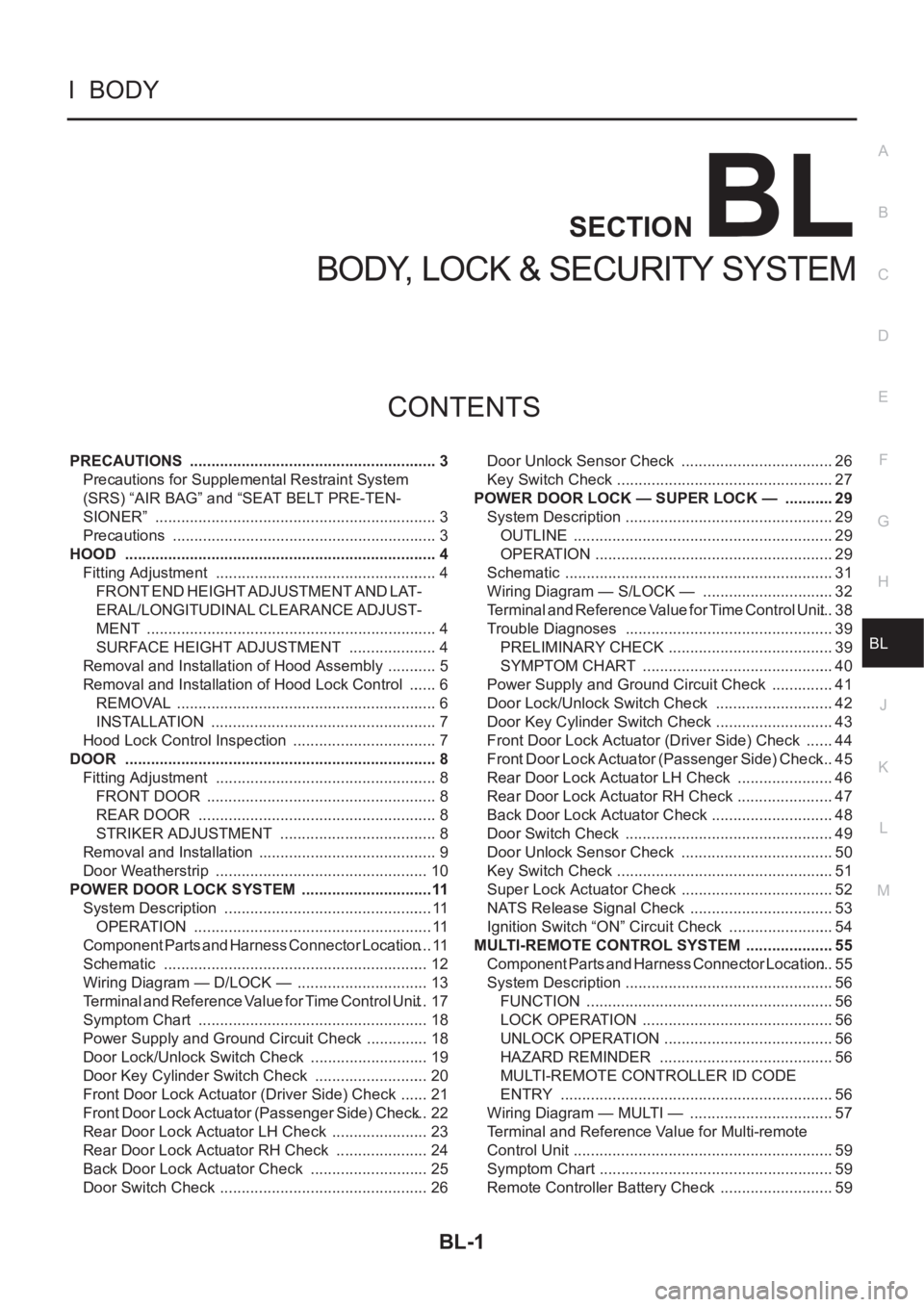
CONTENTS
C
D
E
F
G
H
J
K
L
M
SECTION
A
B
BL
BODY, LOCK & SECURITY SYSTEM
PRECAUTIONS .......................................................... 3
Precautions for Supplemental Restraint System
(SRS) “AIR BAG” and “SEAT BELT PRE-TEN-
SIONER” .................................................................. 3
Precautions .............................................................. 3
HOOD ......................................................................... 4
Fitting Adjustment .................................................... 4
FRONT END HEIGHT ADJUSTMENT AND LAT-
ERAL/LONGITUDINAL CLEARANCE ADJUST-
MENT .................................................................... 4
SURFACE HEIGHT ADJUSTMENT ..................... 4
Removal and Installation of Hood Assembly ............ 5
Removal and Installation of Hood Lock Control ....... 6
REMOVAL ............................................................. 6
INSTALLATION ..................................................... 7
Hood Lock Control Inspection .................................. 7
DOOR ......................................................................... 8
Fitting Adjustment .................................................... 8
FRONT DOOR ...................................................... 8
REAR DOOR ........................................................ 8
STRIKER ADJUSTMENT ..................................... 8
Removal and Installation .......................................... 9
Door Weatherstrip .................................................. 10
POWER DOOR LOCK SYSTEM ...............................11
System Description ................................................. 11
OPERATION ........................................................ 11
Component Parts and Harness Connector Location .... 11
Schematic .............................................................. 12
Wiring Diagram — D/LOCK — ............................... 13
Terminal and Reference Value for Time Control Unit ... 17
Symptom Chart ...................................................... 18
Power Supply and Ground Circuit Check ............... 18
Door Lock/Unlock Switch Check ............................ 19
Door Key Cylinder Switch Check ........................... 20
Front Door Lock Actuator (Driver Side) Check ....... 21
Front Door Lock Actuator (Passenger Side) Check ... 22
Rear Door Lock Actuator LH Check ....................... 23
Rear Door Lock Actuator RH Check ...................... 24
Back Door Lock Actuator Check ............................ 25
Door Switch Check ................................................. 26Door Unlock Sensor Check .................................... 26
Key Switch Check ................................................... 27
POWER DOOR LOCK — SUPER LOCK — ............ 29
System Description ................................................. 29
OUTLINE ............................................................. 29
OPERATION .....................................................
... 29
Schematic ............................................................... 31
Wiring Diagram — S/LOCK — ............................... 32
Terminal and Reference Value for Time Control Unit ... 38
Trouble Diagnoses ................................................. 39
PRELIMINARY CHECK ....................................... 39
SYMPTOM CHART ............................................. 40
Power Supply and Ground Circuit Check ............... 41
Door Lock/Unlock Switch Check ............................ 42
Door Key Cylinder Switch Check ............................ 43
Front Door Lock Actuator (Driver Side) Check ....... 44
Front Door Lock Actuator (Passenger Side) Check ... 45
Rear Door Lock Actuator LH Check ....................... 46
Rear Door Lock Actuator RH Check ....................... 47
Back Door Lock Actuator Check ............................. 48
Door Switch Check ................................................. 49
Door Unlock Sensor Check .................................... 50
Key Switch Check ................................................... 51
Super Lock Actuator Check .................................... 52
NATS Release Signal Check .................................. 53
Ignition Switch “ON” Circuit Check ......................... 54
MULTI-REMOTE CONTROL SYSTEM ..................... 55
Component Parts and Harness Connector Location ... 55
System Description ................................................. 56
FUNCTION .......................................................... 56
LOCK OPERATION ............................................. 56
UNLOCK OPERATION ........................................ 56
HAZARD REMINDER ......................................... 56
MULTI-REMOTE CONTROLLER ID CODE
ENTRY ................................................................ 56
Wiring Diagram — MULTI — .................................. 57
Terminal and Reference Value for Multi-remote
Control Unit ............................................................. 59
Symptom Chart ....................................................... 59
Remote Controller Battery Check ........................... 59
Page 3054 of 3833
BL-2
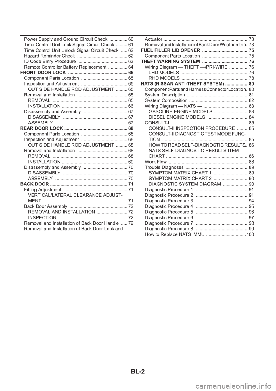
Power Supply and Ground Circuit Check ............... 60
Time Control Unit Lock Signal Circuit Check .......... 61
Time Control Unit Unlock Signal Circuit Check ...... 62
Hazard Reminder Check ........................................ 62
ID Code Entry Procedure ....................................... 63
Remote Controller Battery Replacement ................ 64
FRONT DOOR LOCK ............................................... 65
Component Parts Location ..................................... 65
Inspection and Adjustment ..................................... 65
OUT SIDE HANDLE ROD ADJUSTMENT .......... 65
Removal and Installation ........................................ 65
REMOVAL ........................................................... 65
INSTALLATION .................................................... 66
Disassembly and Assembly .................................... 67
DISASSEMBLY ................................................... 67
ASSEMBLY ......................................................... 67
REAR DOOR LOCK .................................................. 68
Component Parts Location ..................................... 68
Inspection and Adjustment ..................................... 68
OUT SIDE HANDLE ROD ADJUSTMENT .......... 68
Removal and Installation ........................................ 68
REMOVAL ........................................................... 68
INSTALLATION .................................................... 69
Disassembly and Assembly .................................... 70
DISASSEMBLY ................................................... 70
ASSEMBLY ......................................................... 70
BACK DOOR ............................................................. 71
Fitting Adjustment ................................................... 71
VERTICAL/LATERAL CLEARANCE ADJUST-
MENT .................................................................. 71
Back Door Assembly .............................................. 72
REMOVAL AND INSTALLATION ......................... 72
INSPECTION ....................................................... 72
Removal and Installation of Back Door Handle ...... 72
Removal and Installation of Back Door Lock and Actuator ................................................................... 73
Removal and Installation of Back Door Weatherstrip ... 73
FUEL FILLER LID OPENER ..................................... 75
Component Parts Location ..................................... 75
THEFT WARNING SYSTEM ..................................... 76
Wiring Diagram — THEFT —/PRI-WIRE ................ 76
LHD MODELS ...................................................... 76
RHD MODELS ..................................................... 78
NATS (NISSAN ANTI-THEFT SYSTEM) ................... 80
Component Parts and Harness Connector Location ... 80
System Description ................................................. 81
System Composition ............................................... 82
Wiring Diagram — NATS — .................................... 83
GASOLINE ENGINE MODELS ............................ 83
DIESEL ENGINE MODELS ................................. 84
CONSULT-II ............................................................ 85
CONSULT-II INSPECTION PROCEDURE .......... 85
CONSULT-II DIAGNOSTIC TEST MODE FUNC-
TION .................................................................... 85
HOW TO READ SELF-DIAGNOSTIC RESULTS ... 86
NATS SELF-DIAGNOSTIC RESULTS ITEM
CHART ................................................................. 86
Work Flow ............................................................... 88
Trouble Diagnoses .................................................. 89
SYMPTOM MATRIX CHART 1 ............................ 89
SYMPTOM MATRIX CHART 2 ............................ 90
DIAGNOSTIC SYSTEM DIAGRAM ..................... 90
Diagnostic Procedure 1 ........................................... 91
Diagnostic Procedure 2 ........................................... 91
Diagnostic Procedure 3 ........................................... 94
Diagnostic Procedure 4 ........................................... 95
Diagnostic Procedure 5 ........................................... 96
Diagnostic Procedure 6 ........................................... 97
Diagnostic Procedure 7 ........................................... 98
Diagnostic Procedure 8 ........................................... 99
How to Replace NATS IMMU ................................100
Page 3055 of 3833
PRECAUTIONS
BL-3
C
D
E
F
G
H
J
K
L
MA
B
BL
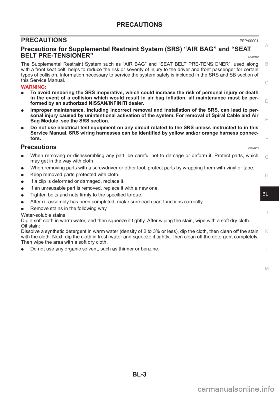
PRECAUTIONSPFP:00001
Precautions for Supplemental Restraint System (SRS) “AIR BAG” and “SEAT
BELT PRE-TENSIONER”
EIS00452
The Supplemental Restraint System such as “AIR BAG” and “SEAT BELT PRE-TENSIONER”, used along
with a front seat belt, helps to reduce the risk or severity of injury to the driver and front passenger for certain
types of collision. Information necessary to service the system safely is included in the SRS and SB section of
this Service Manual.
WARNING:
●To avoid rendering the SRS inoperative, which could increase the risk of personal injury or death
in the event of a collision which would result in air bag inflation, all maintenance must be per-
formed by an authorized NISSAN/INFINITI dealer.
●Improper maintenance, including incorrect removal and installation of the SRS, can lead to per-
sonal injury caused by unintentional activation of the system. For removal of Spiral Cable and Air
Bag Module, see the SRS section.
●Do not use electrical test equipment on any circuit related to the SRS unless instructed to in this
Service Manual. SRS wiring harnesses can be identified by yellow and/or orange harness connec-
tors.
Precautions EIS00453
●When removing or disassembling any part, be careful not to damage or deform it. Protect parts, which
may get in the way with cloth.
●When removing parts with a screwdriver or other tool, protect parts by wrapping them with vinyl or tape.
●Keep removed parts protected with cloth.
●If a clip is deformed or damaged, replace it.
●If an unreusable part is removed, replace it with a new one.
●Tighten bolts and nuts firmly to the specified torque.
●After re-assembly has been completed, make sure each part functions correctly.
●Remove stains in the following way.
Water-soluble stains:
Dip a soft cloth in warm water, and then squeeze it tightly. After wiping the stain, wipe with a soft dry cloth.
Oil stain:
Dissolve a synthetic detergent in warm water (density of 2 to 3% or less), dip the cloth, then clean off the stain
with the cloth. Next, dip the cloth in fresh water and squeeze it tightly. Then clean off the detergent completely.
Then wipe the area with a soft dry cloth.
●Do not use any organic solvent, such as thinner or benzine.
Page 3056 of 3833
BL-4
HOOD
HOOD
PFP:65100
Fitting AdjustmentEIS000KF
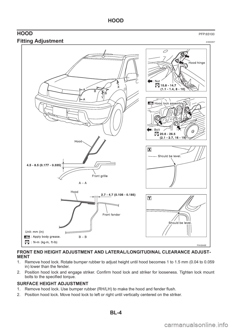
FRONT END HEIGHT ADJUSTMENT AND LATERAL/LONGITUDINAL CLEARANCE ADJUST-
MENT
1. Remove hood lock. Rotate bumper rubber to adjust height until hood becomes 1 to 1.5 mm (0.04 to 0.059
in) lower than the fender.
2. Position hood lock and engage striker. Confirm hood lock and striker for looseness. Tighten lock mount
bolts to the specified torque.
SURFACE HEIGHT ADJUSTMENT
1. Remove hood lock. Use bumper rubber (RH/LH) to make the hood and fender flush.
2. Position hood lock. Move hood lock to left or right until vertically centered on the striker.
PIIA3649E
Page 3057 of 3833
HOOD
BL-5
C
D
E
F
G
H
J
K
L
MA
B
BL
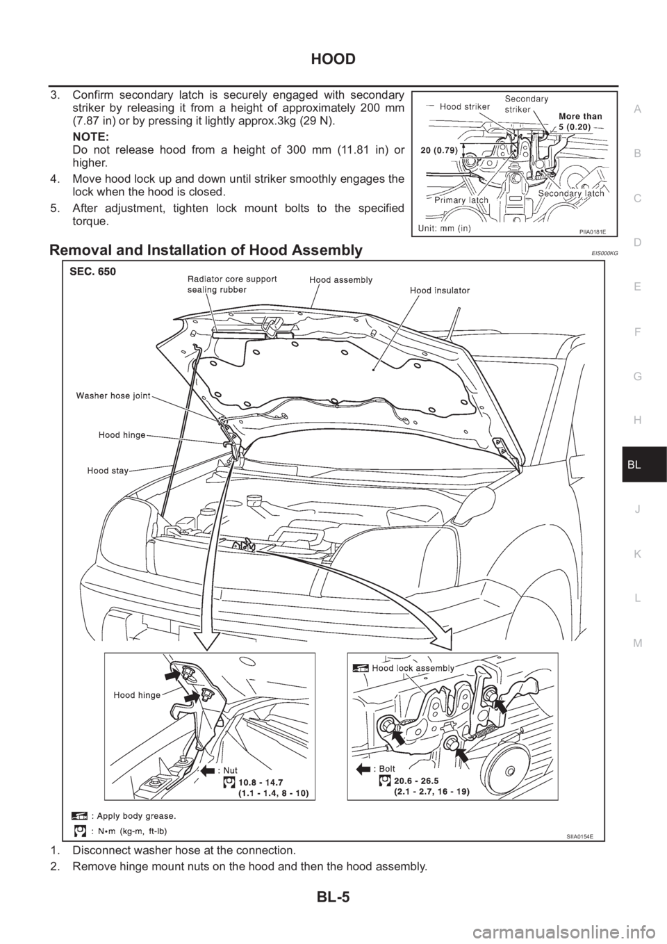
3. Confirm secondary latch is securely engaged with secondary
striker by releasing it from a height of approximately 200 mm
(7.87 in) or by pressing it lightly approx.3kg (29 N).
NOTE:
Do not release hood from a height of 300 mm (11.81 in) or
higher.
4. Move hood lock up and down until striker smoothly engages the
lock when the hood is closed.
5. After adjustment, tighten lock mount bolts to the specified
torque.
Removal and Installation of Hood AssemblyEIS000KG
1. Disconnect washer hose at the connection.
2. Remove hinge mount nuts on the hood and then the hood assembly.
PIIA0181E
SIIA0154E
Page 3058 of 3833
BL-6
HOOD
Install in the reverse order of removal.
Removal and Installation of Hood Lock ControlEIS000KH
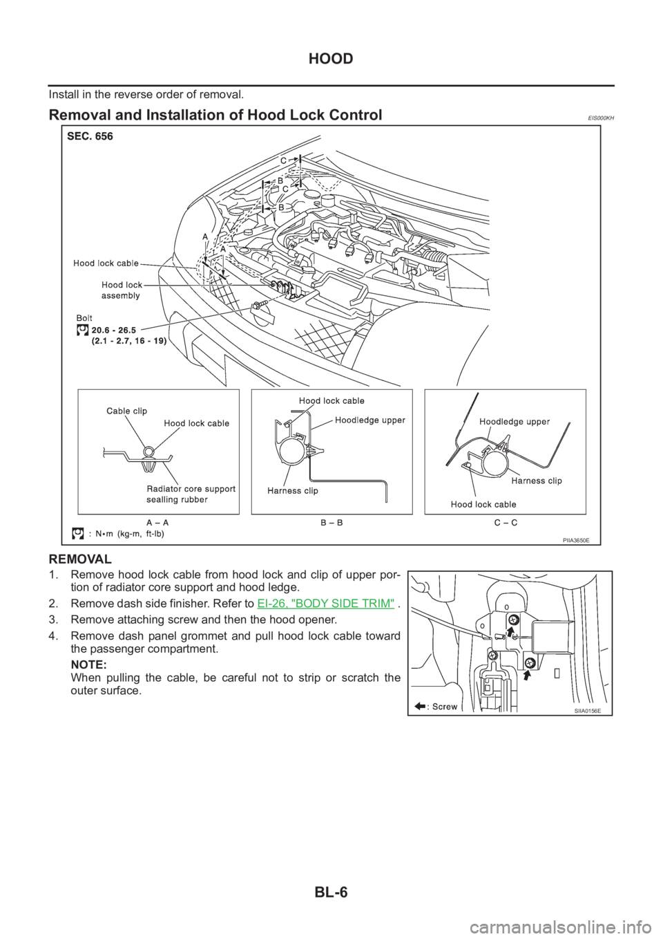
REMOVAL
1. Remove hood lock cable from hood lock and clip of upper por-
tion of radiator core support and hood ledge.
2. Remove dash side finisher. Refer to EI-26, "
BODY SIDE TRIM" .
3. Remove attaching screw and then the hood opener.
4. Remove dash panel grommet and pull hood lock cable toward
the passenger compartment.
NOTE:
When pulling the cable, be careful not to strip or scratch the
outer surface.
PIIA3650E
SIIA0156E
Page 3059 of 3833
HOOD
BL-7
C
D
E
F
G
H
J
K
L
MA
B
BL
INSTALLATION
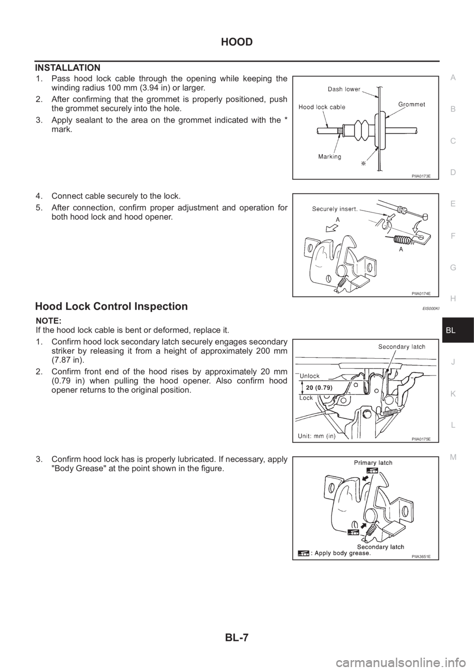
1. Pass hood lock cable through the opening while keeping the
winding radius 100 mm (3.94 in) or larger.
2. After confirming that the grommet is properly positioned, push
the grommet securely into the hole.
3. Apply sealant to the area on the grommet indicated with the *
mark.
4. Connect cable securely to the lock.
5. After connection, confirm proper adjustment and operation for
both hood lock and hood opener.
Hood Lock Control InspectionEIS000KI
NOTE:
If the hood lock cable is bent or deformed, replace it.
1. Confirm hood lock secondary latch securely engages secondary
striker by releasing it from a height of approximately 200 mm
(7.87 in).
2. Confirm front end of the hood rises by approximately 20 mm
(0.79 in) when pulling the hood opener. Also confirm hood
opener returns to the original position.
3. Confirm hood lock has is properly lubricated. If necessary, apply
"Body Grease" at the point shown in the figure.
PIIA0173E
PIIA0174E
PIIA0175E
PIIA3651E
Page 3060 of 3833
BL-8
DOOR
DOOR
PFP:80100
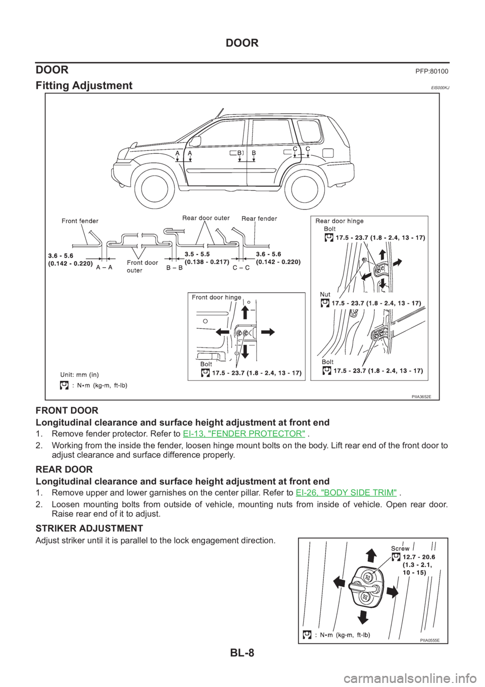
Fitting AdjustmentEIS000KJ
FRONT DOOR
Longitudinal clearance and surface height adjustment at front end
1. Remove fender protector. Refer to EI-13, "FENDER PROTECTOR" .
2. Working from the inside the fender, loosen hinge mount bolts on the body. Lift rear end of the front door to
adjust clearance and surface difference properly.
REAR DOOR
Longitudinal clearance and surface height adjustment at front end
1. Remove upper and lower garnishes on the center pillar. Refer to EI-26, "BODY SIDE TRIM" .
2. Loosen mounting bolts from outside of vehicle, mounting nuts from inside of vehicle. Open rear door.
Raise rear end of it to adjust.
STRIKER ADJUSTMENT
Adjust striker until it is parallel to the lock engagement direction.
PIIA3652E
PIIA0555E