NISSAN X-TRAIL 2001 Service Repair Manual
Manufacturer: NISSAN, Model Year: 2001, Model line: X-TRAIL, Model: NISSAN X-TRAIL 2001Pages: 3833, PDF Size: 39.49 MB
Page 3151 of 3833
NATS (NISSAN ANTI-THEFT SYSTEM)
BL-99
C
D
E
F
G
H
J
K
L
MA
B
BL
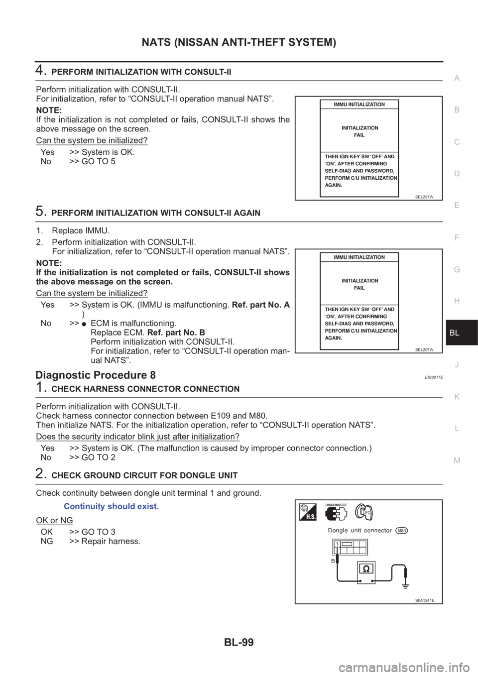
4.PERFORM INITIALIZATION WITH CONSULT-II
Perform initialization with CONSULT-II.
For initialization, refer to “CONSULT-II operation manual NATS”.
NOTE:
If the initialization is not completed or fails, CONSULT-II shows the
above message on the screen.
Can the system be initialized?
Yes >> System is OK.
No >> GO TO 5
5.PERFORM INITIALIZATION WITH CONSULT-II AGAIN
1. Replace IMMU.
2. Perform initialization with CONSULT-II.
For initialization, refer to “CONSULT-II operation manual NATS”.
NOTE:
If the initialization is not completed or fails, CONSULT-II shows
the above message on the screen.
Can the system be initialized?
Yes >> System is OK. (IMMU is malfunctioning. Ref. part No. A
)
No >>
●ECM is malfunctioning.
Replace ECM. Ref. part No. B
Perform initialization with CONSULT-II.
For initialization, refer to “CONSULT-II operation man-
ual NATS”.
Diagnostic Procedure 8EIS001TE
1.CHECK HARNESS CONNECTOR CONNECTION
Perform initialization with CONSULT-II.
Check harness connector connection between E109 and M80.
Then initialize NATS. For the initialization operation, refer to “CONSULT-II operation NATS”.
Does the security indicator blink just after initialization?
Yes >> System is OK. (The malfunction is caused by improper connector connection.)
No >> GO TO 2
2.CHECK GROUND CIRCUIT FOR DONGLE UNIT
Check continuity between dongle unit terminal 1 and ground.
OK or NG
OK >> GO TO 3
NG >> Repair harness.
SEL297W
SEL297W
Continuity should exist.
SIIA1241E
Page 3152 of 3833
BL-100
NATS (NISSAN ANTI-THEFT SYSTEM)
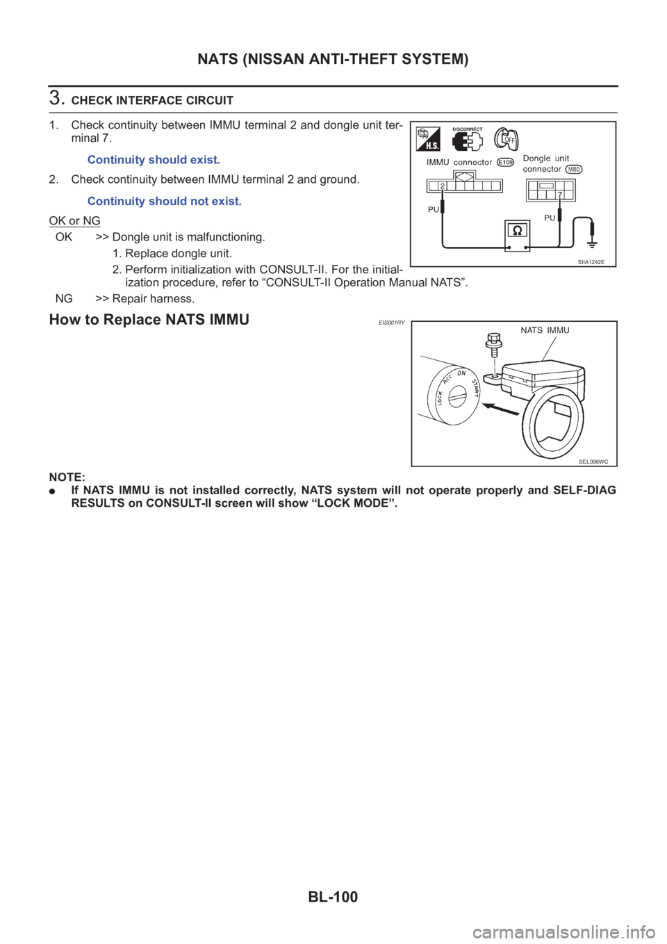
3. CHECK INTERFACE CIRCUIT
1. Check continuity between IMMU terminal 2 and dongle unit ter-
minal 7.
2. Check continuity between IMMU terminal 2 and ground.
OK or NG
OK >> Dongle unit is malfunctioning.
1. Replace dongle unit.
2. Perform initialization with CONSULT-II. For the initial-
ization procedure, refer to “CONSULT-II Operation Manual NATS”.
NG >> Repair harness.
How to Replace NATS IMMUEIS001RY
NOTE:
●If NATS IMMU is not installed correctly, NATS system will not operate properly and SELF-DIAG
RESULTS on CONSULT-II screen will show “LOCK MODE”.Continuity should exist.
Continuity should not exist.
SIIA1242E
SEL096WC
Page 3153 of 3833
GW-1
GLASSES, WINDOW SYSTEM & MIRRORS
I BODY
CONTENTS
C
D
E
F
G
H
J
K
L
M
SECTION
A
B
GW
GLASSES, WINDOW SYSTEM & MIRRORS
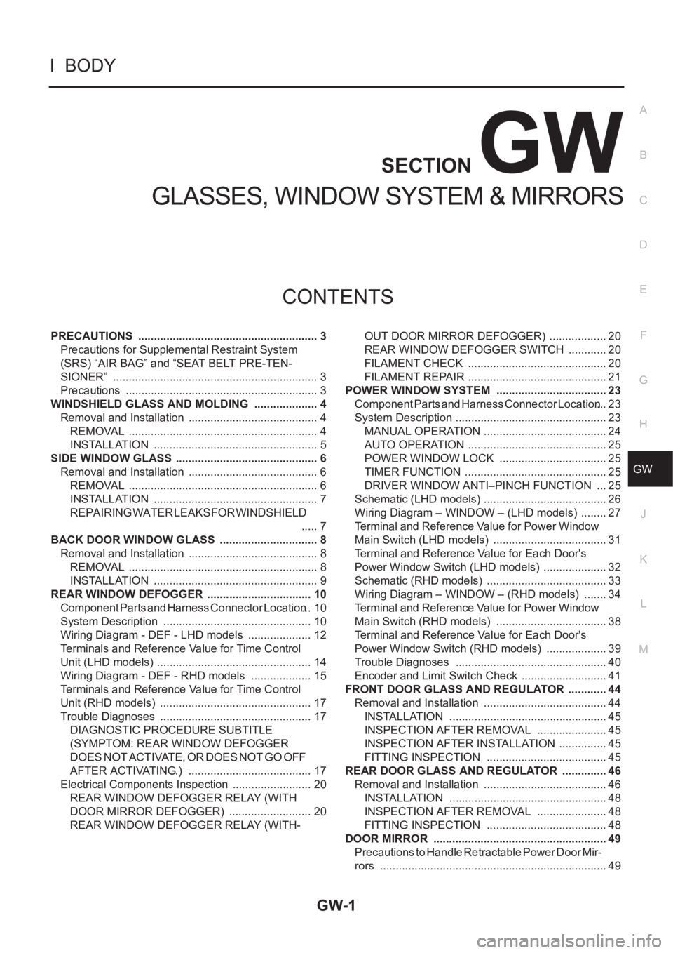
PRECAUTIONS .......................................................... 3
Precautions for Supplemental Restraint System
(SRS) “AIR BAG” and “SEAT BELT PRE-TEN-
SIONER” .................................................................. 3
Precautions .............................................................. 3
WINDSHIELD GLASS AND MOLDING ..................... 4
Removal and Installation .......................................... 4
REMOVAL ............................................................. 4
INSTALLATION ..................................................... 5
SIDE WINDOW GLASS .............................................. 6
Removal and Installation .......................................... 6
REMOVAL ............................................................. 6
INSTALLATION ..................................................... 7
REPAIRING WATER LEAKS FOR WINDSHIELD
..... 7
BACK DOOR WINDOW GLASS ................................ 8
Removal and Installation .......................................... 8
REMOVAL ............................................................. 8
INSTALLATION ..................................................... 9
REAR WINDOW DEFOGGER .................................. 10
Component Parts and Harness Connector Location ... 10
System Description ................................................ 10
Wiring Diagram - DEF - LHD models ..................... 12
Terminals and Reference Value for Time Control
Unit (LHD models) .................................................. 14
Wiring Diagram - DEF - RHD models .................... 15
Terminals and Reference Value for Time Control
Unit (RHD models) .............................................. ... 17
Trouble Diagnoses ................................................. 17
DIAGNOSTIC PROCEDURE SUBTITLE
(SYMPTOM: REAR WINDOW DEFOGGER
DOES NOT ACTIVATE, OR DOES NOT GO OFF
AFTER ACTIVATING.) ........................................ 17
Electrical Components Inspection .......................... 20
REAR WINDOW DEFOGGER RELAY (WITH
DOOR MIRROR DEFOGGER) ........................... 20
REAR WINDOW DEFOGGER RELAY (WITH-OUT DOOR MIRROR DEFOGGER) ................... 20
REAR WINDOW DEFOGGER SWITCH ............. 20
FILAMENT CHECK ............................................. 20
FILAMENT REPAIR ............................................. 21
POWER WINDOW SYSTEM .................................... 23
Component Parts and Harness Connector Location ... 23
System Description ................................................. 23
MANUAL OPERATION ........................................ 24
AUTO OPERATION ............................................. 25
POWER WINDOW LOCK ................................... 25
TIMER FUNCTION .............................................. 25
DRIVER WINDOW ANTI–PINCH FUNCTION .... 25
Schematic (LHD models) ........................................ 26
Wiring Diagram – WINDOW – (LHD models) ......... 27
Terminal and Reference Value for Power Window
Main Switch (LHD models) ..................................... 31
Terminal and Reference Value for Each Door's
Power Window Switch (LHD models) ..................... 32
Schematic (RHD models) ....................................... 33
Wiring Diagram – WINDOW – (RHD models) ........ 34
Terminal and Reference Value for Power Window
Main Switch (RHD models) .................................... 38
Terminal and Reference Value for Each Door's
Power Window Switch (RHD models) .................... 39
Trouble Diagnoses ................................................. 40
Encoder and Limit Switch Check ............................ 41
FRONT DOOR GLASS AND REGULATOR ............. 44
Removal and Installation ........................................ 44
INSTALLATION ................................................... 45
INSPECTION AFTER REMOVAL ....................... 45
INSPECTION AFTER INSTALLATION ................ 45
FITTING INSPECTION ....................................... 45
REAR DOOR GLASS AND REGULATOR ............... 46
Removal and Installation ........................................ 46
INSTALLATION ................................................... 48
INSPECTION AFTER REMOVAL ....................... 48
FITTING INSPECTION ....................................... 48
DOOR MIRROR ........................................................ 49
Precautions to Handle Retractable Power Door Mir-
rors ......................................................................... 49
Page 3154 of 3833
GW-2
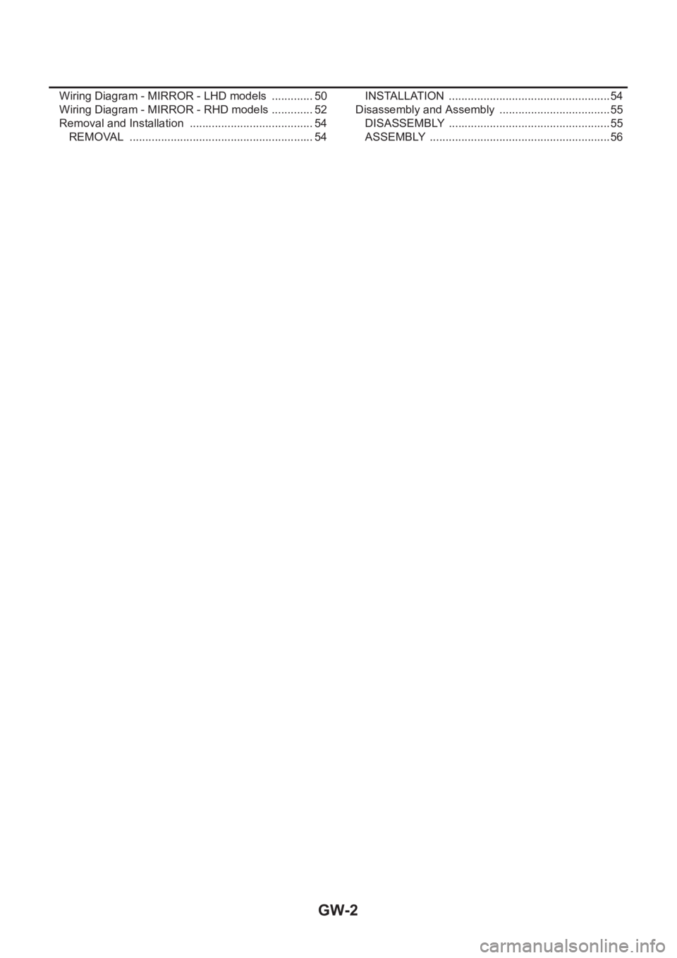
Wiring Diagram - MIRROR - LHD models .............. 50
Wiring Diagram - MIRROR - RHD models .............. 52
Removal and Installation ........................................ 54
REMOVAL ........................................................... 54INSTALLATION .................................................... 54
Disassembly and Assembly .................................... 55
DISASSEMBLY .................................................... 55
ASSEMBLY .......................................................... 56
Page 3155 of 3833
PRECAUTIONS
GW-3
C
D
E
F
G
H
J
K
L
MA
B
GW
PRECAUTIONSPFP:00001
Precautions for Supplemental Restraint System (SRS) “AIR BAG” and “SEAT
BELT PRE-TENSIONER”
EIS0045G
The Supplemental Restraint System such as “AIR BAG” and “SEAT BELT PRE-TENSIONER”, used along
with a front seat belt, helps to reduce the risk or severity of injury to the driver and front passenger for certain
types of collision. Information necessary to service the system safely is included in the SRS and SB section of
this Service Manual.
WARNING:
●To avoid rendering the SRS inoperative, which could increase the risk of personal injury or death
in the event of a collision which would result in air bag inflation, all maintenance must be per-
formed by an authorized NISSAN/INFINITI dealer.
●Improper maintenance, including incorrect removal and installation of the SRS, can lead to per-
sonal injury caused by unintentional activation of the system. For removal of Spiral Cable and Air
Bag Module, see the SRS section.
●Do not use electrical test equipment on any circuit related to the SRS unless instructed to in this
Service Manual. SRS wiring harnesses can be identified by yellow and/or orange harness connec-
tors.
Precautions EIS0045H
●When removing or disassembling any part, be careful not to damage or deform it. Protect parts, which
may get in the way with cloth.
●When removing parts with a screwdriver or other tool, protect parts by wrapping them with vinyl or tape.
●Keep removed parts protected with cloth.
●If a clip is deformed or damaged, replace it.
●If an unreusable part is removed, replace it with a new one.
●Tighten bolts and nuts firmly to the specified torque.
●After re-assembly has been completed, make sure each part functions correctly.
●Remove stains in the following way.
Water-soluble stains:
Dip a soft cloth in warm water, and then squeeze it tightly. After wiping the stain, wipe with a soft dry cloth.
Oil stain:
Dissolve a synthetic detergent in warm water (density of 2 to 3% or less), dip the cloth, then clean off the stain
with the cloth. Next, dip the cloth in fresh water and squeeze it tightly. Then clean off the detergent completely.
Then wipe the area with a soft dry cloth.
●Do not use any organic solvent, such as thinner or benzine.
Page 3156 of 3833
GW-4
WINDSHIELD GLASS AND MOLDING
WINDSHIELD GLASS AND MOLDING
PFP:72700
Removal and InstallationEIS0045I
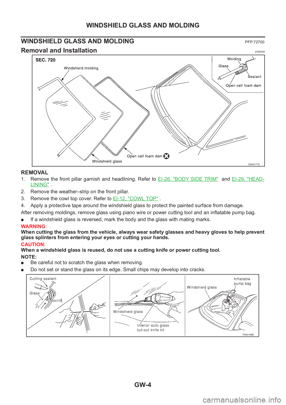
REMOVAL
1. Remove the front pillar garnish and headlining. Refer to EI-26, "BODY SIDE TRIM" and EI-29, "HEAD-
LINING" .
2. Remove the weather–strip on the front pillar.
3. Remove the cowl top cover. Refer to EI-12, "
COWL TOP" .
4. Apply a protective tape around the windshield glass to protect the painted surface from damage.
After removing moldings, remove glass using piano wire or power cutting tool and an inflatable pump bag.
●If a windshield glass is reversed, mark the body and the glass with mating marks.
WARNING:
When cutting the glass from the vehicle, always wear safety glasses and heavy gloves to help prevent
glass splinters from entering your eyes or cutting your hands.
CAUTION:
When a windshield glass is reused, do not use a cutting knife or power cutting tool.
NOTE:
●Be careful not to scratch the glass when removing.
●Do not set or stand the glass on its edge. Small chips may develop into cracks.
SIIA0171E
PIIA0186E
Page 3157 of 3833
WINDSHIELD GLASS AND MOLDING
GW-5
C
D
E
F
G
H
J
K
L
MA
B
GW
INSTALLATION
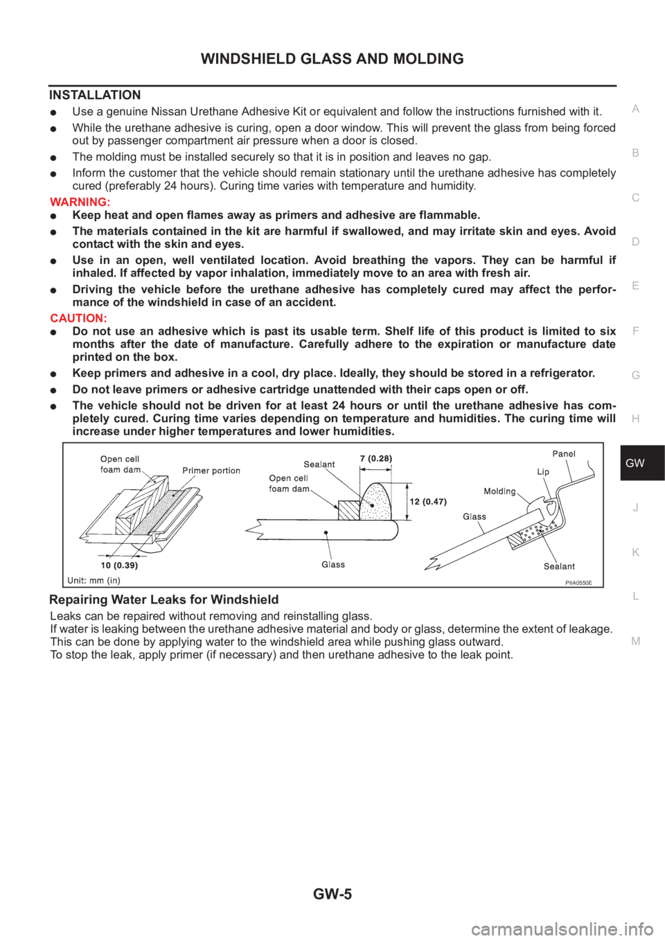
●Use a genuine Nissan Urethane Adhesive Kit or equivalent and follow the instructions furnished with it.
●While the urethane adhesive is curing, open a door window. This will prevent the glass from being forced
out by passenger compartment air pressure when a door is closed.
●The molding must be installed securely so that it is in position and leaves no gap.
●Inform the customer that the vehicle should remain stationary until the urethane adhesive has completely
cured (preferably 24 hours). Curing time varies with temperature and humidity.
WARNING:
●Keep heat and open flames away as primers and adhesive are flammable.
●The materials contained in the kit are harmful if swallowed, and may irritate skin and eyes. Avoid
contact with the skin and eyes.
●Use in an open, well ventilated location. Avoid breathing the vapors. They can be harmful if
inhaled. If affected by vapor inhalation, immediately move to an area with fresh air.
●Driving the vehicle before the urethane adhesive has completely cured may affect the perfor-
mance of the windshield in case of an accident.
CAUTION:
●Do not use an adhesive which is past its usable term. Shelf life of this product is limited to six
months after the date of manufacture. Carefully adhere to the expiration or manufacture date
printed on the box.
●Keep primers and adhesive in a cool, dry place. Ideally, they should be stored in a refrigerator.
●Do not leave primers or adhesive cartridge unattended with their caps open or off.
●The vehicle should not be driven for at least 24 hours or until the urethane adhesive has com-
pletely cured. Curing time varies depending on temperature and humidities. The curing time will
increase under higher temperatures and lower humidities.
Repairing Water Leaks for Windshield
Leaks can be repaired without removing and reinstalling glass.
If water is leaking between the urethane adhesive material and body or glass, determine the extent of leakage.
This can be done by applying water to the windshield area while pushing glass outward.
To stop the leak, apply primer (if necessary) and then urethane adhesive to the leak point.
PIIA0550E
Page 3158 of 3833
GW-6
SIDE WINDOW GLASS
SIDE WINDOW GLASS
PFP:83300
Removal and InstallationEIS0045J
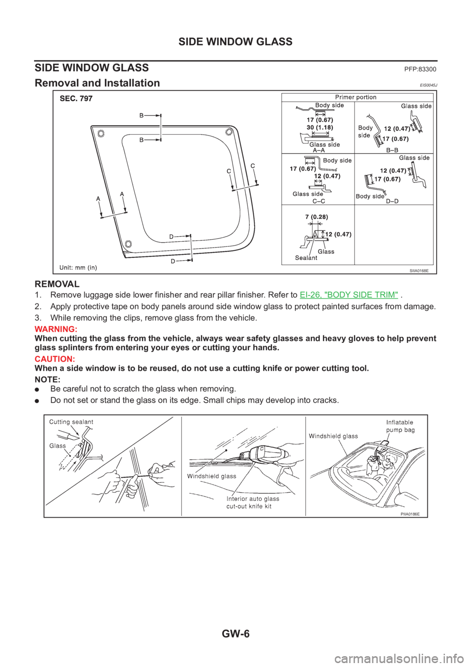
REMOVAL
1. Remove luggage side lower finisher and rear pillar finisher. Refer to EI-26, "BODY SIDE TRIM" .
2. Apply protective tape on body panels around side window glass to protect painted surfaces from damage.
3. While removing the clips, remove glass from the vehicle.
WARNING:
When cutting the glass from the vehicle, always wear safety glasses and heavy gloves to help prevent
glass splinters from entering your eyes or cutting your hands.
CAUTION:
When a side window is to be reused, do not use a cutting knife or power cutting tool.
NOTE:
●Be careful not to scratch the glass when removing.
●Do not set or stand the glass on its edge. Small chips may develop into cracks.
SIIA0168E
PIIA0186E
Page 3159 of 3833
SIDE WINDOW GLASS
GW-7
C
D
E
F
G
H
J
K
L
MA
B
GW
INSTALLATION
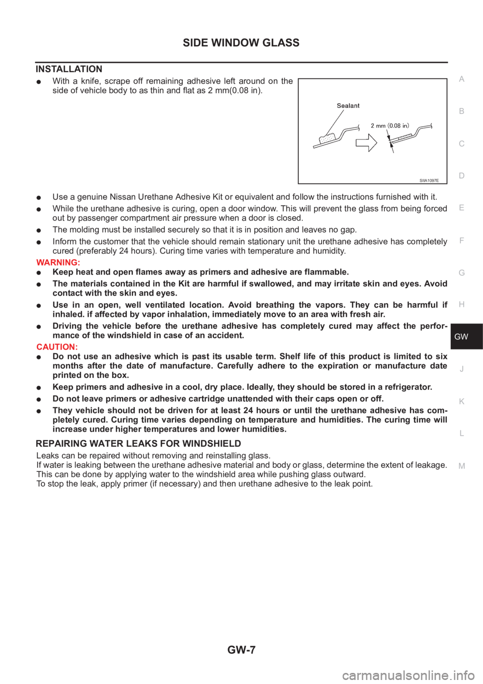
●With a knife, scrape off remaining adhesive left around on the
side of vehicle body to as thin and flat as 2 mm(0.08 in).
●Use a genuine Nissan Urethane Adhesive Kit or equivalent and follow the instructions furnished with it.
●While the urethane adhesive is curing, open a door window. This will prevent the glass from being forced
out by passenger compartment air pressure when a door is closed.
●The molding must be installed securely so that it is in position and leaves no gap.
●Inform the customer that the vehicle should remain stationary unit the urethane adhesive has completely
cured (preferably 24 hours). Curing time varies with temperature and humidity.
WARNING:
●Keep heat and open flames away as primers and adhesive are flammable.
●The materials contained in the Kit are harmful if swallowed, and may irritate skin and eyes. Avoid
contact with the skin and eyes.
●Use in an open, well ventilated location. Avoid breathing the vapors. They can be harmful if
inhaled. if affected by vapor inhalation, immediately move to an area with fresh air.
●Driving the vehicle before the urethane adhesive has completely cured may affect the perfor-
mance of the windshield in case of an accident.
CAUTION:
●Do not use an adhesive which is past its usable term. Shelf life of this product is limited to six
months after the date of manufacture. Carefully adhere to the expiration or manufacture date
printed on the box.
●Keep primers and adhesive in a cool, dry place. Ideally, they should be stored in a refrigerator.
●Do not leave primers or adhesive cartridge unattended with their caps open or off.
●They vehicle should not be driven for at least 24 hours or until the urethane adhesive has com-
pletely cured. Curing time varies depending on temperature and humidities. The curing time will
increase under higher temperatures and lower humidities.
REPAIRING WATER LEAKS FOR WINDSHIELD
Leaks can be repaired without removing and reinstalling glass.
If water is leaking between the urethane adhesive material and body or glass, determine the extent of leakage.
This can be done by applying water to the windshield area while pushing glass outward.
To stop the leak, apply primer (if necessary) and then urethane adhesive to the leak point.
SIIA1097E
Page 3160 of 3833
GW-8
BACK DOOR WINDOW GLASS
BACK DOOR WINDOW GLASS
PFP:90300
Removal and InstallationEIS0045K
REMOVAL
1. Remove rear wiper arm. Refer to WW-15, "Removal and Installation for Rear Wiper Arms" .
2. Remove rear washer nozzle. Refer to WW-17, "
Removal and Installation for Rear Washer Nozzle" .
3. Remove rear defogger connectors.
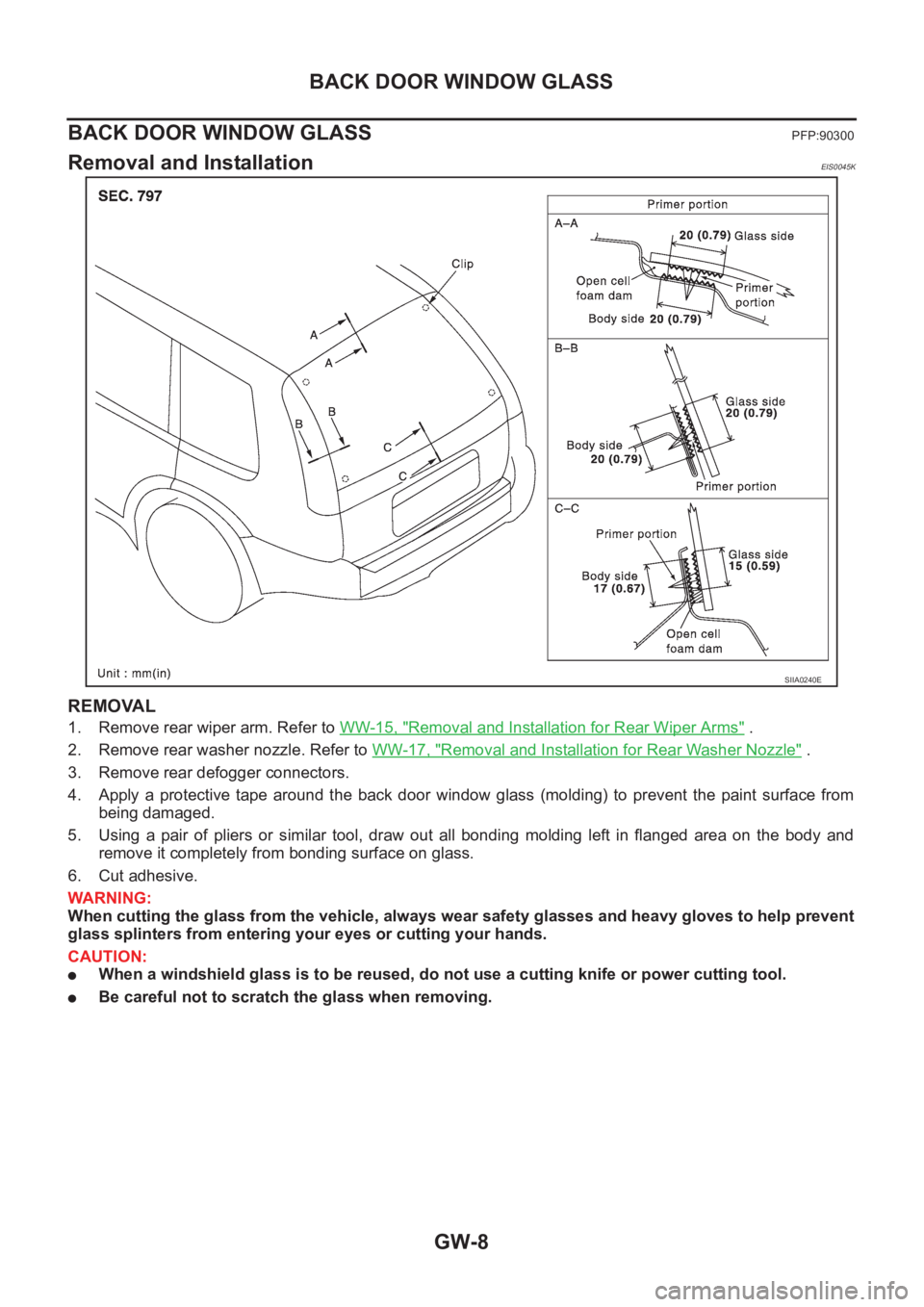
4. Apply a protective tape around the back door window glass (molding) to prevent the paint surface from
being damaged.
5. Using a pair of pliers or similar tool, draw out all bonding molding left in flanged area on the body and
remove it completely from bonding surface on glass.
6. Cut adhesive.
WARNING:
When cutting the glass from the vehicle, always wear safety glasses and heavy gloves to help prevent
glass splinters from entering your eyes or cutting your hands.
CAUTION:
●When a windshield glass is to be reused, do not use a cutting knife or power cutting tool.
●Be careful not to scratch the glass when removing.
SIIA0240E