NISSAN X-TRAIL 2001 Service Repair Manual
Manufacturer: NISSAN, Model Year: 2001, Model line: X-TRAIL, Model: NISSAN X-TRAIL 2001Pages: 3833, PDF Size: 39.49 MB
Page 3161 of 3833
BACK DOOR WINDOW GLASS
GW-9
C
D
E
F
G
H
J
K
L
MA
B
GW
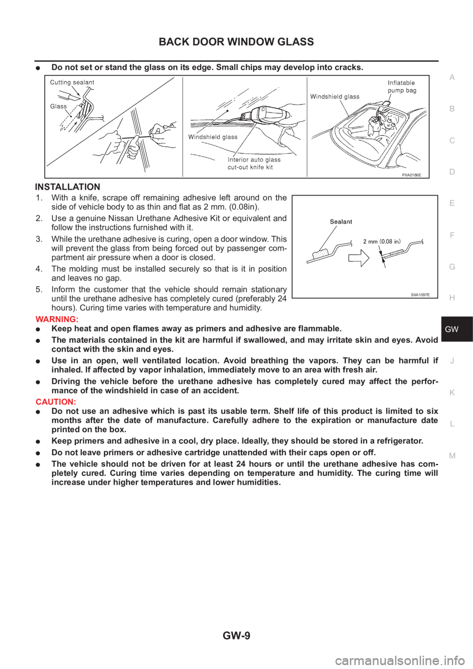
●Do not set or stand the glass on its edge. Small chips may develop into cracks.
INSTALLATION
1. With a knife, scrape off remaining adhesive left around on the
side of vehicle body to as thin and flat as 2 mm. (0.08in).
2. Use a genuine Nissan Urethane Adhesive Kit or equivalent and
follow the instructions furnished with it.
3. While the urethane adhesive is curing, open a door window. This
will prevent the glass from being forced out by passenger com-
partment air pressure when a door is closed.
4. The molding must be installed securely so that is it in position
and leaves no gap.
5. Inform the customer that the vehicle should remain stationary
until the urethane adhesive has completely cured (preferably 24
hours). Curing time varies with temperature and humidity.
WARNING:
●Keep heat and open flames away as primers and adhesive are flammable.
●The materials contained in the kit are harmful if swallowed, and may irritate skin and eyes. Avoid
contact with the skin and eyes.
●Use in an open, well ventilated location. Avoid breathing the vapors. They can be harmful if
inhaled. If affected by vapor inhalation, immediately move to an area with fresh air.
●Driving the vehicle before the urethane adhesive has completely cured may affect the perfor-
mance of the windshield in case of an accident.
CAUTION:
●Do not use an adhesive which is past its usable term. Shelf life of this product is limited to six
months after the date of manufacture. Carefully adhere to the expiration or manufacture date
printed on the box.
●Keep primers and adhesive in a cool, dry place. Ideally, they should be stored in a refrigerator.
●Do not leave primers or adhesive cartridge unattended with their caps open or off.
●The vehicle should not be driven for at least 24 hours or until the urethane adhesive has com-
pletely cured. Curing time varies depending on temperature and humidity. The curing time will
increase under higher temperatures and lower humidities.
PIIA0186E
SIIA1097E
Page 3162 of 3833
GW-10
REAR WINDOW DEFOGGER
REAR WINDOW DEFOGGER
PFP:25350
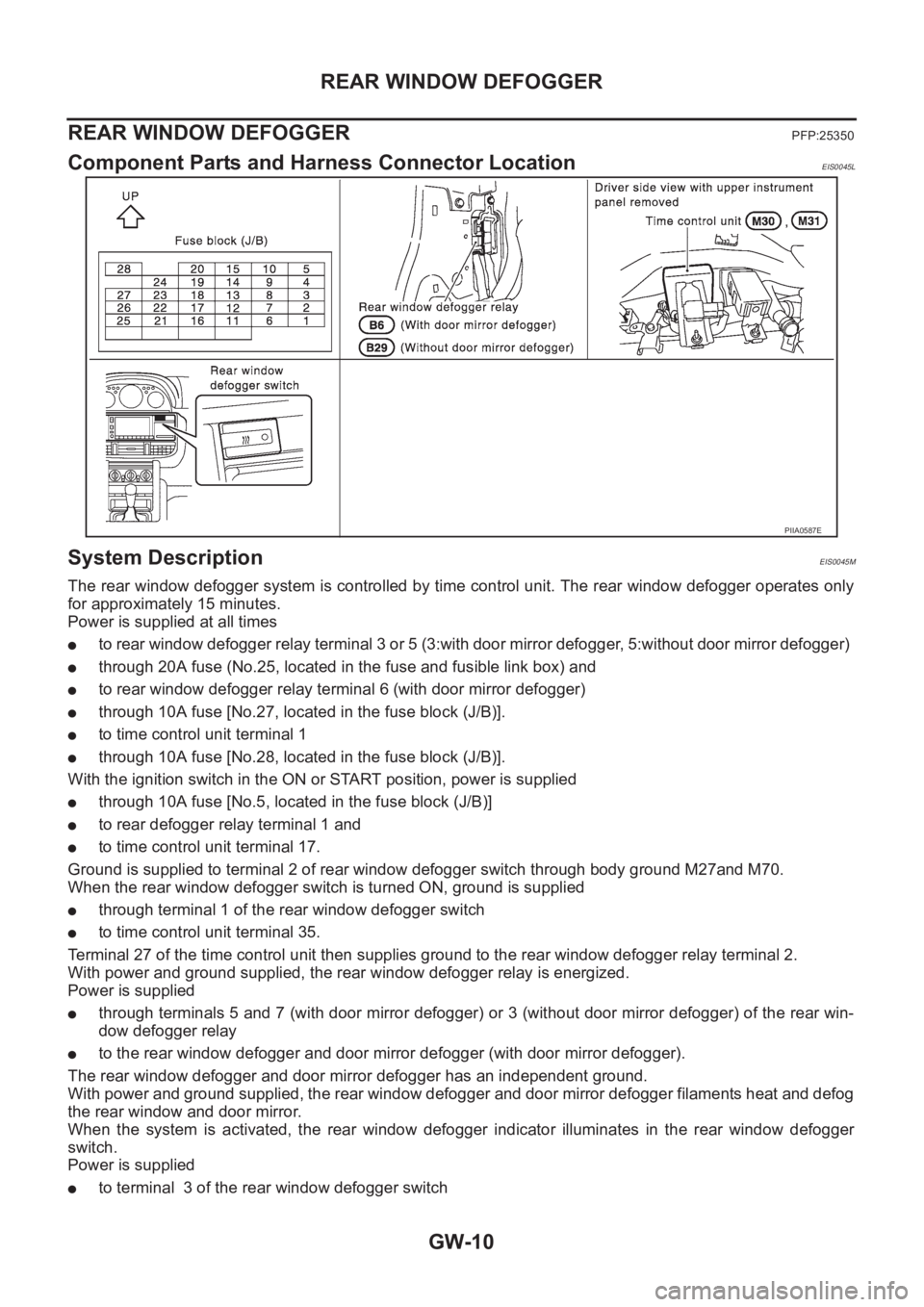
Component Parts and Harness Connector LocationEIS0045L
System DescriptionEIS0045M
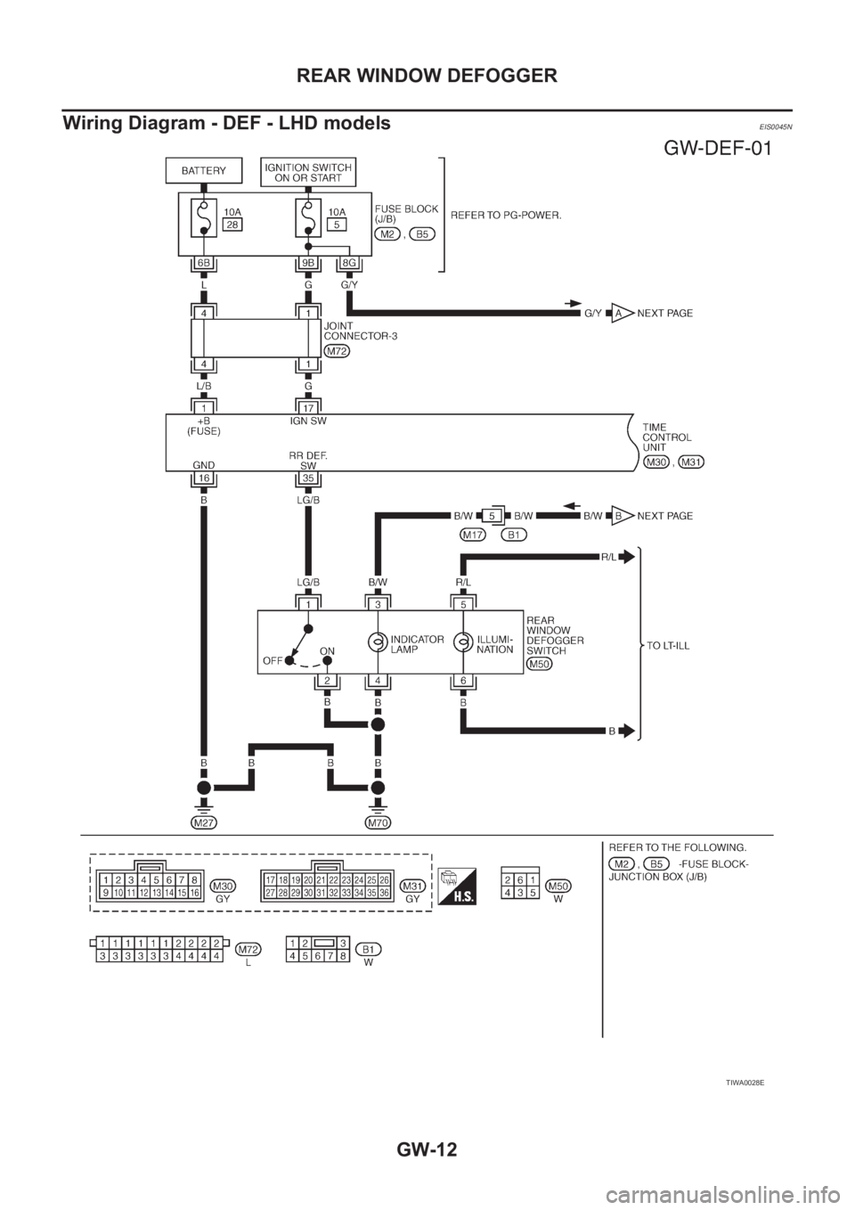
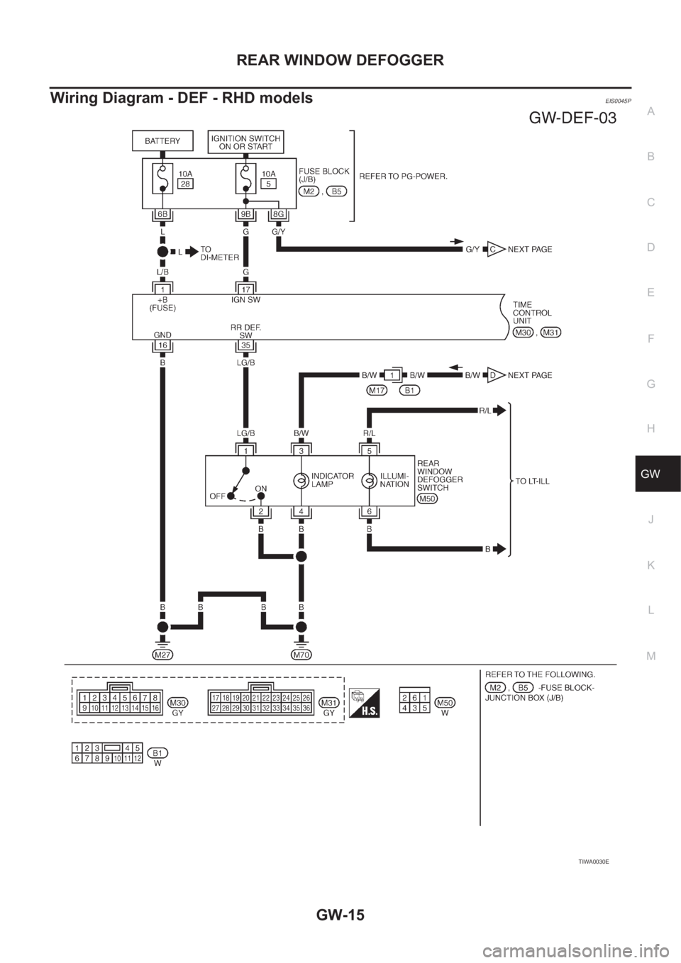
The rear window defogger system is controlled by time control unit. The rear window defogger operates only
for approximately 15 minutes.
Power is supplied at all times
●to rear window defogger relay terminal 3 or 5 (3:with door mirror defogger, 5:without door mirror defogger)
●through 20A fuse (No.25, located in the fuse and fusible link box) and
●to rear window defogger relay terminal 6 (with door mirror defogger)
●through 10A fuse [No.27, located in the fuse block (J/B)].
●to time control unit terminal 1
●through 10A fuse [No.28, located in the fuse block (J/B)].
With the ignition switch in the ON or START position, power is supplied
●through 10A fuse [No.5, located in the fuse block (J/B)]
●to rear defogger relay terminal 1 and
●to time control unit terminal 17.
Ground is supplied to terminal 2 of rear window defogger switch through body ground M27and M70.
When the rear window defogger switch is turned ON, ground is supplied
●through terminal 1 of the rear window defogger switch
●to time control unit terminal 35.
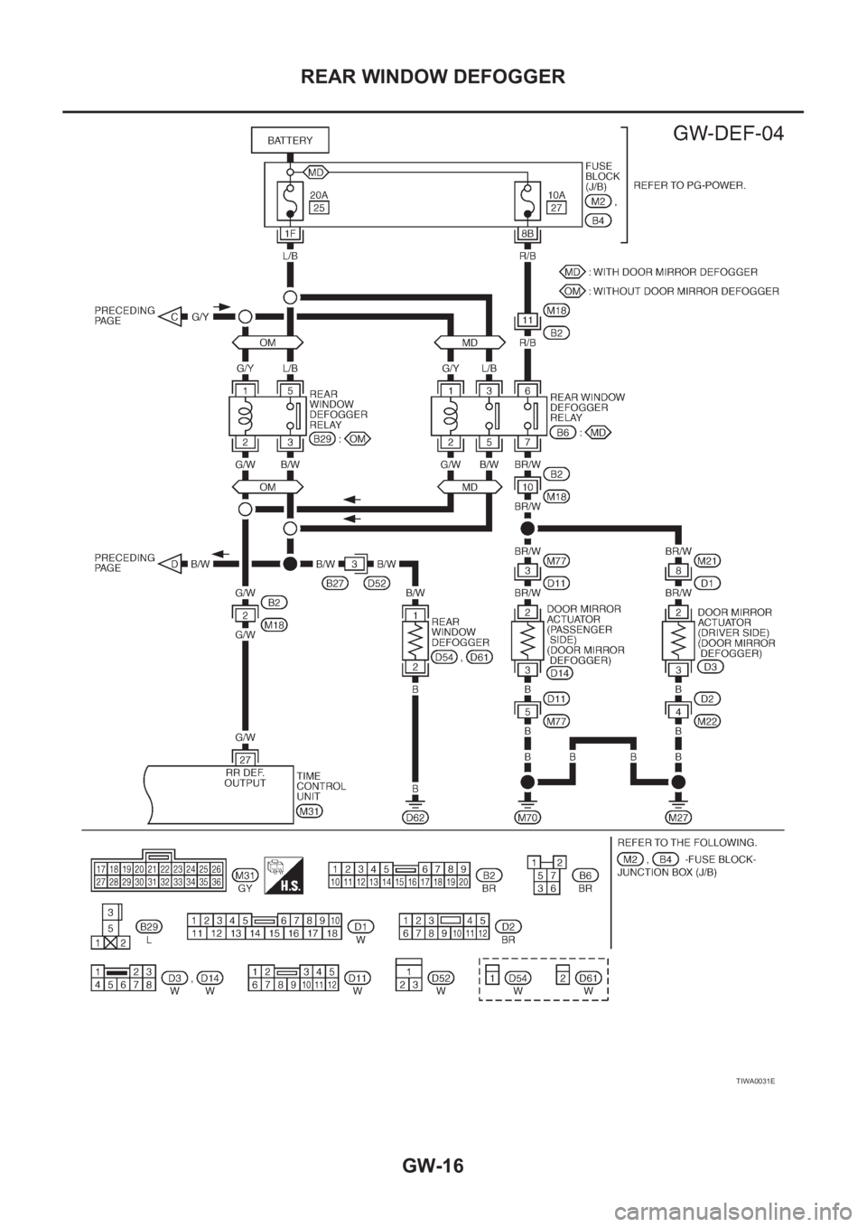
Terminal 27 of the time control unit then supplies ground to the rear window defogger relay terminal 2.
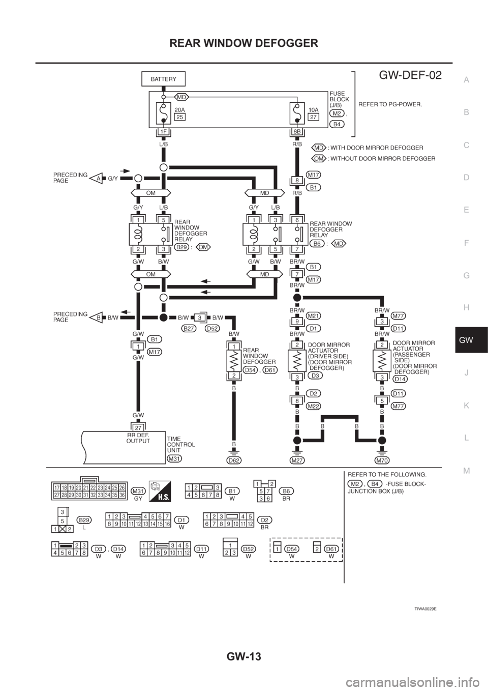
With power and ground supplied, the rear window defogger relay is energized.
Power is supplied
●through terminals 5 and 7 (with door mirror defogger) or 3 (without door mirror defogger) of the rear win-
dow defogger relay
●to the rear window defogger and door mirror defogger (with door mirror defogger).
The rear window defogger and door mirror defogger has an independent ground.
With power and ground supplied, the rear window defogger and door mirror defogger filaments heat and defog
the rear window and door mirror.
When the system is activated, the rear window defogger indicator illuminates in the rear window defogger
switch.
Power is supplied
●to terminal 3 of the rear window defogger switch
PIIA0587E
Page 3163 of 3833

REAR WINDOW DEFOGGER
GW-11
C
D
E
F
G
H
J
K
L
MA
B
GW
●from terminal 3 or 5 of rear window defogger relay.(3:with door mirror defogger, 5:without door mirror
defogger)
Terminal 4 of the rear window defogger switch is grounded through body ground M27 and M70.
Page 3164 of 3833
GW-12
REAR WINDOW DEFOGGER
Wiring Diagram - DEF - LHD models
EIS0045N
TIWA0028E
Page 3165 of 3833
REAR WINDOW DEFOGGER
GW-13
C
D
E
F
G
H
J
K
L
MA
B
GW
TIWA0029E
Page 3166 of 3833
GW-14
REAR WINDOW DEFOGGER
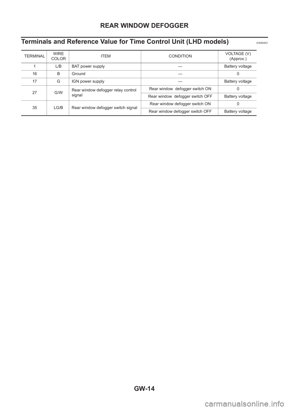
Terminals and Reference Value for Time Control Unit (LHD models)
EIS0045O
TERMINALWIRE
COLORITEM CONDITIONVOLTAGE (V)
(Approx.)
1 L/B BAT power supply — Battery voltage
16 B Ground — 0
17 G IGN power supply — Battery voltage
27 G/WRear window defogger relay control
signalRear window defogger switch ON 0
Rear window defogger switch OFF Battery voltage
35 LG/B Rear window defogger switch signalRear window defogger switch ON 0
Rear window defogger switch OFF Battery voltage
Page 3167 of 3833
REAR WINDOW DEFOGGER
GW-15
C
D
E
F
G
H
J
K
L
MA
B
GW
Wiring Diagram - DEF - RHD modelsEIS0045P
TIWA0030E
Page 3168 of 3833
GW-16
REAR WINDOW DEFOGGER
TIWA0031E
Page 3169 of 3833
REAR WINDOW DEFOGGER
GW-17
C
D
E
F
G
H
J
K
L
MA
B
GW
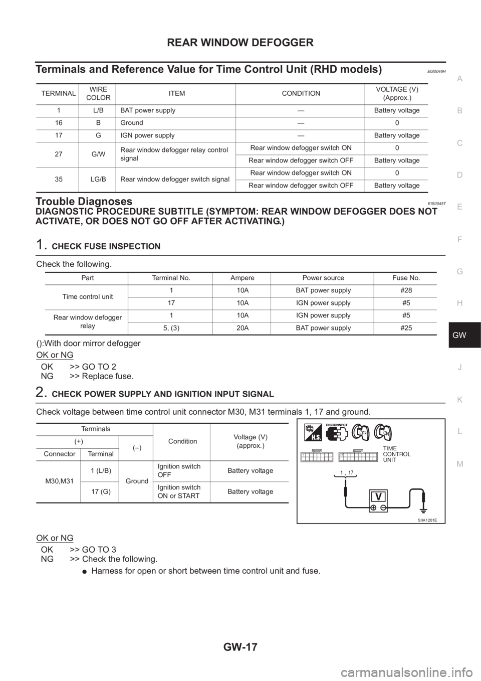
Terminals and Reference Value for Time Control Unit (RHD models)EIS0046H
Trouble DiagnosesEIS0045T
DIAGNOSTIC PROCEDURE SUBTITLE (SYMPTOM: REAR WINDOW DEFOGGER DOES NOT
ACTIVATE, OR DOES NOT GO OFF AFTER ACTIVATING.)
1.CHECK FUSE INSPECTION
Check the following.
():With door mirror defogger
OK or NG
OK >> GO TO 2
NG >> Replace fuse.
2.CHECK POWER SUPPLY AND IGNITION INPUT SIGNAL
Check voltage between time control unit connector M30, M31 terminals 1, 17 and ground.
OK or NG
OK >> GO TO 3
NG >> Check the following.
●Harness for open or short between time control unit and fuse.
TERMINALWIRE
COLORITEM CONDITIONVOLTAGE (V)
(Approx.)
1 L/B BAT power supply — Battery voltage
16 B Ground — 0
17 G IGN power supply — Battery voltage
27 G/WRear window defogger relay control
signalRear window defogger switch ON 0
Rear window defogger switch OFF Battery voltage
35 LG/B Rear window defogger switch signalRear window defogger switch ON 0
Rear window defogger switch OFF Battery voltage
Part Terminal No. Ampere Power source Fuse No.
Time control unit1 10A BAT power supply #28
17 10A IGN power supply #5
Rear window defogger
relay1 10A IGN power supply #5
5, (3) 20A BAT power supply #25
Terminals
ConditionVoltage (V)
(approx.) (+)
(–)
Connector Terminal
M30,M311 (L/B)
GroundIgnition switch
OFFBattery voltage
17 (G)Ignition switch
ON or STARTBattery voltage
SIIA1201E
Page 3170 of 3833
GW-18
REAR WINDOW DEFOGGER
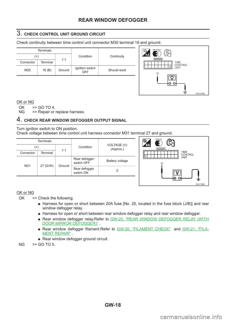
3. CHECK CONTROL UNIT GROUND CIRCUIT
Check continuity between time control unit connector M30 terminal 16 and ground.
OK or NG
OK >> GO TO 4.
NG >> Repair or replace harness.
4. CHECK REAR WINDOW DEFOGGER OUTPUT SIGNAL
Turn ignition switch to ON position.
Check voltage between time control unit harness connector M31 terminal 27 and ground.
OK or NG
OK >> Check the following.
●Harness for open or short between 20A fuse [No. 25, located in the fuse block (J/B)] and rear
window defogger relay.
●Harness for open or short between rear window defogger relay and rear window defogger.
●Rear window defogger relay.Refer to GW-20, "REAR WINDOW DEFOGGER RELAY (WITH
DOOR MIRROR DEFOGGER)" .
●Rear window defogger filament.Refer to GW-20, "FILAMENT CHECK" and GW-21, "FILA-
MENT REPAIR" .
●Rear window defogger ground circuit.
NG >> GO TO 5.
Te r m i n a l s
Condition Continuity (+)
(–)
Connector Terminal
M30 16 (B) GroundIgnition switch
OFFShould exist
SIIA1202E
Te r m i n a l s
ConditionVOLTAGE (V)
(Approx.) (+)
(–)
Connector Terminal
M31 27 (G/W) GroundRear defogger
switch OFFBattery voltage
Rear defogger
switch ON0
SIIA1198E