NISSAN X-TRAIL 2001 Service Repair Manual
Manufacturer: NISSAN, Model Year: 2001, Model line: X-TRAIL, Model: NISSAN X-TRAIL 2001Pages: 3833, PDF Size: 39.49 MB
Page 3201 of 3833
DOOR MIRROR
GW-49
C
D
E
F
G
H
J
K
L
MA
B
GW
DOOR MIRRORPFP:96301
Precautions to Handle Retractable Power Door MirrorsEIS004JO
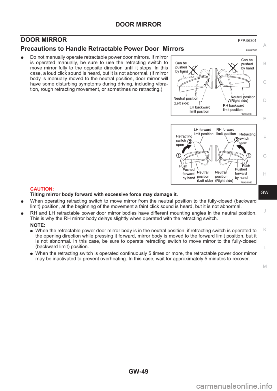
●Do not manually operate retractable power door mirrors. If mirror
is operated manually, be sure to use the retracting switch to
move mirror fully to the opposite direction until it stops. In this
case, a loud click sound is heard, but it is not abnormal. (If mirror
body is manually moved to the neutral position, door mirror will
have some disturbing symptoms during driving, including vibra-
tion, rough retracting movement, or sometimes no retracting.)
CAUTION:
Tilting mirror body forward with excessive force may damage it.
●When operating retracting switch to move mirror from the neutral position to the fully-closed (backward
limit) position, at the beginning of the movement a faint click sound is heard, but it is not abnormal.
●RH and LH retractable power door mirror bodies have different mounting angles in the neutral position.
This is why the RH mirror body delays slightly when operated with the retracting switch.
NOTE:
●When the retractable power door mirror body is in the neutral position, if retracting switch is operated to
the opening direction while pressing it forward, mirror body is moved to the forward limit position, but it
is not abnormal. In this case, be sure to operate retracting switch to move mirror to the fully-closed
(backward limit) position.
●When the retracting switch is operated continuously 5 times or more, the retractable power door mirror
may be inactivated to prevent overheating. In this case, wait for approximately 5 minutes to recover.
PIIA0513E
PIIA0514E
Page 3202 of 3833
GW-50
DOOR MIRROR
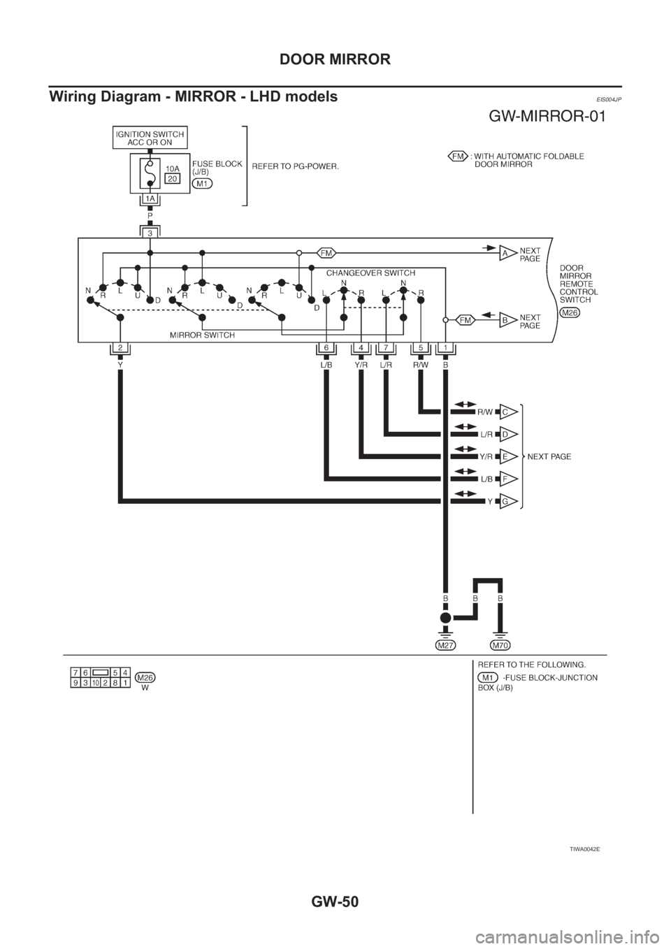
Wiring Diagram - MIRROR - LHD models
EIS004JP
TIWA0042E
Page 3203 of 3833
DOOR MIRROR
GW-51
C
D
E
F
G
H
J
K
L
MA
B
GW
TIWA0043E
Page 3204 of 3833
GW-52
DOOR MIRROR
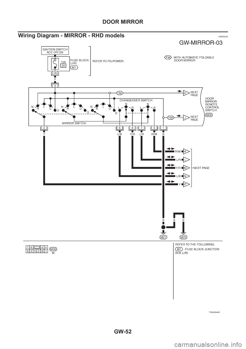
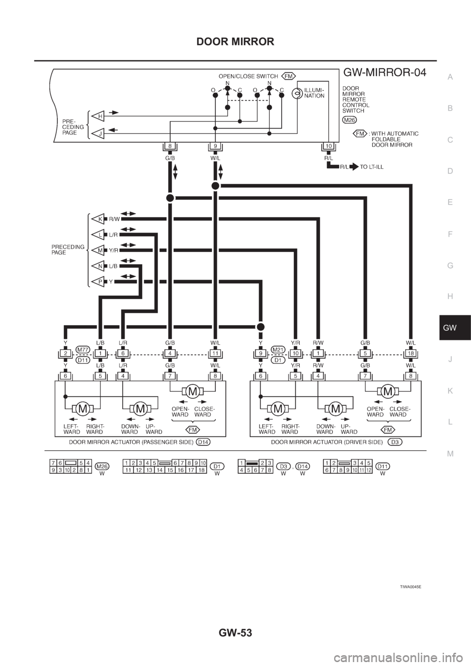
Wiring Diagram - MIRROR - RHD models
EIS004JQ
TIWA0044E
Page 3205 of 3833
DOOR MIRROR
GW-53
C
D
E
F
G
H
J
K
L
MA
B
GW
TIWA0045E
Page 3206 of 3833
GW-54
DOOR MIRROR
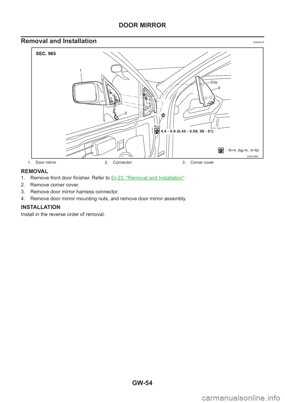
Removal and Installation
EIS004JR
REMOVAL
1. Remove front door finisher. Refer to EI-23, "Removal and Installation" .
2. Remove corner cover.
3. Remove door mirror harness connector.
4. Remove door mirror mounting nuts, and remove door mirror assembly.
INSTALLATION
Install in the reverse order of removal.
1. Door mirror 2. Connector 3. Corner cover
SIIA0186E
Page 3207 of 3833
DOOR MIRROR
GW-55
C
D
E
F
G
H
J
K
L
MA
B
GW
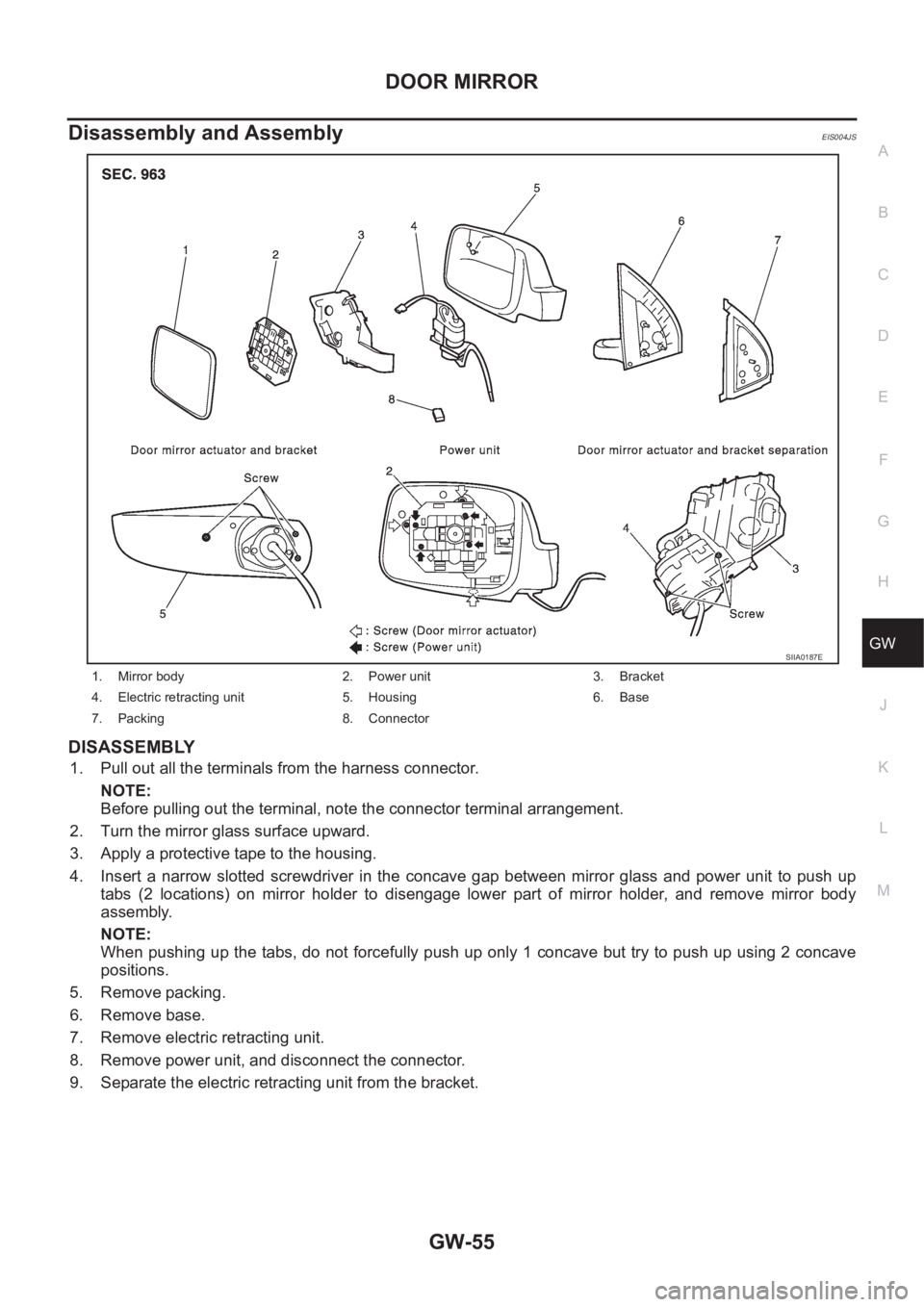
Disassembly and AssemblyEIS004JS
DISASSEMBLY
1. Pull out all the terminals from the harness connector.
NOTE:
Before pulling out the terminal, note the connector terminal arrangement.
2. Turn the mirror glass surface upward.
3. Apply a protective tape to the housing.
4. Insert a narrow slotted screwdriver in the concave gap between mirror glass and power unit to push up
tabs (2 locations) on mirror holder to disengage lower part of mirror holder, and remove mirror body
assembly.
NOTE:
When pushing up the tabs, do not forcefully push up only 1 concave but try to push up using 2 concave
positions.
5. Remove packing.
6. Remove base.
7. Remove electric retracting unit.
8. Remove power unit, and disconnect the connector.
9. Separate the electric retracting unit from the bracket.
1. Mirror body 2. Power unit 3. Bracket
4. Electric retracting unit 5. Housing 6. Base
7. Packing 8. Connector
SIIA0187E
Page 3208 of 3833
GW-56
DOOR MIRROR
ASSEMBLY
1. Install bracket to the electric retracting unit.
2. Connect power unit connector. Install electric retracting unit (bracket).
3. Install electric retracting unit and base to the housing.
4. Place power unit and mirror body assembly in a horizontal position.
5. Engage upper tabs of mirror glass with power unit. Then, press lower part of mirror glass down until the
lower part snaps to allow engagement of lower tabs.
NOTE:
After installation, visually check that the lower tabs (2) are securely engaged when viewed from the bot-
tom of mirror surface.
6. Install the packing to the base.
7. Insert the harness terminal into the connector.
NOTE:
Make sure to insert the harness terminal into the correct connector. Do not confuse the locations.
Page 3209 of 3833
RF-1
ROOF
I BODY
CONTENTS
C
D
E
F
G
H
J
K
L
M
SECTION
A
B
RF
ROOF
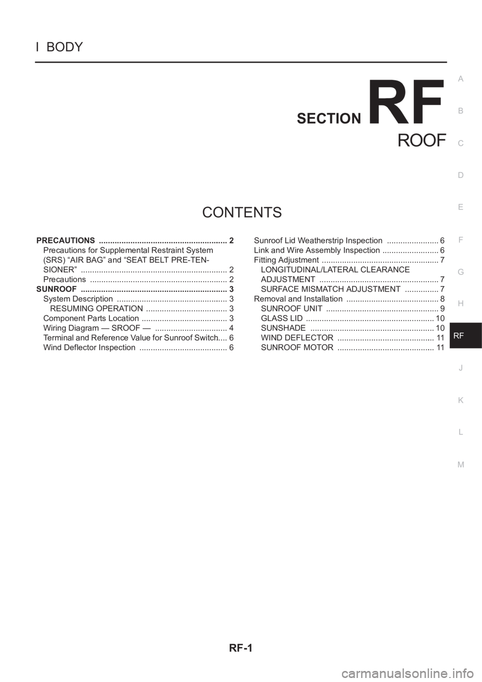
PRECAUTIONS .......................................................... 2
Precautions for Supplemental Restraint System
(SRS) “AIR BAG” and “SEAT BELT PRE-TEN-
SIONER” .................................................................. 2
Precautions .............................................................. 2
SUNROOF .................................................................. 3
System Description .................................................. 3
RESUMING OPERATION ..................................... 3
Component Parts Location ....................................... 3
Wiring Diagram — SROOF — ................................. 4
Terminal and Reference Value for Sunroof Switch ..... 6
Wind Deflector Inspection ........................................ 6Sunroof Lid Weatherstrip Inspection ........................ 6
Link and Wire Assembly Inspection .......................... 6
Fitting Adjustment ..................................................... 7
LONGITUDINAL/LATERAL CLEARANCE
ADJUSTMENT ...................................................... 7
SURFACE MISMATCH ADJUSTMENT ................ 7
Removal and Installation .......................................... 8
SUNROOF UNIT ................................................... 9
GLASS LID .......................................................... 10
SUNSHADE ........................................................ 10
WIND DEFLECTOR ............................................ 11
SUNROOF MOTOR ............................................ 11
Page 3210 of 3833
RF-2
PRECAUTIONS
PRECAUTIONS
PFP:00001
Precautions for Supplemental Restraint System (SRS) “AIR BAG” and “SEAT
BELT PRE-TENSIONER”
EIS0044P
The Supplemental Restraint System such as “AIR BAG” and “SEAT BELT PRE-TENSIONER”, used along
with a front seat belt, helps to reduce the risk or severity of injury to the driver and front passenger for certain
types of collision. Information necessary to service the system safely is included in the SRS and SB section of
this Service Manual.
WARNING:
●To avoid rendering the SRS inoperative, which could increase the risk of personal injury or death
in the event of a collision which would result in air bag inflation, all maintenance must be per-
formed by an authorized NISSAN/INFINITI dealer.
●Improper maintenance, including incorrect removal and installation of the SRS, can lead to per-
sonal injury caused by unintentional activation of the system. For removal of Spiral Cable and Air
Bag Module, see the SRS section.
●Do not use electrical test equipment on any circuit related to the SRS unless instructed to in this
Service Manual. SRS wiring harnesses can be identified by yellow and/or orange harness connec-
tors.
Precautions EIS0044Q
●When removing or disassembling any part, be careful not to damage or deform it. Protect parts, which
may get in the way with cloth.
●When removing parts with a screwdriver or other tool, protect parts by wrapping them with vinyl or tape.
●Keep removed parts protected with cloth.
●If a clip is deformed or damaged, replace it.
●If an unreusable part is removed, replace it with a new one.
●Tighten bolts and nuts firmly to the specified torque.
●After re-assembly has been completed, make sure each part functions correctly.
●Remove stains in the following way.
Water-soluble stains:
Dip a soft cloth in warm water, and then squeeze it tightly. After wiping the stain, wipe with a soft dry cloth.
Oil stain:
Dissolve a synthetic detergent in warm water (density of 2 to 3% or less), dip the cloth, then clean off the stain
with the cloth. Next, dip the cloth in fresh water and squeeze it tightly. Then clean off the detergent completely.
Then wipe the area with a soft dry cloth.
●Do not use any organic solvent, such as thinner or benzine.
●If sunroof motor operation sound is noted but sunroof does not operate, replace motor assembly with
glass lid fully closed.
●If sunroof (glass lid and motor) does not operate when using sunroof switch then remove the front cover of
the luggage compartment, and rotate motor gear box drive shaft with the emergency handle (in the tool
box).